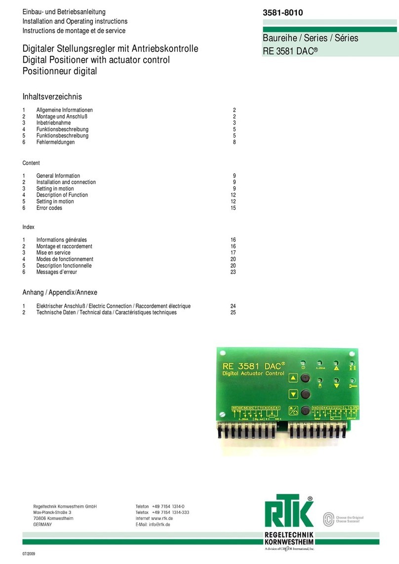
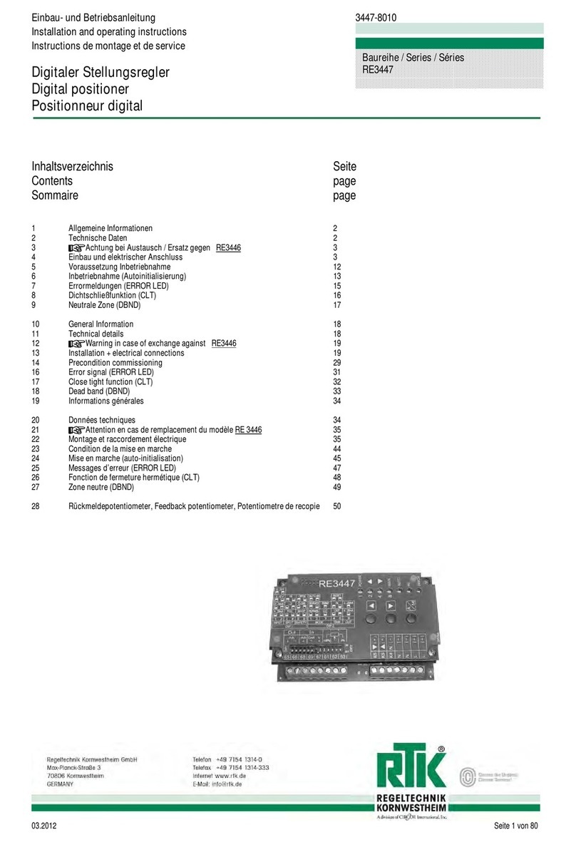
RTK REpos-8010 User manual

Digitaler Stellungsregler
Digital positioner
Positionneur digital
REpos-8010
19.10.2017 REpos-8010.docx Technische Änderungen vorbehalten / Technical changes reserved / Modifications techniques sous réserve page 33
20. General Information......................................................................................................................................................................35
20.1 Warning!.......................................................................................................................................................................................................35
21. Technical details...........................................................................................................................................................................35
21.1 Electromagnetic compatibility (EMC)...........................................................................................................................................................35
21.2 Electrical details...........................................................................................................................................................................................35
22. Feedback potentiometer installation and adjustment...............................................................................................................36
22.1 Pre-conditions required for adjustment of the feedback potentiometer .......................................................................................................36
22.2 Required parts .............................................................................................................................................................................................37
23. Installation REpos.........................................................................................................................................................................39
23.1 Required parts .............................................................................................................................................................................................39
24. Wiring diagram REact 15E ...........................................................................................................................................................43
25. Wiring diagram REact 30/ 60/ 100................................................................................................................................................44
26. Wiring diagram REact 60E-170 / …100E-090..............................................................................................................................45
27. Wiring diagram REact 30-DC/ 60-DC/ 100-DC ............................................................................................................................46
28. Wiring diagram REact 30-DC/ 60-DC/ 100-DC with int. power supply......................................................................................47
29. Electrical connections..................................................................................................................................................................48

Digitaler Stellungsregler
Digital positioner
Positionneur digital
REpos-8010
19.10.2017 REpos-8010.docx Technische Änderungen vorbehalten / Technical changes reserved / Modifications techniques sous réserve page 34
30. Operation.......................................................................................................................................................................................49
30.1 Operation .....................................................................................................................................................................................................50
30.2 Automatic mode operation...........................................................................................................................................................................50
30.3 Manual mode operation ...............................................................................................................................................................................50
30.4 Menu navigation...........................................................................................................................................................................................50
30.5 Editing parameter.........................................................................................................................................................................................50
31. General menu map........................................................................................................................................................................51
31.1 Diagnostic menu map ..................................................................................................................................................................................52
31.2 Diagnostic data ............................................................................................................................................................................................53
31.3 Configuration menu map..............................................................................................................................................................................54
31.4 Configuration parameter ..............................................................................................................................................................................55
31.5 General operation commands menu map ...................................................................................................................................................56
32. Commands ....................................................................................................................................................................................57
32.1 Auto Initialization Procedure ........................................................................................................................................................................57
32.2 Auto initialization procedure menu map.......................................................................................................................................................58
32.3 Input calibration procedure menu map ........................................................................................................................................................59
33. Setpoint vs Effective Actuator Direction (SpRv)........................................................................................................................60
34. Split Range Mode (SplM)..............................................................................................................................................................61
35. Setpoint vs Valve Stroke Characteristic (SpLn).........................................................................................................................62
36. Close Tight Function (ClTe).........................................................................................................................................................63
37. Minimum Travel Time Out (MnTT) ...............................................................................................................................................64

Digitaler Stellungsregler
Digital positioner
Positionneur digital
REpos-8010
19.10.2017 REpos-8010.docx Technische Änderungen vorbehalten / Technical changes reserved / Modifications techniques sous réserve page 35
20. General Information
20.1 Warning!
Before beginning the installation or operation of electrical equipment, please read the following print
"Warnings of hazards..."
”All work on electrical systems or production equipment must be carried out by authorized personnel.
Electrical installation (cables) must be carried out according to the regulations applicable in the
respective countries (Germany VDE 100).
Measurement and signal cable must be kept separate from power cables to avoid EMC effects.
If a riskless operation is no longer possible, the equipment must be taken out of service and made safe
against accidental operation.
lThe electronics in the positioner contains components that are susceptible to electric static.
Electric static discharges must be avoided using suitable measures.
21. Technical details
21.1 Electromagnetic compatibility (EMC)
Regarding EMCthe positioner complies with the following regulations and directives:
Directive 2014/35/EU and EN61010-1:2011-07 for electrical equipment
Directive 2004/108/EEC for electromagnetic compatibility.
Regulations for HF Emission: EN61000-6-4:2007 for industrial environment
Regulations for HF Immunity to interference: EN61000-6-2:2005 for industrial equipment
21.2 Electrical details
data electrical
Display
128*64 dot graphic display
Input
current 0(4)-20mA/ Rica. 10[/voltage 0(2)-10V Rica. 100k[
control output AC version
solid state relays (SSR) max 250V / 50/60Hz 2.5A
control output DC version
high side transistor 24 V dc 100mA max
feedback potentiometer
conductive plastic 1k[or angle sensor (Uv5V)
feedback signal optional
current 0(4)-20mA/ RLca. 500[/voltage 0(2)-10V galvanic isolated
supply
115/230V 50/60Hz or 24V 50/60Hz or 24V dc
power consumption
ca. 3VA
data mechanical
electrical connection
plug connector supply AWG 24-12 / signal AWG 26-16
screw supply plug
M3 / 0.34Nm
screw signal plug
M2 / 0.34Nm

Digitaler Stellungsregler
Digital positioner
Positionneur digital
REpos-8010
19.10.2017 REpos-8010.docx Technische Änderungen vorbehalten / Technical changes reserved / Modifications techniques sous réserve page 36
22. Feedback potentiometer installation and adjustment
22.1 Pre-conditions required for adjustment of the feedback potentiometer
The actuator must be mounted and adjusted on the control valve
Fasten the actuator to the valve body using the
pillars.(2)
Connect the valve plug / spindle with the actuator
spindle (1)
Set the limit switches to the real stroke of the
control valve. i.e. It must be certain that the
actuator switches off when the end position has
been reached.(3)
pls note cut off modes!!
( limit or torque switch off)
Pictures are exemplary und apply for all actuators Type REact
1
2
3

Digitaler Stellungsregler
Digital positioner
Positionneur digital
REpos-8010
19.10.2017 REpos-8010.docx Technische Änderungen vorbehalten / Technical changes reserved / Modifications techniques sous réserve page 37
22.2 Required parts
Actuator Type REact
1 x potentiometer-group
1 x potentiometer-pinions
1 x leg spring
1 x screw M3x 12 TX10
1 x nut M3 SW 5.5
2 x washer
1 x distance bush
Select potentiometer pinion depending on
the real valve stroke.
Up to 50mm real valve stroke...
Nr.1 stroke 0-24mm (dk 10.5mm)
Nr.2 stroke 25-29mm (dk 12.6mm)
Nr.3 stroke 30-36mm (dk 16.1mm)
Nr.4 stroke 37-54mm (dk 23.1mm)
From > 50mm real valve stroke
(Actuator with adaption spindle)
Nr.4 stroke 37-54mm (dk 23.1mm)
Push the selected pinion on the
potentiometer shaft.
1
2
4
3

Digitaler Stellungsregler
Digital positioner
Positionneur digital
REpos-8010
19.10.2017 REpos-8010.docx Technische Änderungen vorbehalten / Technical changes reserved / Modifications techniques sous réserve page 38
Actuator Type REact
Drive the actuator in 0% stroke position as shown.
Actuator must be switch off in
0% position via limit / torque switch.
Install the leg spring as shown
Install the potentiometer group as shown
The leg spring must keep the
potentiometer pinion form closed with
the teeth of the slide!
Rotate adjusting ring until the marking (A)and(B)
are aligned as shown.
Fasten the pinion securely in place (C) by using an
Allen key (size 1.5).
A
B
C

Digitaler Stellungsregler
Digital positioner
Positionneur digital
REpos-8010
19.10.2017 REpos-8010.docx Technische Änderungen vorbehalten / Technical changes reserved / Modifications techniques sous réserve page 39
Actuator Type REact
Check the resistance in 0% position.
The measured value between the grey and red
wire should be approx. 100[±20[
23. Installation REpos
23.1 Required parts
1x mounting bracket
4x screw M4 x10 (TX20)
1x power-board
4x distance bolt (5,5x20mm) self-cutting
1x CPU-board (Display)
4x screw M3 x6 (Philips screw)
optional
signal feedback -module
4x screw 3x6 self-cutting (TX10)

Digitaler Stellungsregler
Digital positioner
Positionneur digital
REpos-8010
19.10.2017 REpos-8010.docx Technische Änderungen vorbehalten / Technical changes reserved / Modifications techniques sous réserve page 40
Fasten mounting bracket as shown.
4x screw M4 x 10 (TX20)
Fix the Power-board
4x distance bolt (5,5x20mm) self-cutting
optional
Connect feedback module with CPU-board as
shown.

Digitaler Stellungsregler
Digital positioner
Positionneur digital
REpos-8010
19.10.2017 REpos-8010.docx Technische Änderungen vorbehalten / Technical changes reserved / Modifications techniques sous réserve page 41
Connect CPU-board with power board
”
Pay attention that plug in connector is connected
correctly.
Plug and socket connection OK
Plug and socket connection not OK
Fasten the CPU-board
4x screw M3 x6 (Philips screw)

Digitaler Stellungsregler
Digital positioner
Positionneur digital
REpos-8010
19.10.2017 REpos-8010.docx Technische Änderungen vorbehalten / Technical changes reserved / Modifications techniques sous réserve page 42
optional
Fix feedback module
4x screw 3x6 self-cutting(TX10)
Connect pre adjusted feedback potentiometer.
Yellow wireterminal 61
Grey wire terminal 62
Red wire terminal 63
Connect positioner output with actuator.
Grey wire terminal K4 to terminal A1
Red wire terminal K5 to terminal A2
Yellow wire terminal K6 to terminal A3

Digitaler Stellungsregler
Digital positioner
Positionneur digital
REpos-8010
19.10.2017 REpos-8010.docx Technische Änderungen vorbehalten / Technical changes reserved / Modifications techniques sous réserve page 43
24. Wiring diagram REact 15E

Digitaler Stellungsregler
Digital positioner
Positionneur digital
REpos-8010
19.10.2017 REpos-8010.docx Technische Änderungen vorbehalten / Technical changes reserved / Modifications techniques sous réserve page 44
25. Wiring diagram REact 30/ 60/ 100

Digitaler Stellungsregler
Digital positioner
Positionneur digital
REpos-8010
19.10.2017 REpos-8010.docx Technische Änderungen vorbehalten / Technical changes reserved / Modifications techniques sous réserve page 45
26. Wiring diagram REact 60E-170 / …100E-090

Digitaler Stellungsregler
Digital positioner
Positionneur digital
REpos-8010
19.10.2017 REpos-8010.docx Technische Änderungen vorbehalten / Technical changes reserved / Modifications techniques sous réserve page 46
27. Wiring diagram REact 30-DC/ 60-DC/ 100-DC

Digitaler Stellungsregler
Digital positioner
Positionneur digital
REpos-8010
19.10.2017 REpos-8010.docx Technische Änderungen vorbehalten / Technical changes reserved / Modifications techniques sous réserve page 47
28. Wiring diagram REact 30-DC/ 60-DC/ 100-DC with int. power supply

Digitaler Stellungsregler
Digital positioner
Positionneur digital
REpos-8010
19.10.2017 REpos-8010.docx Technische Änderungen vorbehalten / Technical changes reserved / Modifications techniques sous réserve page 48
29. Electrical connections

Digitaler Stellungsregler
Digital positioner
Positionneur digital
REpos-8010
19.10.2017 REpos-8010.docx Technische Änderungen vorbehalten / Technical changes reserved / Modifications techniques sous réserve page 49
30. Operation
Display 1 indicates the current position (0-100%) in manual / automatic operation
and the parameter name at configuration level.
Display 2 indicates the in manual / automatic operation the target position (0-100%)
and the parameter value at configuration level.
Decrement Key D serves to navigate through the parameter menu
and to decrease the selected parameter values.
or to move the actuator in manual mode
Increment Key Iserves to navigate through the parameter menu
and to increase the selected parameter values
or to move the actuator in manual mode
Interface(micro USB) for RTK internal use only!
aImproper use can lead to the destruction of the device!

Digitaler Stellungsregler
Digital positioner
Positionneur digital
REpos-8010
19.10.2017 REpos-8010.docx Technische Änderungen vorbehalten / Technical changes reserved / Modifications techniques sous réserve page 50
30.1 Operation
The REpos is operated by the three key switches.
The A/M Key serves to switch over the operating modes
and select the menu items.
The decrement key Dserves to navigate through the parameter menu,
and to decrease the selected parameter value.
The increment key Iserves to navigate through the parameter menu
and to increase the selected parameter value.
30.2 Automatic mode operation
Key function:
Key
Description
A/M
single press (1s)
switch to manual mode
long press (>4s)
switch to diagnostic/configuration/command mode
D
press
no effect
I
press
no effect
30.3 Manual mode operation
Key function
Key
Action
Description
A/M
single press (1s)
switch to automatic mode
long press (>4s)
switch to diagnostic/configuration/command mode
D
press
close output actuated
I
press
open output actuated
30.4 Menu navigation
Key function
Key
Action
Description
A/M
press (1s)
menu item selection
long press (>4s)
exit menu
D
press
next menu item
I
press
previous menu item
30.5 Editing parameter
Key function
Key
Action
Description
A/M
press (1s)
confirm the value and proceed to next item
long press (>4s)
exit the menu and discard value change
D
press
decrease value / go to next parameter
I
press
increase value / go to previous parameter

Digitaler Stellungsregler
Digital positioner
Positionneur digital
REpos-8010
19.10.2017 REpos-8010.docx Technische Änderungen vorbehalten / Technical changes reserved / Modifications techniques sous réserve page 51
31. General menu map
enter password

Digitaler Stellungsregler
Digital positioner
Positionneur digital
REpos-8010
19.10.2017 REpos-8010.docx Technische Änderungen vorbehalten / Technical changes reserved / Modifications techniques sous réserve page 52
31.1 Diagnostic menu map
Table of contents
Other RTK Valve Positioner manuals
Popular Valve Positioner manuals by other brands

YASKAWA
YASKAWA MH SIGMA-5 Series manual

Omron
Omron H8PS instruction manual

Omron
Omron 3F88L-160 Connection manual

Atlas Copco
Atlas Copco ILS Target Quad STB-S Product instructions

Baker Hughes
Baker Hughes Masoneilan 47 P Series instruction manual

Westlock
Westlock 2200 Installation and operating instructions