M2 Antenna Systems FGAE1000-D1-W-COS-A-H User manual

M2 Antenna Systems, Inc. 4402 N. Selland Ave. Fresno, CA 93722
Tel: (559) 432-8873 Fax: (559) 432-3059 Web: www.m2inc.com
©2018 M2 Antenna Systems Incorporated 12/20/21
REV A
M2 Antenna Systems, Inc.
Model No: FGAE1000-D1-W-COS-A-H
SPECIFICATIONS:
Model ........................................ FGAE1000-D1-W-C-A-H
Motor Type ................................ DC Motor
Worm Gear Configuration ......... Single
Enclosure Type ......................... Weatherproof
Mount Style................................ Cross Boom
Body Material............................. Aluminum
Environment Control.................. Heater

SYSTEM OVERVIEW & DIMENSIONS
BEFORE YOU BEGIN: Look over all the DRAWINGS to get familiar with the various parts and assem-
blies in the system. Tools handy for assembly process: screwdriver, 11/32, 7/16, 1/2, 9/16 and 5/8” spin
-tites, end wrenches and/or sockets, measuring tape.
Note:
All installations are unique in some way, which means it's OK to preassemble certain hardware, or
rearrange the assembly process to meet specific site requirements. A quick review of the assembly
notes and drawings should help firm up the appropriate strategy. Please remember to double-check
all hardware for tightness BEFORE it becomes inaccessible.
Two containers of zinc paste (Penetrox, Noalox, or equiv.) have been provided to enhance
and maintain the quality of all electrical junctions on this system. Apply a thin coat wherever
two pieces of aluminum come in contact or any other electrical connections are made. It is
also useful on screws and bolt threads as an ANTI SEIZE compound.

3” PIPE CLAMPS (OPTIONAL)
6” PIPE CLAMPS (OPTIONAL)
6” PIPE
(CUSTOMER SUPPLIED)
PIPE CLAMP #1
(QTY. 3)
PIPE CLAMP #2
(QTY. 3)
BOLT,3/8-16 X 4.0 HEX,SS
(QTY. 6)
LOCKWASHER,3/8”,SS
(QTY. 6)
BOLT,5/16-18 X 2.0, HEX HD,SS
(QTY. 2)
FLATWASHER,5/16,SS
(QTY. 2)
LOCKNUT,5/16-18,SS
(QTY. 2)
PIPE STOP
AZ-1000
ASSEMBLY
BOLT,3/816 X 1.0
SCKT HD,SS
(QTY. 6)
3” PIPE
(CUSTOMER SUPPLIED)
PIPE CLAMP #1
(QTY. 3)
PIPE CLAMP #2
(QTY. 3)
BOLT,5/16-18 X 2”,SS
FLATWASHER,5/16”,SS
PIPE STOPBOLT,3/8-16 X 3”,SS
LOCKWASHER,3/8”,SS
BOLT,3/816 X 1.0
SCKT HD,SS
(QTY. 6)
AZ-1000
ASSEMBLY

FGAE1000-D1-W-COS-A-H ASSEMBLY
BOLT, 3/8-16 x 1”
SS
(QTY 5)
AZ-1000W
BOLT, 3/8-16 x 1”
SS
(QTY 5)
BOLT, 3/8-16 x 3/4”
SS
(QTY 1)
CROSS BOOM PLUG IN
USE: BOLT, 1/4-20 X 3”, SS
LOCKNUT, 1/4-20, SS
(BOTH SIDES)
AZ-1000W
EL-1000W

CABLE BRIDGE
ARM
FGAE1000-D1-W-C0S-A-H ASSEMBLY
CABLE BRIDGE
BOLT, 1/4-20 X 1.0 SS
LOCKNUT, 1/4-20 SS
2.4 CRADLE
BOLT, 1/4-20 X 3.5 SS
LOCKNUT, 1/4-20 SS
ON CENTER CABLE
PASS THROUGH

FGAE1000-D1-W-COS-A-H ASSEMBLY
≈ 10-30
DEG
NOTE: When using 180 degrees over the top elevation movement during tracking, the cable bridge
can collide with the cable routing bar and associated cables. When mounting the cable bridge, be sure
the elevation system is on the horizon, then position the cable bridge 10-30 degrees below the horizon
to avoid collision with the cable routing bar. Confirm clearance before any un-manned operations.
CABLE BRIDGE

CABLE ROUTING
The new AE1000-D1-W-COS-A-N helps to simplify the cable routing process by allowing the cable to pass through the
Azimuth axis. This simple change can save on costly repairs when cable get snagged keeping the system from performing.
LARGE NYLON TIES
TO HOLD DOWN
POWER DIVIDERS
AND OR FEED LINES
CABLE BRACE

CABLE ROUTING
Note: When cable routing, each axis should be positioned at the centers of each travel spectrum. Az: If your AZ
is set for south center, then position the AZ at 180 deg. EL: if your EL is set for 0 to 90 deg. The set your EL for
45 deg. This way the cables will only need to flex for 1/2 of the total movement on each direction of rotation.
Elevation Loop
The Elevation axis control cable comes up through the AZ assembly cable pass through and attaches to the
elevation motor unit. Note the RF cables from the antennas come from either side of the H-Frame and onto the
cable bridge then they should loop around the Elevation axis body then down through the cable pass through.
The loop around the Elevation body will provide a loop that will expand and contract as the elevation moves up
or down in rotation. Temporarily use electrical tape or nylon ties to hold the cables together and to the cable
brace. Drive the Elevation axis to both ends of the travel and watch the cables to be sure they do not become to
tight or get hung up. Make adjustments as needed, this may take multiple passes to feel comfortable with the
cable rap and cable loop. Once you feel comfortable with the cable rap and its movement add nylon ties to the
cable brace. Note: multiple slots have been added to the cable brace to give adequate positions for small and
large cable bundles. Taping or the use of nylon tie to keep the bundle together below the cable pass through is
recommended
NOTE:
GENERIC POWER DIVIDER
BRIDGE SHOWN FOR
CABLE ROUTE EXAMPLE.
POWER DIVIDER BRIDGE
SETUP MAY BE DIFFERENT.
REFER TO MASTER SYSTEM
MANUAL FOR MORE DETAILS.
LARGE NYLON TIES
TO HOLD DOWN
POWER DIVIDERS
AND OR FEED LINES

CABLE ROUTE FLAG & BRIDGE
AZ Cable Route
The Azimuth axis control cable simply attaches to the AZ axis then loops down and back to the full cable bundle
coming from the bottom of the cable pass through 6 to 12 inches below the exit of the pass through. Taping or
the use of nylon tie to keep the lower main cable bundle together below the cable pass through is recommend-
ed.

DESCRIPTION QTY
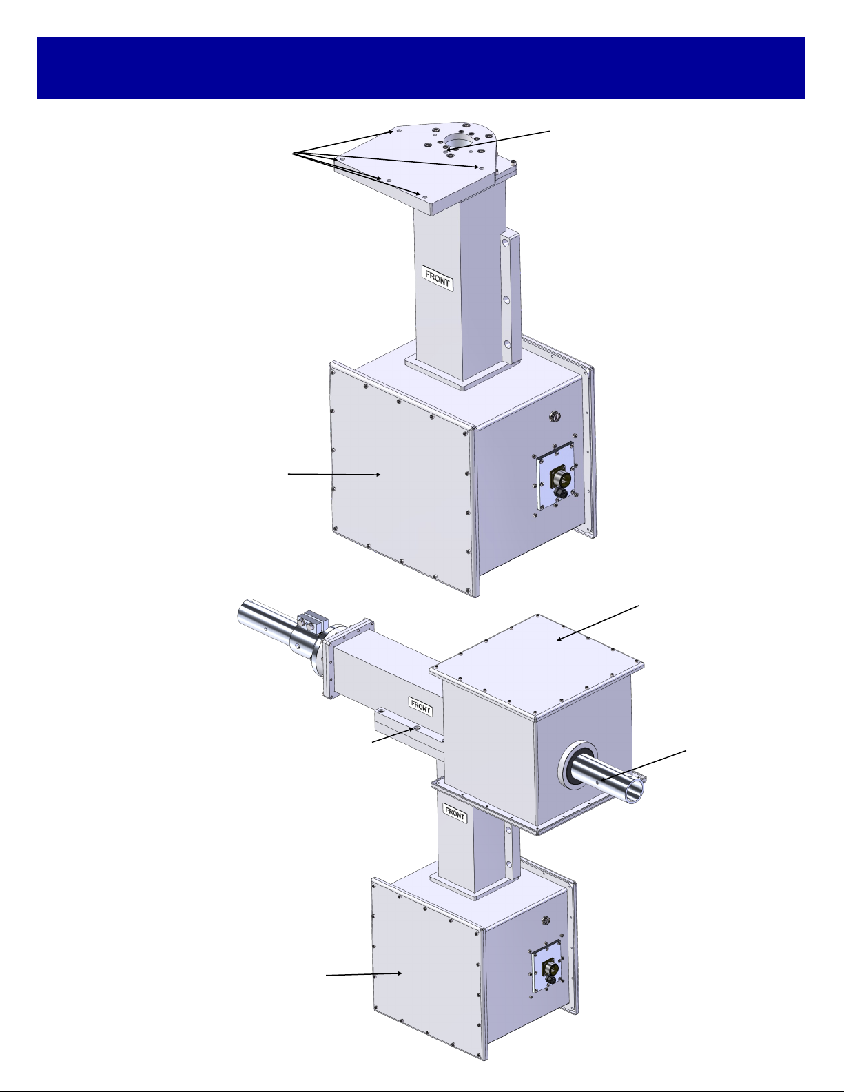
AE1000 ELEVATION ASSEMBLY (SAAE1948) .......................................... 1
AE1000 AZIMUTH ASSEMBLY (SAAE1926) .............................................. 1
7 PIN FEMALE RIGHT ANGLE CONNECTOR ASSEMBLY ....................... 2
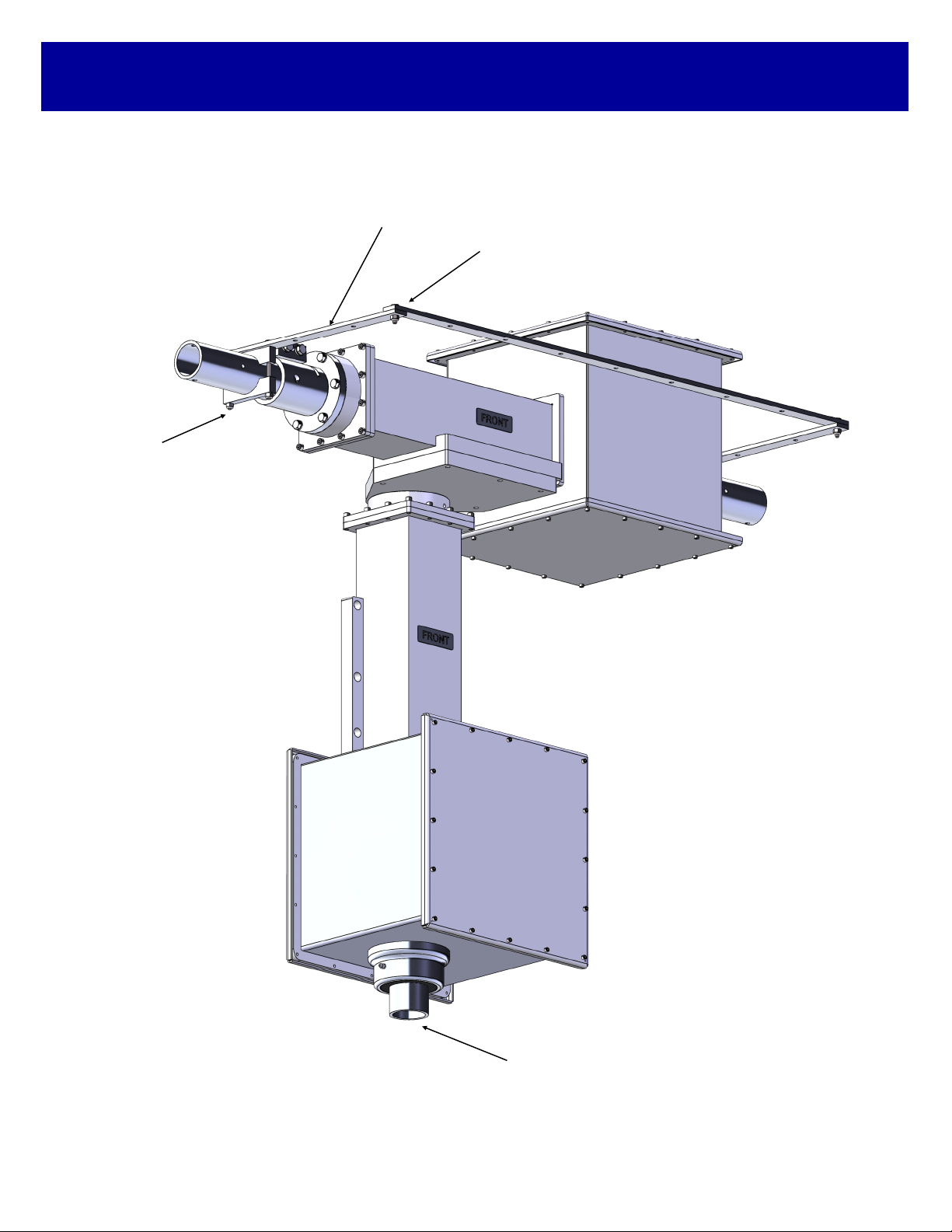
CABLE BRACE (M2AAE1928) .................................................................... 1
CABLE BRIDGE ARM (M2AAE1617) .......................................................... 2
CABLE BRIDGE (M2AAE1618) ................................................................... 1
2.4” CRADLE (M2AMC0128) ....................................................................... 4
PENETROX OR ZINC PASTE (1 OZ. CUP). ............................................... 1
NYLON TIE, 12”........................................................................................... 10
NYLON TIE, 7”............................................................................................. 10
DESICCANT BAG........................................................................................ 2
HARDWARE
BOLT, 3/8-16 X 1.0”, SOCKET HEAD, S.S.................................................. 11
BOLT, 3/8-16 X 3/4”, SOCKET HEAD, S.S.................................................. 1
BOLT, 5/6-18 X 1/2” ,SOCKET HEAD, SS................................................... 2
BOLT, 1/4-20 X 3.5” HEX HEAD S.S. ......................................................... 4
BOLT, 1/4-20 X 1.0” HEX HEAD S.S ........................................................... 2
LOCK NUT, 1/4-20, S.S. .............................................................................. 6
SCREW, 8-32 X 1/2”, SET, S.S. .................................................................. 4
ALLEN KEY, 5/64” ....................................................................................... 1
OPTIONAL KITS
□ PIPE MOUNT KIT, 3” (FGAEPMK3)
DESCRIPTION QTY
3” PIPE CLAMP (M2AMC0144) ................................................................... 3
3” PIPE CLAMP CAP (M2AMC0149)........................................................... 3
3” PIPE STOP (M2AAE1608) ...................................................................... 1
HARDWARE
BOLT, 3/8-16 X 3”, HEX HEAD, S.S............................................................ 6
LOCK WASHER, 3/8”, S.S........................................................................... 6
BOLT, 5/16-18 X 2”, HEX HEAD, S.S. ......................................................... 2
FLAT WASHER, 5/16”, S.S.......................................................................... 2
LOCK NUT, 5/16-18, S.S. ............................................................................ 2
□ PIPE MOUNT KIT, 6” (FGAEPMK6)
DESCRIPTION QTY
6” Pipe Clamp #1 (M2AMC0143) ................................................................. 3
6” Pipe Clamp #2 (M2AMC0142) ................................................................. 3
6” Pipe Stop (M2AAE1606).......................................................................... 1
HARDWARE
Bolt, 3/8-16 x 4”, Hex Head S.S. .................................................................. 6
Lock Washer, 3/8” S.S. ................................................................................ 6
Bolt, 5/16-18 x 2”, Hex Head S.S. ................................................................ 2
Flat Washer, 5/16”, S.S................................................................................ 2
Lock Nut, 5/16-18, S.S. ................................................................................ 2
FGAE1000-D1-W-C-A-H PARTS & HARDWARE

AZ/EL JUNCTION BLOCK CONNECTIONS
The pictures on this page shows the standard wiring in the junction boxes (with switch reversing diodes) & 7 pin
female right angle connector assembly. The system works the following way: Current is constant through the limit
switches and through to the positioner. When the limit switch is activated, it breaks the contact and stops the cur-
rent from continuing. Reversing the positioner in the opposite direction, incorporates directional diodes. Because
this is a standard wiring system, there may be variations to this system that may be changed by your specific ori-
entation of each Axis.
B = GREEN
A = WHITE
D = BLACK
G = BLUE
E = ORANGE

HEATER UNIT CONNECTIONS
Remove the (8) 8-32 screws from the front limit
switch panel.
1/4” Prepare the provided 2-Conductor Red &
Black 16AWG wire. Remove (5-1/4”) of
the outer grey jacket. Strip (1/4”) of
insulation from both the Red & Black
wires as shown.
Slide the prepared 2-Conductor Red & Black 16AWG wire through the cord grip from the front of
the panel. Route the Red wire to position “A” as shown below. Then route the Black wire to
position “B” as shown below. Tighten small flathead screws on the terminal strip. Place the front
panel onto the LSK enclosure and reinstall the (8) 8-32 screws. Tighten the cord grip nut on the
front of the panel.
5”
A
B

FINAL SETUP OF THE LIMIT SET SCREWS:
We have included (2) limit screws, one for each limit switch. The limit screws can be setup at any position based
upon the orientation of your choice. On Azimuth and Elevation use the supplied 8-32 x 1/2” set screws and 5/64
allen wrench. DO NOT INSTALL AT THIS TIME. You can always make slight adjustments to the limit screw if
necessary. We have provided adjustment holes at every 5°. We suggest leaving the cover off of the unit until you
have completed your testing.
LSK-1000 OVERVIEW:
The LSK-1000 limit switch kit is a physical hard backup limit. The standard control unit supplied with our AZ or EL
has “Electronic Limits”, but the LSK-1000 limit switch kit, has been designed as a physical backup system in
the event of a control unit failure. The factory has pre-installed the LSK-1000 limit switch kit into the AZ and EL
units for you. Typically the LSK-1000 limit switches only need to be setup once, but can be adjusted when neces-
sary.
LSK-1000 MANUAL LIMIT SWITCH PRE-TEST:
Remove one half of the black enclosure from the po-
sitioner unit that DOES NOT have cord grips or wires
running into it. You will see the limit switches (A,B) the
limit arm (C), and limit screw (D) as pictured to the
right. We have not installed the limit screw due to
unknown customer orientation. Move the supplied
RC2800 control unit near the positioner for proper limit
switch testing. With the positioner wired to the control
unit, turn the control unit on. Be sure to test the proper
direction of each positioner before moving forward.
Once you have determined the correct direction of ro-
tation from the control units’ “Control Buttons,” deter-
mine which limit switch will be activated by the rotation
of the main gear and limit screw. Press a known direc-
tion using the “Control Buttons,” and manually activate
the limit switch. At this point the positioner should stop
it’s travel. Continue holding the limit switch and re-
verse the direction using the “Control Buttons.” The
motor should move away from the engaged limit
switch. This confirms proper wiring and operation of
the limit switch. Repeat this procedure for the other
direction and limit switch. We suggest, completing
each axis (ie Azimuth and Elevation) prior to moving
onto the final setup.
C
A
B
D
AZ/ EL-1000 LIMIT SWITCH ARANGEMENT
AZ/EL PHYSICAL LIMIT SWITCH TEST

MAINTENANCE INFORMATION
90 day maintenance
1. Visual inspection of complete system, look for rust or corrosion and loose hardware.
2. Manually move each axis individually and LISTEN for smooth operation.
3. Check cables for wear and cracking.
4. Check each axis for physical looseness and or backlash (adjust if necessary).
5. Remove covers, check and clean any excessive foreign debris.
6. Grease main gear and worm gear.
7. Check for proper operation of each axis.
8. Replace covers. The use of silicone grease on the O-ring seals is recommended
1 year maintenance
1. Visual inspection of complete system, look for rust or corrosion and loose hardware.
2. Manually move each axis individually and LISTEN for smooth operation.
3. Check cables for wear and cracking.
4. Check each axis for physical looseness and or backlash (adjust if necessary).
5. Remove covers, check and clean any excessive foreign debris.
6. Check AZ-1000 and EL-1000, thrust block oil-light bearings for wear.
7. Check main load bearings for each individual axis and look for radial slop and or bearing binding.
8. Grease main gear and worm gear.
9. Check physical limit switch operation.
10. Check for proper operation of each axis.
11. Replace covers. The use of silicone grease on the O-ring seals is recommended

TROUBLESHOOTING
Troubleshooting
1. Motors not moving.
A. Check for voltage coming out of control box.
B. Check for voltage at motor (AZ / EL=42 VDC).
C. Check all wiring from control box to motor.
D. Check motor for binding.
2. No pulse from motors.
A. Check all wiring from reed switch to control box.
B. Replace reed switch.
3. Gear binding.
A. Check Gears for Grease.
B. Check gear bolts for looseness.
C. Check gears for foreign debris.
D. Adjust thrust block adjustment.
4. Excess backlash
A. Inspect worm and worm gear for wear.
B. Inspect for thrust block bearing wear.
C. Inspect system for loose hardware.
D. Adjust thrust block adjustment.
5. Excess 3” bearing movement
A. Inspect bearing for radial movement.
B. Replace 3” bearing assembly.
6. 3” Bearing Binding
A. Disassemble bearing assembly and inspect for lubrication and foreign debris.
Reassemble and test. Replace if necessary.
For more complete maintenance and technical assistance, please contact M2 Antenna
Systems, Inc. at (559) 432-8873.

WORM & WORMGEAR ADJUSTMENT
Excessive backlash may develop after
using system for some time. We have
incorporated a built in backlash
adjustment block to keep backlash at a
minimum.
Please review drawings shown for
more detailed information.
To adjust system:
1. Slightly loosen locking bolts to hand
tight.
2. Use a 3/16” Allen wrench to turn
adjustment bolt.
3. One full turn of the adjustment bolt
will move adjustment block 0.010 of an
inch.
4. Clockwise rotation of the adjustment
bolt will move the adjustment block
down, moving the worm closer to the
worm gear and removing backlash.
5. Counter clockwise rotation of the
adjustment bolt will move the
adjustment block up, moving the worm
away from the worm gear and creating
more backlash.
6. Adjustments should be made with
the motor running. Use the motor drive
sound as gauge for friction between
worm and worm gear.
Note: To much friction may cause gear
binding in rarely used sections of the
worm gear. Some finesse maybe
required.
7. Tighten locking bolts and test sys-
tem. Listen for motor running sound for
smooth system operation and minimal
backlash.

COVER SEAL FLANGE MAINTENANCE
1. Remove SET SCREW to prevent excess pressure during insertion of new grease. Insert
new grease into ZERK fitting opposite to SET SCREW.
2. Pump grease into SEAL until a consistent stream of GREASE spills out of hole.
3. Once GREASE can be seen re-insert SET SCREW. CAREFUL not to overfill SEAL as ex-
cess pressure can blow SEAL.
4. Tighten SET SCREW until flush with aluminum housing.
COVER SEAL FLANGE
FILL LINE HOLE WITH
SET SCREW
COVER SEAL FLANGE is used in multiple locations on the AE1000 positioner series depend-
ing on the model purchased. The SEAL comes pre-greased from the factory with LUBRIPLATE MAG
-1. The SEAL may need to be refilled from time to time based on installation environment or usage.
This grease should be inspected and maintained bi-annually.

12 Month Limited Warranty Information
This warranty gives you specific legal rights. You may also have other rights which will vary from state
to state or province to province.
M2 warrants the 2-Axis Positioner unit against defects in material and workmanship for a period of 12
months from date of purchase. During the warranty period, M2 will, at its option, either repair or
replace products or components which prove to be defective. The warranty shall not apply to defects or
damage resulting from:
• Improper or inadequate maintenance by user
• Improperly prepared installation site
• Unauthorized modifications or misuse
• Accident, abuse, or misapplication
• Normal wear
M2 specifically does not warrant this product for any direct, indirect, consequential, or incidental
damages arising from the use or inability to use the product. Some states or provinces do not allow the
exclusion or limitation of liability for consequential or incidental damages so the above limitation may
not apply.
In the event repair or replacement are necessary, purchaser shall contact M2 for return
authorization. In many cases this contact can simplify and expedite the repair / replacement process
and help reduce costs and downtime.
The purchaser shall be responsible for packing the product properly for return and for charges
to ship the product to M2. Always include with the shipment, a statement detailing the problem / failure
and any other pertinent observations. Insuring the product for shipment is recommended. Use the orig-
inal packing materials whenever possible. M2 is responsible for charges (in the United States) to re-
turn the repaired / replacement product only where warranty service is involved.
M2 Antenna Systems, Inc. 4402 N. Selland Ave. Fresno, CA 93722
(559) 432-8873 Fax (559) 432-3059 Web: www.m2inc.com
This manual suits for next models
1
Table of contents
Other M2 Antenna Systems Valve Positioner manuals