DXO Telecom XV1000 User manual

VDSL Modem XV1000
User Guide
-Installation & Operation

Table of Contents
Chapter 1. Introduction........................................................................................................................................1
1. Introduction of XV1000 VDSL Modem.........................................................................................................1
2. Applications................................................................................................................................................1
3. Easy Installation .........................................................................................................................................1
4. Low Cost ....................................................................................................................................................1
5. Application Area .........................................................................................................................................1
6. Name of each part and function ..................................................................................................................2
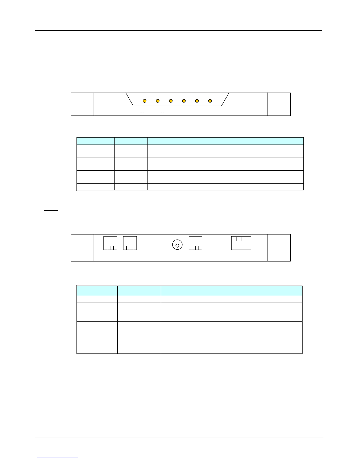
XV1000 VDSL Modem Front Panel .........................................................................................................2
LEDs of XV1000 VDSL Modem...............................................................................................................2
XV1000 VDSL Modem Real Panel ..........................................................................................................2
Function of XV1000 VDSL Modem Port...................................................................................................2
7. XV1000 VDSL Modem Specification...........................................................................................................3
Chapter 2. Before Installation..............................................................................................................................3
1. Safety Check..............................................................................................................................................3
Electrical safety.......................................................................................................................................3
Site of Installation....................................................................................................................................3
2. Telephone Network Service/PC Specification..............................................................................................3
Telephone Network Service.....................................................................................................................3
PC Specification......................................................................................................................................3
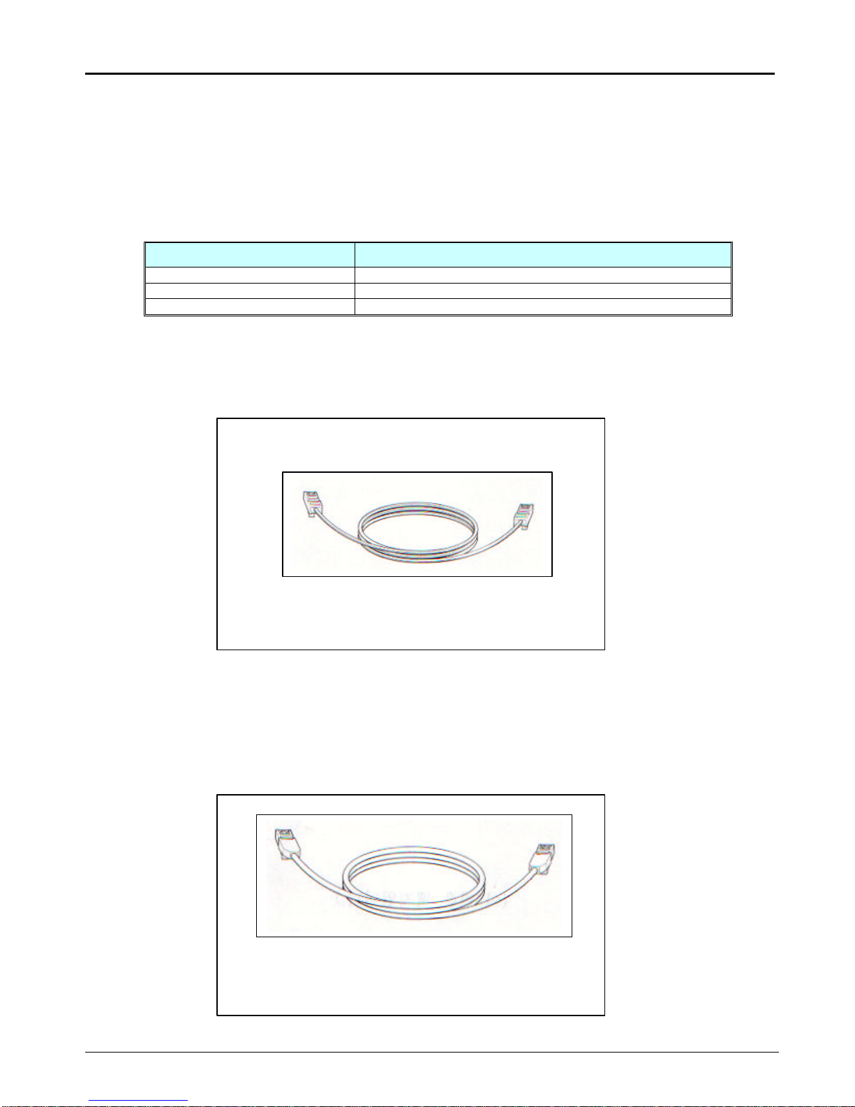
3. Preparing Cables........................................................................................................................................4
Cables used for XV1000 VDSL modem...................................................................................................4
RJ-11 Telephone Cable....................................................................................................................4
RJ-45 UTP Ethernet Cable...............................................................................................................4
Chapter 3. Installing XV1000 VDSL modem........................................................................................................5
1. Environment ...............................................................................................................................................5
2. Packing list.................................................................................................................................................5
3. Modem Installation......................................................................................................................................6
¨çDrawing network configuration diagram............................................................................................6
¨èInstalling the stool............................................................................................................................7
¨éDisconnecting the power cord..........................................................................................................7
¨êConnecting the telephone line..........................................................................................................7
¨ëConnecting the PC...........................................................................................................................8
¨ìApplying power................................................................................................................................8
¨íChecking the connection status........................................................................................................8
VDSL line connection status ............................................................................................................8
PC connection status.......................................................................................................................8
Telephone connection status............................................................................................................9
Chapter 4. Trouble Shooting................................................................................................................................9
1. Items to check before asking for technical support ......................................................................................9
2. Problems and solutions...............................................................................................................................9
Category of problems..............................................................................................................................9
Problems related to power ...............................................................................................................9
Problems related to network connection...........................................................................................9
Chapter 5. Glossary........................................................................................................................................... 10

NOTE : FCC
This equipment has been tested and found to comply with the limits for a Class B digital device,
Pursuant to Part 15 of the FCC rules.
These limits are designed to provide reasonable protection against harmful interface in a residential installation.
This equipment generates, uses and can radiate radio frequency energy and, if not installed and used in
accordance with the instructions, may cause harmful interference to radio communications.
However, there is no guarantee that interference will not occur in a particular installation.
If this equipment does cause harmful interference to radio or television reception, which can be determined by turning
the equipment off and on, the user is encouraged to try to correct the interference by one or more of the following
Measures:
--Reorient or relocate the receiving antenna.
--Increase the separation between the equipment and receiver.
--Connect the equipment into an outlet on a circuit different from that to which the receiver is connected.
--Consult the dealer or an experienced radio/TV technician for help.
CAUTION: Changes or modifications not expressly approved by the manufacturer responsible for compliance could void the
user’s authority to operate the equipment
NOTE : UL
Do not use upside down.
Operator or installer must remove power and TNV connections before handling the equipment.
Caution –To reduce the risk of fire, use only No. 26 AWG or larger telecommunication line cord.

XV1000 Modem User Guide
1
Chapter 1. Introduction
This chapter explains major features, operation procedure, hardware configuration and specification of XV1000, the
DXO VDSL Modem.
lIntroduction of XV1000 VDSL Modem
lName and function of each part
lSpecification of XV1000
1. Introduction of XV1000 VDSL Modem
XV1000 VDSL modem allows the PC to connect to the internet or other multimedia service network using the
conventional telephone network (PSTN).
Unlike the ADSL modem, XX1000 provides 10Mbps data transmission rate. Telephone conversation is never
interrupted while the modem is in use.
Features that XV1000 offers are as follows:
2. Applications
Features that XV1000 offers include connection to the internet, interactive communication, e-mails, file transfer,
download/upload of motion pictures and others.
3. Easy Installation
Installation of XV1000 is so simple that users can connect to ISP’s and enjoy the internet service very easily.
4. Low Cost
XV1000 VDSL modem uses the conventional telephone network (PSTN) so there is no need for huge amount
of money nor time required for building new infra-structure installation often required for other type of
technologies, like optical cable network. Therefore XV1000 is a very cost effective solution.
5. Application Area
VDSL has many application area and offers business opportunities for high speed internet service providers, e-
commerce, construction companies and MDU -hotel, apartment complex, office buildings and campus.

XV1000 Modem User Guide
2
6. Name of each part and function
Front
XV1000 VDSL Modem Front Panel
LEDs of XV1000 VDSL Modem
Indication Color Function
PWR green lit while AC input power is normal.
SYNC green lit while connected to the VDSLAM
CHK red flashes when error occurs in data communication with
VDSLAM
LINK green lit while connected to the PC
RD green flashes while data is received from the PC
TD green flashes while data is received from the VDSLAM
Rear
XV1000 VDSL Modem Real Panel
Function of XV1000 VDSL Modem Port
Indication Port Function
TEL Telephone Telephone is connected.
LINE VDSL line RJ-11 cable is used to connect the modem to the
telephone socket on the wall.
VDSL data is received/transmitted over this port.
DC 5V Power input Power adaptor (AC 110V/220V, DC/5V) is connected.
MON Serial
(RS232C) This port is used by the service personnel for the
maintenance of the modem.
10/100Base-T
Ethernet PC LAN card is connected using UTP Category-3,4,5
Straight-through cable. 10/100Mbps speed is supported.
PWR SYNC CHK LINK
RD TD
XV 1000
TEL LINE DC 5V MON 10/100Base-T

XV1000 Modem User Guide
3
7. XV1000 VDSL Modem Specification
Item Specification
Modulation QAM
Duplexing FDD
Data Transmission Symmetric/Asymmetric
Speed (DSLAM-Modem)Downstream: max 10 Mbps, Upstream: max 10 Mbps
Standards ANSI T1E1.4, VDSL Coalition, FSAN
Ethernet Port : RJ-45 (10/100Base-T)
POTS Line : RJ-11
VDSL Line : RJ-11
Interface
Console Port : RJ-11
Error detection Reed-Soloman
Size 152 (w) x 172(d) x 32(h)(unit: mm)
Input : AC 110/220V
Frequency : 50/60 Hz
Power Output : 5V DC
Chapter 2. Before Installation
Explained in this chapter are issues that users should take note of before installing the modem.
This chapter includes the following sections:
lSafety Check
lBefore installation
lPreparing cables
1. Safety Check
The following items should be checked before the installation and use of the modem.
Electrical safety
lCustomers shall not disassemble the unit in any case, especially when the power is being applied.
lEnsure that there are no such matters that may pose danger to the installer in the installation area:
wet floor, ungrounded cable, worn-out power cords, floor without proper ground.
l“This equipment does not directly connected to ISDN/PSTN line”
l“This equipment should be connected to XV2000 only.”
Site of Installation
lDuring the operation of electrical devices, heat is inevitable. Ensure that the device is installed in such
an environment that proper ventilation will be able to dissipate heat, otherwise the device may not
function properly.
2. Telephone Network Service/PC Specification
Telephone Network Service
XV1000 VDSL modem is to be used in areas where telephone network service is provided.
Users already subscribed to the telephone service can use the telephone line as it is. New users need
to ask the regional telephone company for the telephone service and should have lines installed.
PC Specification
To connect XV1000 to the PC, a LAN card (10Base-t or 10/100Base-T) must be installed inside the PC.

XV1000 Modem User Guide
4
3. Preparing Cables
To connect XV1000 to the network, the following cables are required for each port.
Cables used for XV1000 VDSL modem
port cable
Telephone line RJ-11 cable
Ethernet (10/100Base-T) RJ-45 UTP category-3,4,5 Straight-through cable
Console RJ-11 cable
RJ-11 Telephone Cable
One end of the RJ-11 telephone cable is connected to the telephone line port at the rear panel of the
XV1000 and the other end is connected to the telephone.
RJ-45 UTP Ethernet Cable
One end of RJ-45 UTP Ethernet cable is connected to the Ethernet port (10/100Base-T) at the rear panel
of XV1000 and the other end is connected to the LAN card of the PC.
RJ-11 Telephone cable
RJ-45 Ethernet cable

XV1000 Modem User Guide
5
Cables may look alike but they can be of totally different type or they may have different pin configuration. To
avoid any confusion, attach labels to the cables for the XV1000 so that cables for XV1000 and other electrical
equipments will not mix.
Chapter 3. Installing XV1000 VDSL modem
This chapter explains the environment where the XV1000 can be installed and the method to install and connect
the modem to the network.
This chapter includes the following sections:
lInstallation environments
lPacking list
lModem installation
1. Environment
Operating Temperature : 0 ~ 45°C
Relative Humidity : 10 ~ 95 % (non-condensing)
Power Consumption : 2.5 Watts (max)
AC Power Input Voltage : AC 110/220V
AC Power Input Frequency
:50/60 Hz
2. Packing list
Please ensure that the following materials are included in the packing box.
¨XV1000 VDSL modem
¨Stool for the modem
¨Power adaptor
¨RJ-11 telephone cable
¨RJ-45 UTP Ethernet cable
¨User Guide
XV1000 VDSL modem Stool for the modem Power adaptor
RJ-11 Phone Cable User Guide RJ-45 UTP Ethernet Cable
Materials included in the package

XV1000 Modem User Guide
6
3. Modem Installation
Following is the procedure to configure the network using XV1000.
¨çDrawing network configuration diagram.
¨èInstalling the stool.
¨éDisconnecting the power cord
¨êConnecting the telephone cable
¨ëConnecting the PC
¨ìApplying the power
¨íChecking the connection status
¨ç
Drawing network configuration diagram
It is recommended that the network configuration diagram be drawn first before the actual installation.
The following issues must be taken into consideration.
lWhat is the purpose of using XV1000?
lWill the XV1000 and telephones be used together?
lAll the equipment necessary are ready? (PC, telephone, network cable and others)
The following figure is an example of VX1000 connected to the PC and the telephone. Please draw your
own diagram appropriate for your purpose.
Example: Network configuration diagram
AC 110-220V
XV1000
VDSL DSLAM

XV1000 Modem User Guide
7
¨è
Installing the stool
To use the XV1000 in its vertical position, install the stool at the side of the modem in the following manner.
1. XV1000 VDSL modem has groove at the right rear side. Slide the stool into the groove..
2. When installed correctly, the printed letters ‘VDSL’can be read. If the stool is inserted in the
wrong side, then the letters are placed upside-down.
¨é
Disconnecting the power cord
Unplug the adaptor jack from the power input port to disconnect power to the modem, or unplug the
power cord of the adaptor from the AC power outlets.
¨ê
Connecting the telephone line
1. Unplug the telephone lines from the wall in the room and plug it into the line port of XV1000
modem.
2. Connect one end of the RJ-11cable to the telephone and the other to the telephone port of
XV1000 modem.
Mounting the stool

XV1000 Modem User Guide
8
¨ë
Connecting the PC
Connect one end of the RJ-45 UTP Ethernet cable to the Ethernet port (10/100Base-T) of XV1000
and the other to the LAN card of the PC.
The PC connected to the XV1000 should have LAN card supporting 10Mbps or 10/100Mbps. Please
refer to the manuals provided with the LAN card for details on installing the LAN card into the PC.
¨ì
Applying power
Connect the power adaptor to the XV1000 modem power input port (DC 5V) and plug the power cable
into the power outlet. Now the installation is completed.
Only the power adaptor provided with the XV1000 modem shall be used.
¨í
Checking the connection status
The cable connection to each XV1000 modem port can be checked and verified in the following way.
VDSL line connection status
VDSL line connection is successful if the SYNC LED is lit within a few seconds after power is applied to
the XV1000 modem.
PC connection status
PC connection is successful if the LINK LED of the XV1000 modem and the LINK LED on the LAN card
of the PC turn on green.
Connecting the PC

XV1000 Modem User Guide
9
Telephone connection status
Telephone connection is successful if normal dial tone is heard when the handset is lifted and if speech
can be heard without cross-talk during the conversation over the phone.
Chapter 4. Trouble Shooting
This chapter explains problems that may arise during the operation and suggests solutions.
This chapter include the followings:
lItems to check before asking for technical support
lProblems and solutions
1. Items to check before asking for technical support
Please ask for technical support if problems occur while in use that cannot be resolved by customers.
The followings need to be checked by users before contacting the technical support group.
lProduct model name
lProduct serial number
lDate of product installation
lProblem description
lActions taken by customers to resolve the problem and the results
2. Problems and solutions
Problems that may arise are categorized with explanations and the solutions are suggested.
Category of problems
lProblems related to power
lProblems related to network connection
Problems related to power
üPWR LED does not turn on green after the power adaptor is connected and power cable is plugged
into the power outlet
Check followings:
¨Check power outlet.
¨Unplug the power jack from the power input port (DC 5V) at the rear panel of the XV1000 modem and
plug the jack again.
If the problem does not get resolved, please remove the jack from the power input port of XV1000 right
away and call the service center.
Problems related to network connection
üInternet connection fails.
üSYNC or LINK LED does not turn on.
Please check the followings:
¨Check the cable connection between the XV1000, telephone and PC.
¨Check the status of the LAN card of the PC.
¨Check if the PC itself is working properly.

XV1000 Modem User Guide
10
¨Check if the IP address is correct for the network connection service.
If the problem does not get resolved, please remove the jack from the power input port of XV1000 right
away and call the service center.
Chapter 5. Glossary
10Base-TA 10 Mbps Ethernet LAN that runs over twisted-pair wiring. This network interface was originally
designed to run over ordinary twisted-pair (phone wiring) but is predominantly used with Category
3 or Category 5 cabling.
VDSL Very High Data Rate Digital Subscriber Line
VDSL can service both voice and high speed data simultaneously.
A technology that delivers 13 to 52 Mbps downstream and 1.5 to 2.3 Mbps upstream over a single
copper twisted-pair. The operating range of VDSL is limited to 1,000 to 4,500 feet (304.8 to 1,372
meters) from the CO.
Ethernet A type of network that supports high-speed communication among systems. It is a widely
implemented standard for LANs developed by Xerox, Intel and DEC. All hosts are connected to
a coaxial cable where they contend for network access using a Carrier Sense, Multiple Access
with Collision Detection (CSMA/CD) paradigm.
IP Address Any computing device that uses the Internet must be assigned an Internet or IP address. This 32-
bit number is written in 4 decimal fields or "octets" separated by periods, e.g., 192.9.200.1. All
workstations on a given IP network use the same IP network number, and each workstation has a
unique IP host address and an optional subnetwork number. The network and subnetwork
numbers together are used for routing, while the host number is used to address an individual
host within the network or subnetwork. A subnet mask may be used to extract network and
subnetwork information from the IP address.
Switch Switch is a device that filers and transmits frame according to the destination address of
each frame. Switch operates in the data link layer of the OSI layer model.
TCP/IP
(Transmission
Control
Protocol/Internet
Protocol)
Transmission Control Protocol/Internet Protocol. The dominant protocol suite in the worldwide
Internet, TCP allows a process on one machine to send data to a process on another machine
using the IP. TCP can be used as a full-duplex or one-way simplex connection.
PSTN Public Switched Telephone Network. A network shared among many users who can use
telephones to establish connections between two points. Also known as dial network.
POTS
(Plain Old Telephone
Service)
Plain Old Telephone Service.
Standard telephone service over the PSTN, with an analog bandwidth of less than 4 KHz. This
term commonly refers to standard telephony, as in placing and receiving telephone calls. This is
more or less interchangeable with PSTN (Public Switched Telephone Network). A POTS splitter
enables both DSL digital data and standard telephone analog transmissions to share a single
connection.
The only name recognized around the world for basic analog telephone service. POTS takes the
lowest 4kHz of bandwidth on twisted pair wiring. Any service sharing a line with POTS must either
use frequencies above POTS or convert POTS to digital and interleave with other data signals.

XV1000 Modem User Guide
11
WW
(World Wide Web) An Internet facility that links documents locally and remotely. The Web document, or
Web page, contains text, graphics, animations and videos as well as hypertext links.
The links in the page let users jump from page to page (hypertext) whether the pages
are stored on the same server or on servers around the world. Web pages are accessed
and read via a Web browser, the two most popular being Internet Explorer and
Netscape Navigator.. In the last half of the 1990s, the Web became "the" center of
Internet activity, because the Web browser provided an easy, point and click interface to
the largest collection of online information in the world. Ever since the Web became the
focal point of the Internet, the amount of information has increased at a staggering rate.
The Web has also turned into an online shopping mall as almost every organization has
added e-commerce capabilities. In addition, the Web has become a multimedia delivery
system as new browser features and plug-in extensions allow for audio, video,
telephony, 3-D animations and videoconferencing. Most browsers also support the Java
language, which allows applications to be downloaded from the Net and run locally.
The www. prefix used on most Web addresses is actually the mnemonic name of the
Web server used at the Web site. Most Webmasters name their servers WWW in order
to provide a recognizable address for everyone. Web addresses (URLs) are read from
right to left, so that the WWW is the last component of the address, which is the name
of the Web server itself.
Table of contents
Popular Modem manuals by other brands

Sierra Wireless
Sierra Wireless AirCard 503 user manual

D-Link
D-Link DSL-520B Specifications

Scientific Atlanta
Scientific Atlanta WebSTAR DPX110 user guide

CAMBRON
CAMBRON MusicOne Stick user guide

Mitsubishi Electric
Mitsubishi Electric MIM-A01 instruction manual

NexComm Systems
NexComm Systems N560 series H/W installation guide