Table of Figures
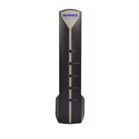
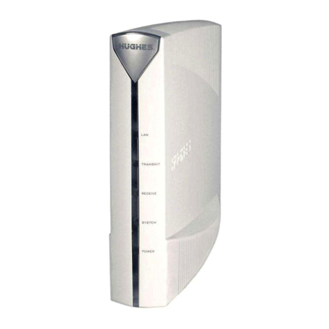
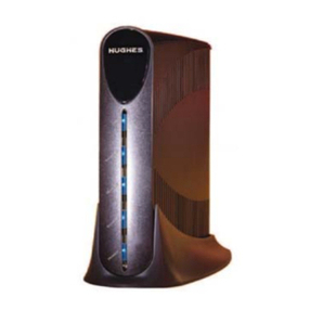
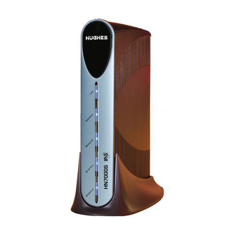
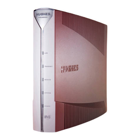
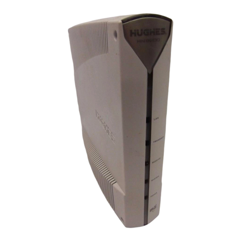
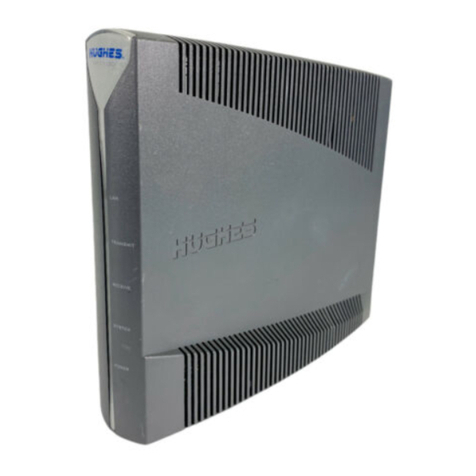
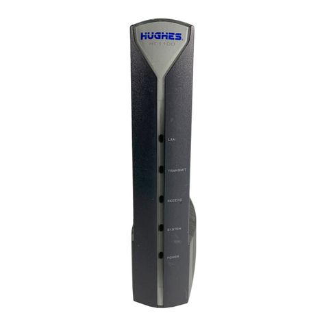
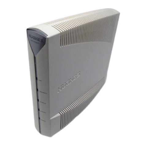
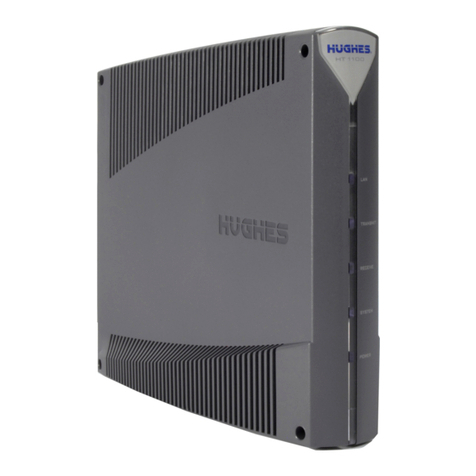
Figure 1: HN9000 satellite modem .................................................................................................................................3
Figure 2: Single-host conguration..................................................................................................................................4
Figure 3: Multiple-host conguration in an Ethernet wired LAN...................................................................................4
Figure 4: Private network conguration..........................................................................................................................5
Figure 5: Satellite modem installation summary..............................................................................................................8
Figure 6: Power supply for the HN9000 satellite modem..............................................................................................10
Figure 7: Internet Protocol Properties dialog.................................................................................................................13
Figure 8: Settings for primary and alternate addresses on the laptop............................................................................15
Figure 9: HN9000 in vertical position............................................................................................................................18
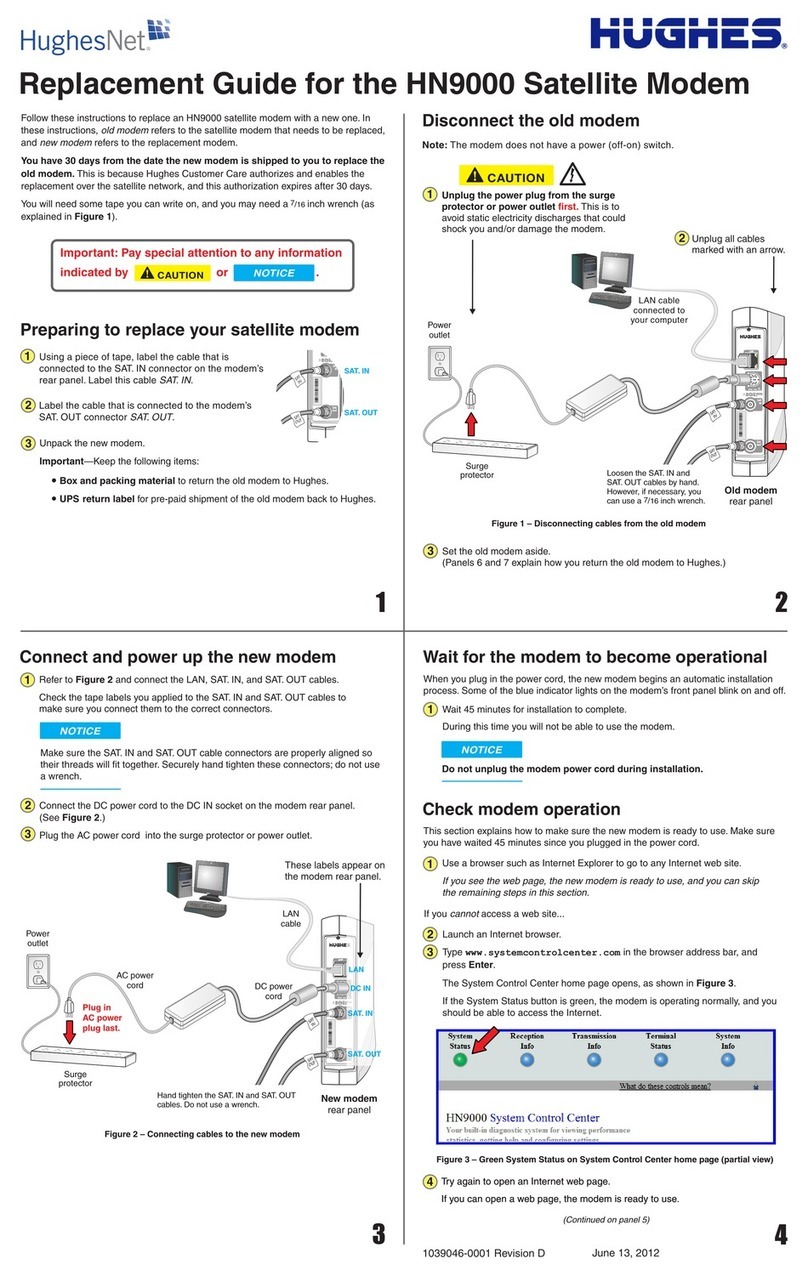
Figure 10: Powering up the modem...............................................................................................................................19
Figure 11: Connecting the installer's laptop computer to the modem............................................................................20
Figure 12: System Control Center home page...............................................................................................................21
Figure 13: Icon for opening Advanced Pages................................................................................................................21
Figure 14: Installation screen.........................................................................................................................................22
Figure 15: Example of a GPS receiver display..............................................................................................................23
Figure 16: Terminal Pointing Info screen.......................................................................................................................24
Figure 17: In-line connection of the DAPT ...................................................................................................................28
Figure 18: Connecting the transmit and receive cables..................................................................................................29
Figure 19: Terminal Initialization Sequence in progress................................................................................................32
Figure 20: Terminal Initialization Sequence complete ..................................................................................................33
Figure 21: Terminal Initialization Sequence screen (top part).......................................................................................42
Figure 22: Activation link on System Control Center home page.................................................................................43
Figure 23: Ethernet and other cables (nal conguration)............................................................................................43
Figure 24: Activation link on the customer’s computer.................................................................................................44
Figure 25: Subscriber agreement....................................................................................................................................45
Figure 26: Subscriber agreement with SAN and PIN elds..........................................................................................46
Figure 27: Welcome screen............................................................................................................................................46
Figure 28: Downloading Software screen......................................................................................................................47
Figure 29: Computer veried screen..............................................................................................................................48
Figure 30: Congure Software (HughesNet Tools) screen............................................................................................48
Figure 31: Implement Public IP? screen........................................................................................................................49
Figure 32: Activation Complete screen..........................................................................................................................49
Figure 33: Icon for creating shortcut..............................................................................................................................56
Figure 34: System Control Center home page...............................................................................................................57
Figure 35: Common features on System Control Center screens..................................................................................58
Figure 36: System Control Center button links..............................................................................................................59
Figure 37: Icon for accessing the Advanced Pages........................................................................................................60
Figure 38: Format of status and information screens.....................................................................................................61
Figure 39: Example of a state code................................................................................................................................61
Figure 40: Red ag problem indicator...........................................................................................................................62
Figure 41: System Status page.......................................................................................................................................62
vii
