Dyaco XT510-AT34 User manual

X
XT
T5
51
10
0-
-A
AT
T3
34
4
1
11
10
0v
v
T
Tr
re
ea
ad
dm
mi
il
ll
l
S
Se
er
rv
vi
ic
ce
e
M
Ma
an
nu
ua
al
l

WARNING:
ALWAYS UNPLUG THE TREADMILL FROM THE ELECTRICAL
OUTLET BEFORE SERVICING THE UNIT.

S
Se
er
rv
vi
ic
ce
e
M
Ma
an
nu
ua
al
l
T
Ta
ab
bl
le
e
o
of
f
C
Co
on
nt
te
en
nt
ts
s
T
Ta
ab
bl
le
e
o
of
f
C
Co
on
nt
te
en
nt
ts
s
1
1
TABLE OF CONTENTS
Table of Contents...................................................................... 1
Table of Figures ........................................................................ 3
Description................................................................................ 4
AE
LECTRICAL
C
ONFIGURATION
....................................... 4
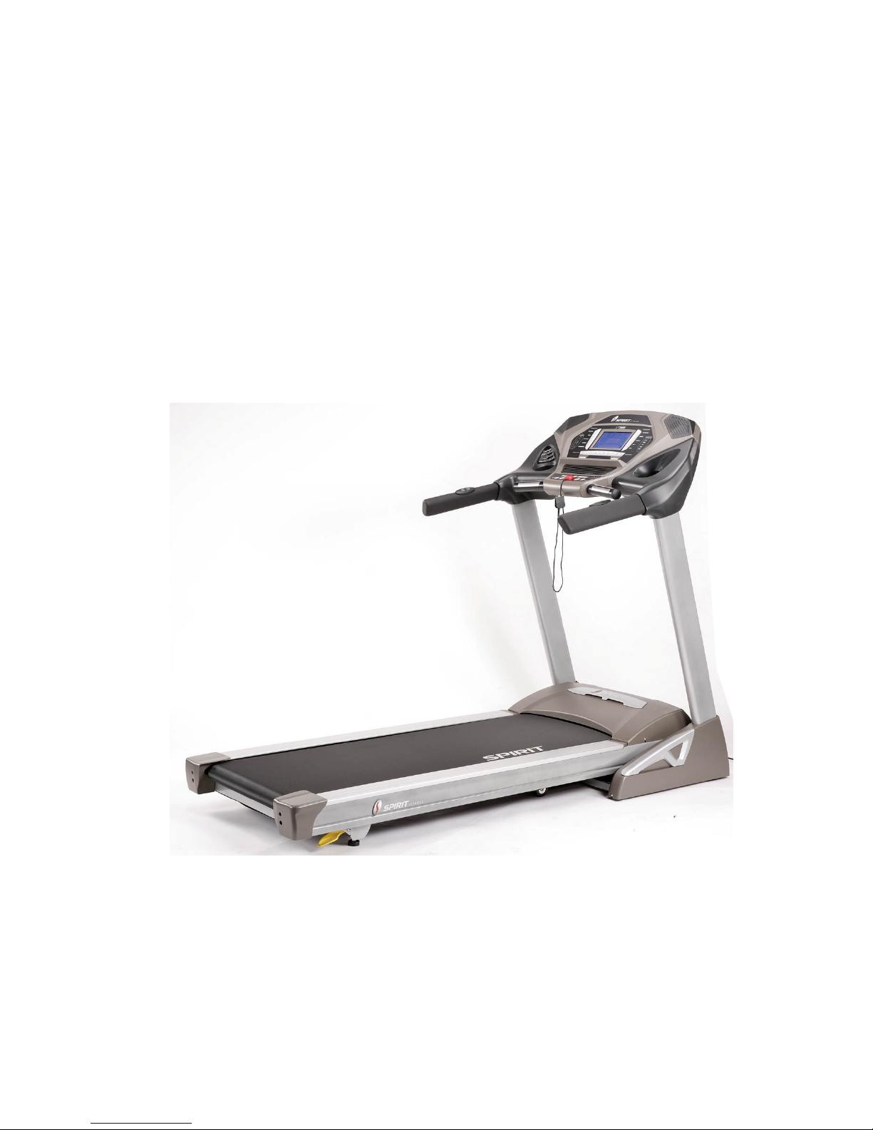
1. xt510-at34 Treadmill components ................................ 4
B.
G
ENERAL
I
NFORMATION
................................................. 5
1. Console ...................................................................... 5
2. Main controller.............................................................. 5
3. Treadmill motor ............................................................ 5
4. Incline motor................................................................. 5
Operation................................................................................... 7
AW
INDOW
D
ISPLAY
M
ODE
............................................... 7
1. OFF Mode..................................................................... 7
2. READY Mode .............................................................. 7
3. SLEEP Mode ................................................................ 7
4. RUN Mode.................................................................... 7
BF
UNCTION
........................................................................ 8
1. SPEED .......................................................................... 8
2. Incline ........................................................................... 8
3. TIME............................................................................. 8
4. LAPS............................................................................. 9
5. DISTANCE................................................................... 9
6. CALORIES ................................................................... 9
7. PULSE .......................................................................... 9
CF
UNCTION
B
UTTON
I
N
M
AIN
M
ODE
............................. 10
1. READY MODE .......................................................... 10
2. RUN MODE ............................................................... 11
D
C
ALIBRATION
P
ROCEDURE ................................. 12
1. Calibration................................................................... 12
Troubleshooting ...................................................................... 13
1. General........................................................................ 13

S
Se
er
rv
vi
ic
ce
e
M
Ma
an
nu
ua
al
l
T
Ta
ab
bl
le
e
o
of
f
C
Co
on
nt
te
en
nt
ts
s
T
Ta
ab
bl
le
e
o
of
f
C
Co
on
nt
te
en
nt
ts
s
2
2
2. Troubleshooting Matrix .............................................. 14
3. controller debugging form .......................................... 21
Diagrams and Schematics ....................................................... 22
APPENDIX A......................................................................... 26
1. TREADBELT ADJUSTMENT.................................. 26
APPENDIX B ......................................................................... 28
1. TREADMILL LUBRICATION ................................. 28
APPENDIX C ......................................................................... 29
1. RESET SWITCH RESETTING ................................. 29
APPENDIX D......................................................................... 30
1. FUSE REPLACEMENT............................................. 30
APPENDIX E ......................................................................... 31
1. SPEED SENSOR ADJUSTMENT............................. 31
2. SERVICE QUESTIONS............................................. 31

S
Se
er
rv
vi
ic
ce
e
M
Ma
an
nu
ua
al
l
T
Ta
ab
bl
le
e
o
of
f
F
Fi
ig
gu
ur
re
es
s
T
Ta
ab
bl
le
e
o
of
f
F
Fi
ig
gu
ur
re
es
s
3
3
TABLE OF FIGURES
Figure 1 Operational Flowchart ............................................... 6
Figure 2 Console Layout........................................................ 22
Figure 3 Mechanical Layout .................................................. 22
Figure 4 Main Controller information & voltages................. 23
Figure 5 Function JK1 connector on Main Controller........... 23
Figure 6 Wiring Diagram....................................................... 24
Figure 7 Schematic Diagram ................................................. 25
Figure 8 If Treadbelt slips...................................................... 26
Figure 9 If tread belt shifts too far to the Right ..................... 26
Figure 10 If tread belt shifts too far to the Left...................... 27
Figure 11 Resetting Reset switch........................................... 29
Figure 12 Fuse replacement................................................... 30

S
Se
er
rv
vi
ic
ce
e
M
Ma
an
nu
ua
al
l
D
De
es
sc
cr
ri
ip
pt
ti
io
on
n
D
De
es
sc
cr
ri
ip
pt
ti
io
on
n
4
4
DESCRIPTION
A E
LECTRICAL
C
ONFIGURATION
Note: Electrical servicing of this treadmill is limited to board
level replacement.
1. XT510-AT34 TREADMILL COMPONENTS
a) Safety key:
To fits on the Console that activate all functions. If no safety
key, console can not be controlled.
b)Console:
Interface that controls all functions of the treadmill.
c) Main controller:
The circuit board consist of the DC power supply for
consol
e、
incline drive
r
and DC motor driver, link the
console to output appropriate voltages for motor that
control the treadmill functions.
d)Treadmill motor:
This is a variable speed for DC motor. To control the 0 –90
voltages on the main controller, it can to increase or
decrease speed of running belt.
e) Incline motor:
This is an ac motor. User can to control variable
elevation by console within main controller.

S
Se
er
rv
vi
ic
ce
e
M
Ma
an
nu
ua
al
l
D
De
es
sc
cr
ri
ip
pt
ti
io
on
n
D
De
es
sc
cr
ri
ip
pt
ti
io
on
n
5
5
B.
G
ENERAL
I
NFORMATION
1. CONSOLE
f) Contains control pad and LCD Display.
2. MAIN CONTROLLER
a) Include power supply
、
motor driver control circuit and incline
control circuit.
3. TREADMILL MOTOR
a) It’s a variable speed on 0-90 volt DC motor.
b)Have three wires red, black and green.
c) If there is DC voltage on the Red wire (M+) the treadmill motor
will turn clockwise.
d)If there is DC voltage on the Black wire (M-) the treadmill motor
will turn counter-clockwise.
e) The higher the voltage the faster the motor turns.
f) The green wire is ground.
4. INCLINE MOTOR
a) This is a 110 volt AC motor.
b)Have four wires, red, black, white and green.
c) Has one 3 pins cable of position sensor.
d)If there is AC voltage on the Red wire (UP) the incline motor will
increase the incline.
e) If there is AC voltage on the Black wire (DOWN) the incline
motor will decrease the incline.
f) The White wire (COM) is neutral.

S
Se
er
rv
vi
ic
ce
e
M
Ma
an
nu
ua
al
l
D
De
es
sc
cr
ri
ip
pt
ti
io
on
n
D
De
es
sc
cr
ri
ip
pt
ti
io
on
n
6
6
Figure 1 Operational Flowchart

S
Se
er
rv
vi
ic
ce
e
M
Ma
an
nu
ua
al
l
O
Op
pe
er
ra
at
ti
io
on
n
O
Op
pe
er
ra
at
ti
io
on
n
7
7
OPERATION
A W
INDOW
D
ISPLAY
M
ODE
1. OFF MODE
a) When user doesn’t insert the SAFETY KEY on the console, the
treadmill enters the OFF Mode and all windows will appear
blank.
2. READY MODE
a) When the treadmill is ON and SAFETY KEY is inserted in
console, the message window will show “PRESS START FOR
QUICK START OR PROGRAM BUTTON FOR SETUP”
b)Press START button to start treadmill on Manual program.
3. SLEEP MODE
a) In SLEEP Mode, if anyone
button is pressed then the treadmill
enters READY Mode.
4. RUN MODE
a) In RUN Mode, pressing the “STOP” button and removing the
SAFETY KEY will cause the treadmill stop instantly and enter
OFF Mode.

S
Se
er
rv
vi
ic
ce
e
M
Ma
an
nu
ua
al
l
O
Op
pe
er
ra
at
ti
io
on
n
O
Op
pe
er
ra
at
ti
io
on
n
8
8
B F
UNCTION
1. SPEED
a) Display the current speed in mile per hour.
b)DISPLAY range is 0.0 to 99.9 mph.
c) WORK range is 0.5 to 12.0 mph.
d)Press “FAST” or ”SLOW” to adjust speed, each increment and
decrement is 0.1 mph.
2. INCLINE
a) Display the incline position from 0 to 15.
b)DISPLAY range is 0 to 999.
c) WORK range is 0 to 15.
d)INCLINE preset value is 0 to 15.
e) Press “UP” or ”DOWN” to adjust incline, each increment and
decrement is 1.
3. TIME
a) TIME is either COUNT UP or COUNT DOWN. System preset
is COUNT UP; if user sets the time then timer is COUNT
DOWN.
b)DISPLAY range is 0:00 to 99:99.
c) WORK range is 0:00 to 99:59.
d)COUNT DOWN setup range is 10:00 to 99:00.
e) When TIME is set, the count will go to zero.
f) In RUN Mode, press “STOP” button to save value of time and
enter “RUN Mode” again that value will continue count up time.

S
Se
er
rv
vi
ic
ce
e
M
Ma
an
nu
ua
al
l
O
Op
pe
er
ra
at
ti
io
on
n
O
Op
pe
er
ra
at
ti
io
on
n
9
9
4. LAPS
a) Display the total working lap quantity.
b)DISPLAY range is 0 to 99.
c) WORK range is 0 to 99.
d)One lap of Playground is 0.25 Mile
5. DISTANCE
a) Display the current distance in mile.
b)DISPLAY range is 0.00 to 99.99.
c) WORK range is 0.00 to 99.99.
6. CALORIES
a) Displays the cumulative calories burned at any given time during
your workout.
b)DISPLAY range is 0.0 to 999.0.
c) WORK range is 0.0 to 999.0.
7. PULSE
a) Displays the heart rate beat by using hand pulse or receiver.
When use receiver, a chest belt must be worn.
b) DISPLAY range is 0 to 999.
c) WORK range is 50 to 220.
d)In RUN Mode, if the treadmill doesn’t have a signal for 8
seconds then display value will become “ --- ”.

S
Se
er
rv
vi
ic
ce
e
M
Ma
an
nu
ua
al
l
O
Op
pe
er
ra
at
ti
io
on
n
O
Op
pe
er
ra
at
ti
io
on
n
1
10
0
C F
UNCTION
B
UTTON
I
N
M
AIN
M
ODE
1. READY MODE
a) SAFETY KEY: Fit safety key in right position to power on the
computer. When safety key is pulled away from it’s position, the
computer will be automatically shut down.
b)STOP button: Non-function.
c)
START
button: Pressing “
START
” button to start treadmill,
when pressing “
START
” button, there will be 3 second final
count down on window display, then machine starts running in
MANUAL.
d)ENTER button: Press “ENTER” button to change each function.
MANUAL can set using time, Pre-set PROGRAM can set using
time and speed, Heart Rate Control 1~2 can set time, age and the
value of heart rate. User Program 1~2 can set time, speed and
incline.
e) PROGRAM button: Press PROGRAM button to select manual,
preset program, user program and heart rate control program.
f) FAST button: If user doesn’t enter a setting then this button is
non-functional.
g)SLOW button: If user doesn’t enter a setting then this button is
non- functional.
h)UP button: If user doesn’t enter a setting then this button is non-
functional.
i) DOWN button: If user doesn’t enter a setting then this button is
non- functional.
j) FAN button: It can to control ON/OFF for the fan.
k)Disable button: It can to control handle bar switch for ON/OFF.

S
Se
er
rv
vi
ic
ce
e
M
Ma
an
nu
ua
al
l
O
Op
pe
er
ra
at
ti
io
on
n
O
Op
pe
er
ra
at
ti
io
on
n
1
11
1
2. RUN MODE
a)
SAFETY KEY: When safety key is pulled away from it’s
position, the computer will be automatically shut down.
b)STOP button: press “STOP” button to stop treadmill.
c) START button: non-functional.
d)ENTER button: to display exercise data
e) Program button: non-functional.
f) FAST button: Press the button to increase your speed and each
increase is 0.1mph (kmph). If button is pressed continuously then
speed increases to MAX SPEED quickly.
g)SLOW button: Press the button to decrease your speed and each
decrease is 0.1mph (kmph). If button is pressed continuously
then speed decreases to MIN SPEED quickly.
h)UP button: Press the button to raise position and each increase is
1, the maximum incline position is 15.
i) DOWN button: Press the button to lower position and each
decrease is 1, the minimum incline position is 0.
j) Fan button: It can to control ON/OFF for the fan.
k)Disable button: It can to control handle bar switch for ON/OFF.

S
Se
er
rv
vi
ic
ce
e
M
Ma
an
nu
ua
al
l
O
Op
pe
er
ra
at
ti
io
on
n
O
Op
pe
er
ra
at
ti
io
on
n
1
12
2
D
C
ALIBRATION
P
ROCEDURE
1. CALIBRATION
a) Turn on power.
b) First, to put safety key on right position, then Press “START”
and “FAST” button at the same time.
c) The screen will to show” FACTORY SETTING PRESS
NETER” in MESSAGE window.
d) Km/Mile Mode: Press “ENTER” to choose the unit, the message
window to show” ENGLISH”, or press “FAST” or “SLOW”
button to change on metric.
e) Set wheel size: Press “ENTER” button to set “WHEEL SIZE”
and in distance window will display 2.83(default). The message
window will display “ADJUST WHEEL SIZE THEN PRESS
ENTER”, use “FAST” or “SLOW” key to adjust value.
f) Set Min. speed: Press “ENTER” button to set the minimum
speed that will display 0.5mph in the distance window. Message
window will to display” ADJUST MIN SPEED THEN PRESS
ENTER”.
g) Set Max. speed: Press “ENTER” button to set the high speed
that will display 12.0mph in distance window. Message window
will display ”ADJUST Max SPEED THEN PRESS ENTER”.
h) Set Max. elevation: In “distance” window displays “MAX
ELEVATION”
(
defaul
t:15)
and message window displays
“ADJUST MAX ELEVATION THEN PRESS ENTER”.
i) Set grade retur
n:Default is ON in pulse window. When press stop
button, elevation will auto atically go to initial.
j) Press “FAST/SLOW” buttons to adjust the setting values.
k) After correcting, treadmill would reset then enter “READY
MODE”.

S
Se
er
rv
vi
ic
ce
e
M
Ma
an
nu
ua
al
l
T
Tr
ro
ou
ub
bl
le
es
sh
ho
oo
ot
ti
in
ng
g
T
Tr
ro
ou
ub
bl
le
es
sh
ho
oo
ot
ti
in
ng
g
1
13
3
TROUBLESHOOTING
WARNING:
ALWAYS UNPLUG THE TREADMILL FROM THE ELECTRICAL
OUTLET BEFORE SERVICING THE UNIT.
1. GENERAL
a) Do a visual check of all wiring and connections looking for
chafed wires or lose connections.
b)Make sure any wiring is safely positioned and/or secured away
from moving parts.
c) If you find a fuse blown on a circuit board replace the circuit
board.

S
Se
er
rv
vi
ic
ce
e
M
Ma
an
nu
ua
al
l
T
Tr
ro
ou
ub
bl
le
es
sh
ho
oo
ot
ti
in
ng
g
T
Tr
ro
ou
ub
bl
le
es
sh
ho
oo
ot
ti
in
ng
g
1
14
4
2. TROUBLESHOOTING MATRIX
Condition Reason Solve
When turn on power,
ON/OFF switch isn’t lit.
1 Power cord isn’t plugged into outlet.
2 Power cord isn’t plug into unit.
3 The voltage of outlet is too low.
4 Plug or connector of power cord is open.
5 Connector of power cord is broken.
6 Connecting cable disconnected.
7 Breaker tripped.
8 Breaker is broken.
9 ON/OFF switch is broken.
1 Plug the power cord into outlet.
2 Plug the power cord into unit.
3 Check the voltage of outlet.
4 Replace power cord.
5 Replace power cord.
6 Check if wire is disconnected, connect it
again.
7 Press the small red button to return to
original status.
8 Replace breaker.
9 Replace A.C switch.
After turning on power,
treadmill has a popping
sound.
1 Incorrect input power, varistor is blown broken on
controller.
1 Check the voltage of power is 110V. Replace
controller.
When insert safe key, no
display on monitor.
1 Haven’t switch ON/OFF switch.
2 Insert the Safe key on wrong position.
3 12PIN Computer connector not plugged in properly.
4 12PIN computer cable is broken.
1 Switch the A.C switch.
2 Insert the safe key on right position.
3 Please check the wire and connect again.
4 Replace 12PIN computer cable.

S
Se
er
rv
vi
ic
ce
e
M
Ma
an
nu
ua
al
l
T
Tr
ro
ou
ub
bl
le
es
sh
ho
oo
ot
ti
in
ng
g
T
Tr
ro
ou
ub
bl
le
es
sh
ho
oo
ot
ti
in
ng
g
1
15
5
5 Fuse on controller is blown.
6 Varistor on controller is blown.
7 Reed switch of console is broken. (open)
8 Other components are faulty.
5 Replace fuse or controller.
6 Replace varistor or controller.
7 Replace reed switch or console.
8 Replace console.
With no safe key but
treadmill could display or
operate
1 Reed switch of console is broken. (short)
2 Have other magnetic components on console.
1 Replace reed switch or console.
2 Remove magnetic component beside safe key.
When press “START”,
treadmill doesn’t start.
1 Motor M+ or M- wire isn’t connected into right position.
2 Controller is broken. (No power to motor)
3 Motor is broken.
4 Treadmill controller shut down and LED would be ON.
1 Please check and plug again.
2 Replace controller or MOSFET IRFP 260 and
add the Silicone Heat Sink Paste suitably.
3 Replace motor or check the wire and
connector if it was broken.
4 Turn off the AC switch and turn on power
again.
Treadmill stops or shuts off
by itself.
1 House breaker tripped.
2 Treadmill breaker tripped.
3 Treadmill controller fuse is broken.
4 Treadmill controller shut down and LED would be ON.
1. Reset it.
2. Reset treadmill breaker.
3. Replace with new fuse
4. Turn off the AC switch and turn on power
again.
After removing safe key,
treadmill can’t stop.
1. Reed switch of console is broken. 1. Replace with new reed switch or console.
LCDs not bright, 1. LCD light is broken. 1. Replace with new LCD or console.

S
Se
er
rv
vi
ic
ce
e
M
Ma
an
nu
ua
al
l
T
Tr
ro
ou
ub
bl
le
es
sh
ho
oo
ot
ti
in
ng
g
T
Tr
ro
ou
ub
bl
le
es
sh
ho
oo
ot
ti
in
ng
g
1
16
6
incomplete or imperfect. 2. Power to console too low. 2. Check AC power is 110V.
3. Check power to console.
4.Replace lower controller.
LCD displays not bright,
incomplete or imperfect.
1. LCD displays are broken. 1. Replace with new console and calibrate it.
When press “START”
button to start treadmill,
running belt isn’t running
and window displays “LS”
error message after 8
seconds.
1. Controller experienced unusual shut down; the S_D light
will be always bright. (Controller debugging form)
2. Motor wires (red, black) aren’t plugged into controller.
3. Computer cables not connected properly.
4. Computer cables are broken or damaged.
5. Motor belt is broken.
6. Controller is broken.
7. Motor is broken.
8. Console is broken.
1. Turn off power and reset the treadmill.
2. Plug wires again.
3. Plug the wire again on controller, connector
and console.
4. Replace with new wires.
5. Replace with new motor belt.
6. Replace with new controller.
7. Replace with new motor.
8. Replace with new console.
When press “START”
button to start treadmill,
running belt is running but
window displays “LS”
error
message after 8 seconds.
*Speed sensor cable was
1. Misalignment between speed sensor and magnet.
2. The 12C508A was broken on the controller.
3. Magnet missing.
4. Magnet de-magnetized.
5. Speed sensor cable is broken. (short)
6. 12 PIN computer cable connected improperly.
1. Adjust the distance to 5mm between
speed sensor and magnet.
2. Replace “12C508A” or controller.
3. Replace a magnet.
4. Use metal material to test the magnet.
5. Replace sensor cable.
6. Plug the cable again on controller,

S
Se
er
rv
vi
ic
ce
e
M
Ma
an
nu
ua
al
l
T
Tr
ro
ou
ub
bl
le
es
sh
ho
oo
ot
ti
in
ng
g
T
Tr
ro
ou
ub
bl
le
es
sh
ho
oo
ot
ti
in
ng
g
1
17
7
broken,(open) console can’t
receive the speed.
7. 12 PIN computer cable is broken.
8. Console is broken.
connector and console.
7. Gray and purple wires got damage,
replace the wires.
8. Replace console.
SPEED windows display is
not 0.5 to 12.0 mph
Monitor is not calibrated. Calibrate the console
INCLINE windows display
is not 0 to 15
1 Console is not calibrated. 1 Calibrate the console.
The speed of the belt
doesn’t match console
display.
1. Console is not calibrated. 1.Calibrate the console
The incline position doesn’t
match console
1 Console is not calibrated. 1 Calibrate the console.
INCLINE window displays
“E2”.
1 Position sensor value of incline motor is wrong. 1 Turn off the AC switch and turn on power
again.
2. Calibrate the monitor.
INCLINE window displays
“E2” during training.
1 Position sensor value of incline motor is wrong. 1 Turn off power and reset the treadmill.
After pressing “START”
button, the treadmill stops
immediately.
1 Controller is broken. 1 Turn off the AC switch and turn on power
again.
2 Replace controller and calibrate it.
Erratic pulse display. 1. Another chest belt in use around treadmill. 1. Check for other chest belt use around

S
Se
er
rv
vi
ic
ce
e
M
Ma
an
nu
ua
al
l
T
Tr
ro
ou
ub
bl
le
es
sh
ho
oo
ot
ti
in
ng
g
T
Tr
ro
ou
ub
bl
le
es
sh
ho
oo
ot
ti
in
ng
g
1
18
8
2. Other magnetic field disturbance.
3. Receiver is broken.
treadmill.
2. Change the position or direction of treadmill
.
3. Replace with new receiver.
After pressing “START”
button, the treadmill stop
immediately.
Controller was broken. Replace with new controller and calibrate it.
FAST/SLOW button of
SPEED ADJUSTMENT
SWITCH can’t be used.
Speed button just can press
FAST, can’t press SLOW.
Speed button just can press
SLOW, can’t press FAST.
1 The connector of SPEED CABLE (UPPER) and
CONSOLE not connected properly.
2 The connector of SPEED CABLE (UPPER) and SPEED
ADJUSTMENT SWITCH W/CABLE not connected
properly.
3 The connector of SPEED CABLE (UPPER) or
SPEED ADJUSTMENT SWITCH/W/CABLE is
damaged.
4. Button of SPEED ADJUSTMENT SWITCH is broken.
5. The connector of SPEED CABLE (UPPER) or SPEED
ADJUSTMENT SWITCH/W/CABLE is damaged.
6. The connector of SPEED CABLE (UPPER) or SPEED
ADJUSTMENT SWITCH/W/CABLE is damaged.
1. Connect cables again.
2. Connect cables again.
3. Connect cable again.
4. Replace with new buttons.
5. Replace with new cable.
6. Replace with new cable.
UP/DOWN button of
INCLINE ADJUSTMENT
1 The connector of INCLINE CABLE (UPPER)
and CONSOLE not connected properly.
1 Connect the wires again.
Other manuals for XT510-AT34
1
Table of contents
Other Dyaco Treadmill manuals

Dyaco
Dyaco Z8b-Y69 User manual

Dyaco
Dyaco Z8b-Y69 User manual

Dyaco
Dyaco GT90D User manual

Dyaco
Dyaco Spirit CT 900 TFT User manual

Dyaco
Dyaco Z10 - Y71 User manual

Dyaco
Dyaco ST95-YT007 User manual

Dyaco
Dyaco 1612735 User manual

Dyaco
Dyaco CT 900 LED User manual

Dyaco
Dyaco 1611600 User manual

Dyaco
Dyaco X8-A45 User manual

Dyaco
Dyaco X8-A45 User manual

Dyaco
Dyaco SPIRIT CT800 User manual

Dyaco
Dyaco AT90E User manual

Dyaco
Dyaco XT660B-A912 User manual

Dyaco
Dyaco 1622738 User manual

Dyaco
Dyaco FT98A-YT41 User manual

Dyaco
Dyaco Sole Fitness TT8 User manual

Dyaco
Dyaco ST300-YT42 User manual

Dyaco
Dyaco 1622738 User manual

Dyaco
Dyaco FT94-Y61 User manual