Dyconn DPM-45 User manual


Page
2
Universal Projector Ceiling Mount
Model: DPM-45
Instruction Manual
Images may different from actual product
Disclaimer
It is Dyconn’s intention to have all the correct information represented within this manual.
Although we try our best, Dyconn makes no claim that the information comprised herein
covers all conditions or details in connection with installation or use of this product. Dyconn
assumes no responsibility for accuracy or adequacy of information comprised in this
document. The information comprised here is subject to change without notice or obligation
of any kind.
It is installer's responsibility to make sure all components are properly assembled and
installed using the instructions provided. Severe personal injury and property damage can
result from improper installation or assembly.
If you do not follow the corresponding instructions can result in damage, destruction of
equipment or voiding of factory warranty.
Ensure ceiling can support the total weight capacity 44lbs (20kg) of projector and the
universal ceiling mount. Exceeding weight capacities can result in severe personal injury
or damage to equipment.
All bolts and screws must be correctly used at the designated points in the installation
instructions to prevent damage to the projector.
Read the following warning before installing
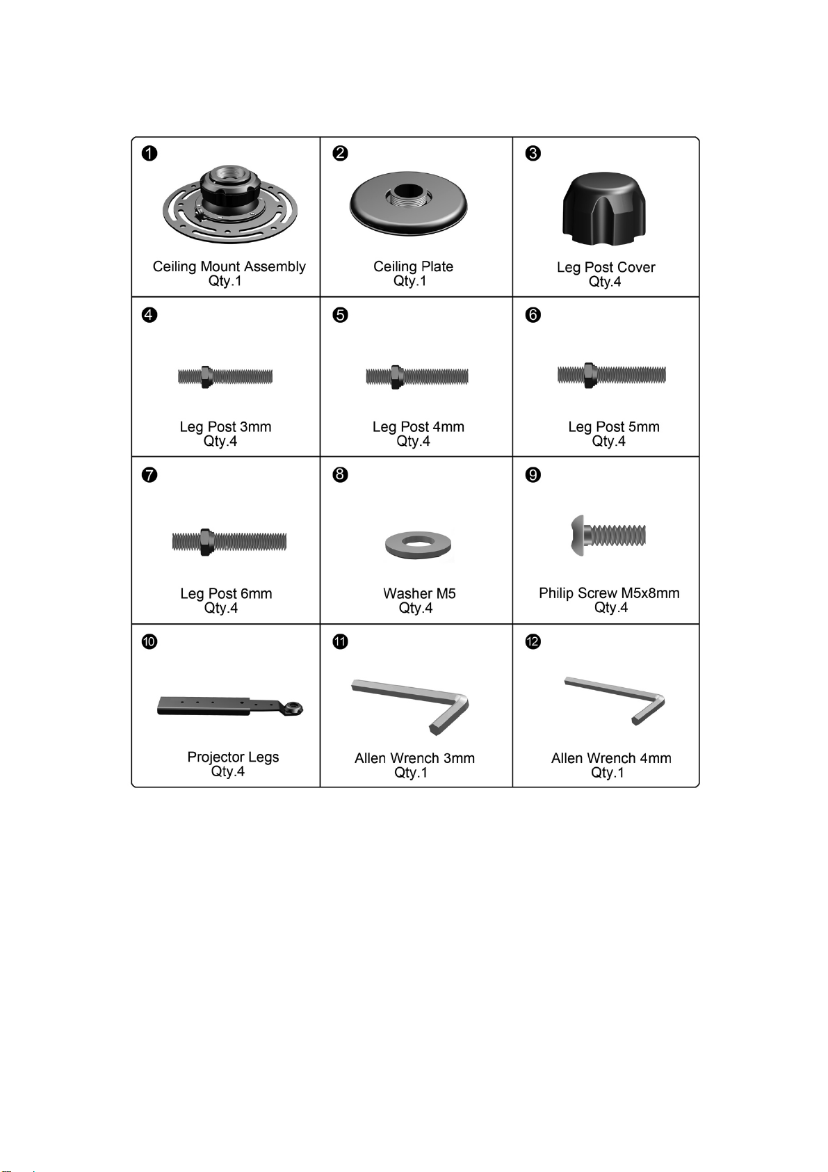
- Verify all parts are included. Do not install if the products or hardware is damage. Not all
hardware included will be used.
- Please contact a qualified installer
- This product contain moving parts, Use with caution
- This product contains small item, keep these items away from children
- Do not exceed the maximum weight capacity for this product
Specification
Maximum Weight Capacity
44(LBS) / 20(KG)

Page
3
Product Dimensions
Tools required for installation

Page
4
Supplied Parts
ASSEMBLY and INSTALLATION
INSPECT THE MOUNT COMPONENTS BEFORE ASSEMBLY
1. Carefully inspect/verify that all components are present.
2. If the mount/components are damaged or missing, please contact the company/seller
of the product you purchased and report the issue.
NOTE: Read all assembly instructions before starting the installation process.

Page
5
Step【1】 Installing the Ceiling Plate
Drilling into electrical wires can cause death or serious personal injury! Always make
certain area behind mounting area is free of electrical wires before drilling or installing.
Improper installation can lead to projector mount falling causing severe personal injury or
damage to equipment. It is installer’s responsibility to make sure the combined weight of all
components does not exceed weight capacity of 44lbs (20Kg).
Do not install near air conditioner vents where there is excessive dust or smoke.
Note: To determine require mounting location; ensure that knowing the projector lens
distance to screen distance. Please see projector details specifications on
determining the distance.
Wood Ceiling Installation
1. Disassemble the Ceiling Plate Cover from Ceiling Plate (2) as shown. (See Figure 1-1)
2. Place the Ceiling Plate to wood ceiling at desired location, mark location with pencil.
3. Drill wood ceiling pilot hole of 7/32” (5mm), pilot drill depth of 3”(75mm) and ensure pilot
hole are straight.
4. Insert Lag Bolt through Washer, Ceiling Plate and install into pilot hole. Repeat for
remaining Lag Bolts. Select hardware that fits your application (See Figure 1-2).
Tighten the Lag Bolt so the Ceiling Plate is secured to the wood ceiling. Do not over
tighten the Lag Bolt.
Plaster Ceiling Pilot
Pilot Hole Size
Pilot Drill Depth
7/32"
3 "
5mm
75mm
Figure 1-1

Page
6
5. Then, proceed to place the Ceiling Plate Cover onto the Mounted Ceiling Plate and press
firmly on the cover to make sure it is in place. (See Figure 1-3)
Figure 1-2
Figure 1-3

Page
7
Step【1】 Installing the Ceiling Plate
Drilling into electrical wires can cause death or serious personal injury! Always make
certain area behind mounting area is free of electrical wires before drilling or installing.
Improper installation can lead to projector mount falling causing severe personal injury or
damage to equipment. It is installer’s responsibility to make sure the combined weight of all
components does not exceed weight capacity of 44lbs (20Kg).
Do not install near air conditioner vents where there is excessive dust or smoke.
Note: To determine require mounting location; ensure that knowing the projector lens
distance to screen distance. Please see projector details specifications on
determining the distance
Masonry Installation
1. Disassemble the Ceiling Plate Cover from Ceiling Plate (2) as shown. (See Figure 1-4)
2. Attach the Ceiling Plate to masonry ceiling, mark the mounting location. Drill the masonry
pilot hole of 3/8”(10mm), pilot drill depth of 3”(75mm) and ensure the pilot hole are straight
and completely through the structural. Insert anchor into anchor hole and seat with gentle
tapping from hammer. Anchor should be fully engaged into structural. Repeat for
remaining anchor.
3. Insert Lag Bolt through Washer, Ceiling Plate (2) and install into pilot hole. Repeat for
remaining Lag Bolts. Select hardware that fits your application (See Figure 1-5).
Tighten the Lag Bolt so the Ceiling Plate is secured to the masonry ceiling. Do not
over tighten the Lag Bolt.
Figure 1-4

Page
8
Masonry Pilot
Pilot Hole Size
Pilot Drill Depth
3/8"
3 "
10mm
75mm
4. Then, proceed to place the Ceiling Plate Cover onto the Mounted Ceiling Plate and press
firmly on the cover to make sure it is in place. (See Figure 1-6)
Figure 1-5
Figure 1-6

Page
9
Step 【2】 Attaching the Ceiling Mount Assembly to Ceiling Plate
1. Remove the Projector Plate from the Ceiling Mount Assembly (1) as shown (See Figure
2-1)
2. Connect the Ceiling Mount Assembly Head to the Ceiling Plate. Secure the Ceiling Mount
Assembly Head by turning the Ceiling Mount Assembly head in clockwise until tight. (See
figure 2-2).
3. Tighten set screw using Allen Wrench 3mm (11)supplied. (See Figure 2-3)
Figure 2-2
Figure 2-3
Figure 2-1

Page
10
Step 【3】 Finding Centre Gravity of the Projector
1. Pick up the projector using both of your index fingers. Move your fingers along the side of
the projector until you find it is level. Repeat for perpendicular side on this process, where
both balance point’s meet is the center gravity of your projector. Use a pencil to mark on
this point. (See Figure 3-1)
Figure 3-1

Page
11
Step 【4】Attaching Projector Plate to the Projector
1. Determine the diameter of the Leg Posts (4, 5, 6, or 7) your projector requires by hand
threading them to the Projector. (See Figure 4-1)
2. Before you assembly the Projector Legs (10), ensure that the Leg Post must be firmly
attached into Projector. Then, proceed to thread the Projector Legs(10)onto Leg Post as
shown. (See Figure 4-2)
3.To make Projector Leg adjustments, loosen the screw with supplied Allen Wrench 4mm
(12)and adjust to your desired position. Re-tighten the screw firmly. (See Figure 4-3)
Figure 4-1
Figure 4-2
Figure 4-3

Page
12
Figure 4-5
4. Place the Projector Plate over the Projector Legs (10) and align the mounting holes as
shown. Tighten Hex Screw M5x8mm using Allen Wrench 4mm supplied.(See Figure 4-4)
5. Once this is done, thread the Leg Post Cover (3)over Leg Post Assembly. (See Figure
4-5)
6. Connect the projector mount assembly to ceiling plate as shown. (See Figure 4-6) by
insert the pin on the projector plate into the slot in the Ceiling Mount Assembly Head to
lock the projector mount assembly.
Figure 4-4
Figure 4-6

Page
13
7. Adjust and align the locking plate connector as shown. (See Figure 4-7)
8. Make sure locking plate connector holes are match up and aligned. Proceed to tighten the
Ceiling Mount Assembly with Hex Screw M5x8mm using Allen Wrench 4mm (12) supplied.
(See Figure 4-8)
Figure 4-8
Figure 4-7

Page
14
Step 【5】Adjusting the position of the Projector
1. This product is designed to adjust quickly and easily according to your needs.
2. Side ways pitch and the pitch angle up to 20 degrees. (See Figure 5-1)
2. To make rotate adjustment, ensure that the weight of the projector is supported. The
product can reach 360 degrees rotation. (See Figure 5-2)
Figure 5-1
Figure 5-2

Page
15
DYCONN PRODUCT WARRANTY
To obtain warranty service, contact Dyconn customer service at (855) 239-2666 or visit
www.dyconn.com. Dyconn disclaims any liability for modification, improper installations,
or installations over specified weight range. Dyconn will not be liable for any damages
arising out of the use or inability to use Dyconn products. Warranty specification is subject
to change without prior notice.
Table of contents
Popular Projector Accessories manuals by other brands

Panasonic
Panasonic ET-LAC100 operating instructions

Canon
Canon LV S3 - SVGA LCD Projector Assembly & installation manual

NEC
NEC NP02WK Installation and adjustment manual

AVstumpfl
AVstumpfl T32-SHIFT instructions

New Star
New Star BEAMER-C80 instruction manual

New Star
New Star Neomounts BEAMER-C80WHITE instruction manual

Speaka Professional
Speaka Professional SP-WTR-400 operating instructions

Sharp
Sharp AN-W9Z manual

Premier Mounts
Premier Mounts Low-Profile Dedicated Projector Mount... installation instructions

EPV
EPV EDGE FREE AcousticPro 4K eFinity Series user guide

Sony
Sony HCS-W80 instructions

BenQ
BenQ InstaShow X user manual