dye RIZE CZR Series User manual

DYEPA I N T B A L L . C O M
OWNER’S MANUAL

01
TA B L E O F C O N T E N T S
- IMPORTANT SAFETY INSTRUCTIONS AND GUIDELINES . . . . . . . . . . . . . . . . . . . . . . . . PAGE 0 2
- QUICK START UP GUIDE . . . . . . . . . . . . . . . . . . . . . . . . . . . . . . . . . . . . . . . . . . . . . . . . . . . PAGE 0 4
- RIZE
RIZE
RIZE
™ BOA RD SETTINGS AND F UNCTIONS . . . . . . . . . . . . . . . . . . . . . . . . . . . . . . . . . . . PAGE 0 6
- TRIGGER ADJUSTMENTS . . . . . . . . . . . . . . . . . . . . . . . . . . . . . . . . . . . . . . . . . . . . . . . . . . . PAGE 13
- ™ BOLT ASSEMBLY A ND MAINTENANCE . . . . . . . . . . . . . . . . . . . . . . . . . . . . . . . . . PAGE 14
- ™ BOLT O-RING LIST . . . . . . . . . . . . . . . . . . . . . . . . . . . . . . . . . . . . . . . . . . . . . . . . . . . PAGE 17
- F EED NECK ADJUSTMENT . . . . . . . . . . . . . . . . . . . . . . . . . . . . . . . . . . . . . . . . . . . . . . . . . . PAGE 18
- HYPER3™ REGULATOR ADJUSTMENT AND MA INTENANCE . . . . . . . . . . . . . . . . . . . . . . PAGE 20
- VELOCITY ADJUSTMENT . . . . . . . . . . . . . . . . . . . . . . . . . . . . . . . . . . . . . . . . . . . . . . . . . . . PAGE 20
- ANTI C HO P EYES AND BA LL DETENTS . . . . . . . . . . . . . . . . . . . . . . . . . . . . . . . . . . . . . . . PAGE 22
- . . . . . . . . . . . . . . . . . . . . . . . . . . . . . . . . . . . . . . . . . . . PAGE 2 4
- TROUBLE SHOOTING . . . . . . . . . . . . . . . . . . . . . . . . . . . . . . . . . . . . . . . . . . . . . . . . . . . . . . PAGE 25
- EXPLODED VIEW . . . . . . . . . . . . . . . . . . . . . . . . . . . . . . . . . . . . . . . . . . . . . . . . . . . . . . . . . PAGE 2 8
- WARRANTY AND LEGA L INF ORMATIO N . . . . . . . . . . . . . . . . . . . . . . . . . . . . . . . . . . . . . . PAGE 2 9
W W W . D Y E P A I N T B A L L . C O M
RIZE CZR™ OWNER’S MANUAL
INC LUDED W ITH YO UR R IZE CZR ™
RIZE CZR™ Marker
A llen tool set including 0 .0 5”, 1/ 16”, 5/ 64 ”,
3/ 32”, 1/ 8”, 5/ 32”, 3/ 16” and 1/ 4”.
1/ 4 oz . DY E Slick Lube™
Parts K it
Barrel Plug
Quick Start Guide
Warranty Card
9V Battery
The RIZE CZR™ comes with the tools req uired to p erform
general maintenance and setting up.
For a comp lete service the following to ols are req uired
C- clip p liers
# 0 Phillips head screw d river
A sharp p ick to remove O- rings
14“ 2pc Proto Barrel
ON / OFF AIRPORT AD JUSTMENTS

W W W . D Y E P A I N T B A L L . C O MWWW . D Y E P A I N T B A L L . C O M
• Compressed gas is dangerous, d o not allow compressed gas to
come in contact with your skin or try to stop a leak by covering it
with your hand.
• Always fit a b arrel b locking device to your ™ when not in use on
the field of play.
• The owner’s manual and any related warning s or instructions should
always accompany the product for reference or in the event of resale
and new ownership.
• Do not point the ™ marker at anything that you do not intend to
shoot.
• Do not shoot at people, animals, houses, cars or anything not related
to the sport of paintb all.
• Do not fire the ™ without the bolt screwed in completely.
• If you read these instructions and do not fully understand them or are
unsure of your ability to make necessary adjustments prop erly,
call DYE Precision or your local pro shop for help.
• The RIZE
RIZE
RIZE
RIZE
RIZE
RIZE
RIZE
RIZE
RIZE
RIZE
™ marker is not a toy. Misuse may cause serious injury or death.
• Please read , understand and follow the directions in the ™
owner’s manual.
• Eye p rotection that is designed specifically for paintball and meets
ASTM/ CE stand ards must be worn by user and persons within rang e.
• Recommend 18 years or older to p urchase. Person under 18 must
have adult sup ervision.
• Always treat the ™ marker as if it were loaded and able to fire.
• Do not exceed 850 psi input pressure.
• Only use .68 caliber paintballs that meet ASTM/CE standard s.
• Ensure all air lines and fittings are tig htened and secured before
gassing up the ™.
• Always chronograph the ™ marker before playing paintb all.
• Never shoot the ™ marker at velocities in excess of 30 0 feet
per second , or at velocities greater than local or national laws allow.
• Never look into the barrel or breech area of the ™ when the
marker is switched on and able to fire.
02 03
W A R NIN G
IMPORTANT SAFETY INSTRUCTIONS AND GUIDELINES
W A RNIN G
IMPORTANT SAFETY INSTRUCTIONS AND GUIDELINES

04 05
W W W . D Y E P A I N T B A L L . C O M W W W . D Y E P A I N T B A L L . C O M
QUICK START UP GUIDE
Before playing with your new RIZE ™ paintball marker there are a few
important steps to take.
STEP 1. BATTERY INSTALLATION
A . Remove three right hand sid e grip p anel screws with a 3/ 32” allen key.
B. Open grip panel and install 9V battery into the connector inside the frame. Start
by inserting the top of the battery into the recess and aligning the battery terminals
with the contacts on the board, then pushing the bottom of the battery fully into
place. Ensure that the battery removal ribbon leaves a small tail accessible from
under battery when installed to aid for easy battery removal. Note the markings
above the battery housing which indicate which of the board contacts are positive
and negative and install the battery accordingly.
C. Close g rip p anel and tig hten the three screws back. W hile closing the p anel
ob serve that no wires g et caug ht b etween the frame and the g rip p anel.
STEP 2. BARREL INSTALLATION
A . Screw on the b arrel to the front of the RIZE ™. Make sure it thread s all the
way in and is secure.
B. Attach the b arrel p lug so that it covers the tip o f the b arrel and secure
the g un.
STEP 4 . ATTACHING GAS SOURCE
Screw on a preset air system into the airp ort located on the b ottom of the grip frame.
Be sure the air system is screwed in all the way into the A irp ort. If there is a leak
from the airport when screwing in the air system, replace the o- ring on the p reset reg ulator.
STEP 5. TURNING ON THE RAIL™ AND CHECKING THE VELOCITY
A . Make sure yo u and everyb ody around you is wearing A STM / CE ap p roved
paintb all masks.
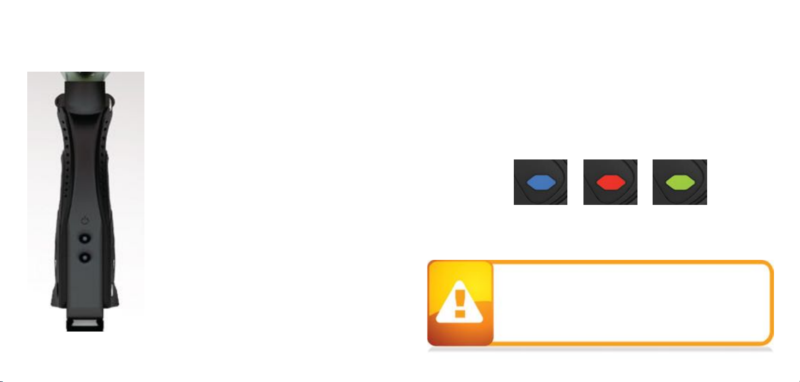
B. Press and hold the top b utton located b ehind the grip frame until the RA IL™
turns on. WARNING, THE RAIL™ IS LIVE. MAKE SURE BARREL PLUG IS IN PLACE
AND DO NOT POINT THE RAIL™ AT ANYTHING YOU DON’T INTEND TO SHOOT.
C. F ill up the loader with .68 calib er paintb alls.
D. Shoot the RA IL™ over a chronograp h to check the velocity. If ad justment is
need ed , adjust the velocity b y turning the Hyper3™ velocity ad justment screw with
a 3/ 16” allen key. In ( clockwise) will red uce the velo city and out ( co unter clockwise)
will increase the velo city. A fter each ad justment it takes a few shots befo re the
change can b e seen on the chronog rap h. Never adjust the RA IL™ to shoo t faster
than 30 0 fps or what the field rules / local laws p ermit.
Q UIC K REF ERENC E
USI NG YO UR MAR KER
Q UIC K REF ERENC E
USI NG YO UR MAR KER
STEP 3. LOADER INSTALLATION
When screwing the air system into the airport, always check that the threads on
the air system and the airport are clean and not worn out. If you think the thread s
are not in g ood condition, contact DY E Precision o r a p rofessional store b efore
screwing in the air system.
The RIZE ™ airp o rt will work with bo th 30 0 0 psi, 450 0 p si air systems and CO2
tanks fitted with an anti - sip hon.
With the clamp lever lifted away from the feed neck press your hopper into the feed
neck collar. Then lower the lever down to secure the loader. If the collar’s grip needs
to be adjusted turn the upper screw with a 3/32” hex tool. If the grip is too tight turn
the screw counter- clockwise. If the grip is not tight enough turn the screw clockwise. For
best results use a force feeding motorized loader, preferably a DYE Rotor Loader.

06 07
RIZE CZR ™B OA RD
SE TTI NGS A ND F UNC TIONS
RIZE CZR ™B OA RD
SE TTI NGS A ND F UNC TIONS
TURNING THE RIZE CZR™ ON AND OFF
To turn on the RIZE CZR
RIZE
RIZE CZR
RIZE CZR
RIZE CZR
RIZE CZR
™, press and hold the p ower b utton
until the LED’s turn b lue. The blue lig ht ind icates board b oot up.
After the b oot up seq uence, the LED’s will turn either RED
( no ball) or GREEN ( ball in b reach, read y to fire) . To turn the
™ o ff, press and ho ld the power button until the LED’s
turn off.
NOTE: The RIZE CZR
RIZE CZR
™ automatically switches off after 10
minutes of non-use.
FIRING THE ™
A s so on as the marker is turned on and the LED’s turn from
blue to either red or g reen, the ™ is read y to fire. If there
is no b all and the LED’s are RED, you need to ho ld the
trig g er fo r 1 second to force the ™ to fire o nce. If there is
a p aintb all insid e the b reech and the LED is green, just p ress
the trigg er to fire the marker.
LED LIGHT INDICATOR
The ™ uses a super brig ht LED mounted on the circuit
board inside the g rip frame. This light is used to provid e
information to the user about the ™. It is mounted b ehind
the PROTO™ log o on the left side of the grip p anel.
When you turn on the marker in normal operation mode with the power b utton, the light colors
mean the following :
Blue -Bo ot sequence
Red -Breech is clear, no ball d etected insid e the ™ ( eye is on)
Green -Ball in b reech, ready to fire ( eye on)
Blinking Red -Eye is turned off
Blinking Green -Eye failure, eye is b locked or d irty ( see ™ Eye, pag e 26)
To turn off the eye feature press and hold the b ottom b utton until the LED lig ht starts b linking
Red ind icating the eye feature is turned off.
NOTE: The eye is always activated when you turn the marker on.
When servicing your marker:
• Make sure a b arrel p lug is fitted to the ™.
• Make sure your hopp er is removed fro m the ™.
• Make sure there are no p aintb alls in the b reech o f the ™.
• A lways remove the first stage reg ulato r and relieve all resid ual g as
pressure from the ™ before disassemb ly.
• The ™
can hold a small resid ual charge of g as, typ ically 2 shots, with
the first stag e reg ulato r removed . A lways d ischarg e the marker in a safe
direction to relieve this resid ual gas p ressure.
RIZE CZR
RIZE CZR
RIZE CZR
RIZE CZR
RIZE CZR
RIZE
RIZE
W W W . D Y E P A I N T B A L L . C O M W W W . D Y E P A I N T B A L L . C O M

08 09
W W W . D Y E P A I N T B A L L . C O M W W W . D Y E P A I N T B A L L . C O M
RIZE CZR™BOARD
SE TTI NGS A ND F UNC TIONS
BOARD SETTINGS AND CONFIGURATION MODE
There are five settings yo u can alter on the RIZE ™ bo ard with
the DIP switches inside the g rip frame ( see fig ure 1) :
ABS A nti Bolt Stick.
Trigger Sensitivity This setting ad justs the d elay
between two trig g er pulls.
Dwell This is the time the soleno id is
activated for.
Rate Of F ire This setting is for ad justing the
maximum rate of fire
Firing Mode This is the firing mod e the RIZE ™ uses.
There are two DIP switches mounted on the b oard of the RIZE ™ ( See fig ure 1) . The first o ne is
used for the A BS setting and the second o ne is used to access a configuratio n mod e which
changes the other fo ur setting s.
Anti Bolt Stick - W hen A BS is activated, the d well is increased after
15 second s of non- use for the next shot fired. This help s to p revent
bo lt- stick, but may result in hig her velocity for the first sho t.
FIGURE 1
ABS ON
(DEFAULT)
ABS OF F
CONF IGURATION MODE - The following setting s can only b e
modified in config uration mod e. To activate the config uration
mode, turn your marker off and set DIP switch 2 to the ON
po sition. Next, turn your marker on. The LED's cycle throug h
all colo rs for one second to indicate that you have entered
the config uration mode.
To cycle thro ug h different setting s, pull and release the trigger.
Config uration mode has 4 setting s that can b e changed.
TO CHANGE A VALUE OF A SETTING
1. W hile in the config uration mod e, choose the setting you wish to change by p ulling the trig g er
to cycle throug h d ifferent op tions.
2. When the LED ind icates the color of the setting you wish to chang e, pull and ho ld the trig g er
until the LED starts to flash.
3. The LED will flash as many times as the previo us setting was and it will then turn off. Now p ull
the trigg er as many times as you wish the new setting to b e. No te: You must enter a value at this
po int, if yo u d o not wish to alter the setting then re- enter the p revio us value.
4. When d one, the LED will cycle thro ug h all the colo rs ag ain to ind icate setting was saved and
turn b ack to g reen. You can now chang e another setting or q uit the configuratio n mod e.
5. To exit config uration mod e, set DIP 2 to the off p o sition.
NORMAL
MODE
CONFIGURATION
MODE
RIZE CZR™BOARD
SE TTI NGS A ND F UNC TIONS
• The RIZE ™ is not water resistant. Excess moisture can cause damage
to electronic parts.
• Keep the board and all electrical components clean of dirt, paint and moisture.
• To clean the board, use canned air. If a more aggressive cleaning method
is needed, lightly scrub the components with a soft, dry brush.
Heavy scrubbing will damage the board.

10 11
W W W . D Y E P A I N T B A L L . C O M W W W . D Y E P A I N T B A L L . C O M
RIZE CZR™BOARD
SE TTI NGS A ND F UNC TIONS
BLUE - Rate Of Fire ( ROF) Values 1 - 30
The ROF setting is used to set the maximum rate of fire o f the RIZE™.
The values d o no t corresp ond directly to a certain Balls Per Second
( BPS) value. You will need to use the tab le b elow to lo cate yo ur
desired maximum ROF setting.
The factory setting is 3(10 .0 bps).
Increasing ROF too high will increase probability of ball breakage.
If this occurs decrease ROF setting.
YELLOW - Firing Mode Values 1 - 4 (default 1)
This setting chang es the firing mo de of the RIZE ™. Default is
semiauto matic. In the semiautomatic mod e, one trig ger p ull
shoots o ut one p aintb all. The PSP mode and the Millennium
mode follow the rules of the paintb all to urnament series.
Value 1 - Semi- automatic Mod e
Value 2 - Millennium Mod e
Value 3 - PSP Mod e
Value 4 - F ull auto with first shot safety feature
RIZE CZR™BOARD
SE TTI NGS A ND F UNC TIONS
GREEN - Trigger Sensitivity Values 1 - 20 ( factory default 5)
Trigger sensitivity is the amount of time that the trigger has to be
released before the next trigger pull is allowed. In some situations
with too low of a value, the RIZE™ can register more trigger pulls
than what was actually pulled. This can cause the RIZE™ to shoot full
auto, even in semi-automatic mode. To fix this, adjust the trigger
sensitivity setting higher.
RED - Dwell Values 1 - 50 ( factory default 40 )
Dwell is the amount of time that the solenoid will be activated.
Follow these steps for the best way to set your dwell:
• Remove loader and any paintballs from the RIZE™ marker.
• With the dwell set at 20, start increasing the value until the marker
begins to fire.
• When you reach the setting where the marker begins to fire, get
some paint and a loader and go to a chronograph.
• Increase the dwell until you see no increase in the velocity.
This is the optimal dwell setting to be used.
NOTE: You cannot turn your marker off with the power button
when the marker is in configuration mode. You must first set DIP
switch 2 to the OFF position.
TRIGGER
PULLS
TRIGGER
PULLS
TRIGGER
PULLS
TRIGGER
PULLS
TRIGGER
PULLS
1
2
3
4
5
6
BPS BPS BPS BPS BPS

12 13
W W W . D Y E P A I N T B A L L . C O M W W W . D Y E P A I N T B A L L . C O M
TR I GGE R
ADJUSTMENT
RIZE CZR™B OA R D
SE TTI NGS A ND F UNC TIONS
BATTERY
The 9V battery will last for about 12,0 0 0 shots. Please b e aware that there are sub stantial
differences in p erformance b etween d ifferent b rand s of batteries. Use of high quality alkaline or
lithium io n b atteries is recommended fo r maximum battery life. If you p lan not to use yo ur marker
for a long p erio d of time ( a month) , it is recommend ed that you remove the b attery from the
marker. W hen the b attery voltag e starts to g o too low, the marker will not fire with every trig g er
pull. For tournament use, it is recommend ed to chang e the battery fo r each tournament.
CHANGING THE BATTERY
The b attery is housed on the rig ht sid e o f the grip frame. To access the b attery, remove the three
screws ho lding the rig ht sid e g rip p anel d own. Use a 3⁄32” allen key. When inserting a new b attery
notice the + and - marks on the board. The positive lead of the 9V battery g oes to the left and the
negative lead to the rig ht.
NOTE: If the marker will not function with the eye on, there is a good chance the battery needs
to be changed.
• A low battery will not b e able to p ower both the ACE eye and the trigg er
switch, causing ACE eye failure.
• If the b attery is low, the marker will not fire with every trig g er pull.
• Be sure the trigg er is not adjusted to the p oint where it is too sensitive
and may cause accidental d ischarg e of the marker.
• Removing the trigger spring will cause premature wear on the microswitch,
resulting in failure.
•Be sure you do not pinch the wires between the frame and body when
reattaching the frame to the body.
ADJUSTING YOUR TRIGGER
The Trig g er’s forward travel and over travel are fully
adjustab le so that the user can fine- tune the trigger to
his/ her exact p reference.
To adjust the trigg er an .0 50 ” and 5/ 64 ’ A llen key is
need ed . There are two ad justment screws located o n the
trig g er.
The up p er screw on the fro nt of the trig ger controls the
forward travel (1) and req uires a 5/ 6 4 ” allen wrench to
adjust. Screwing it in will incease the trigger ’s leng th of p ull.
Note: If this screw is screwed too far out, the switch
will be depressed all the time causing the RIZE ™ to fire
once immediately after turning it on and not firing after that! (Fig. 1).
The lower screw on the front o f the trig g er contro ls the over travel ( 2) and req uires the .0 50 ” allen
wrench to ad just. By turning this screw you can adjust how far b ack the trig g er will travel.
Note: If this screw is adjusted too far, the trigger will not be allowed to travel far enough to
depress the switch and the marker will not fire.
The trigger sp ring used to return the trig g er is lo cated insid e the frame. It is not sug g ested to
remove this sp ring as it will cause excess wear on the microswitch and cause trig g er b o unce.
1
2
FIGURE 1

14 15
W W W . D Y E P A I N T B A L L . C O M W W W . D Y E P A I N T B A L L . C O M
The RIZE RIZE
RIZE
RIZE
RIZE
RIZE
RIZE RIZE
RIZE
RIZE
RIZE
RIZE
™ BOLT is the main comp onent o f the ™ marker. In ord er to achieve the best
possible p erformance of the RA IL™ it is essential that the ™ BOLT is kept clean, well lubed
and in g ood working order.
The ™ BOLT should be cleaned and re- lubed after each d ay of use.
There are 4 p arts in the ™ BOLT kit that mount tog ether as one unit. To remove the ™
BOLT from your ™, use a 1/ 4 " allen key and turn the Back Cap out 2 full turns counter
clockwise. Now p ull out the complete RA IL™ b olt kit from the ™.
To d is- assemble the ™ BOLT kit you unthread the front most part called the Can and the
Manifold from each o ther. Then pull out the actual moving b olt from inside these p ieces. Notice
that to separate the Can and the Bolt you need to remove
the b olt tip O- ring before the b olt is ab le to slid e throug h
the Can.
HOW DOES IT WORK
A ir is sup p lied into two p oints on the ™ BOLT. In the
back air is routed thro ug h the Back Cap and Manifold
and fills up the supp ly chamber around the Manifold. In
the front air is routed throug h the solenoid into the Can.
This air p ushes ag ainst the Sail on the Bolt, which keep s
the b olt in the back p osition.
F ORWARD P OSITION
RIZE CZR™B O LT
A SSE MB LY A ND MA INT E NA NC E
RIZE CZR™B O LT
A SSE MB LY A ND MA INT E NA NC E
When the ™ is fired the solenoid is actuated
and the air insid e the Can is exhausted o ut. The
force created by the air insid e the sup ply chamb er
causes the b olt to start moving forward. Once the
bolt has moved ab out half way forward , the tail of
the b olt closes the inp ut into the sup ply chamb er.
Once the Bolt reaches the forward point, the valve
of the ™ Bolt is o pened and air insid e the
supply chamber go es throug h the Bolt and fires
the p aintb all. After this the solenoid is d e-
activated and g as is sup plied through the
solenoid b ack into the Can. This causes the Bolt
to return to the b ack p osition and the sup p ly
chamb er to b e re- charg ed .
When servicing your marker:
• Make sure your hop p er is removed from the marker.
• Make sure there are no p aintb alls in the b reech o f the marker.
• A lways remove the air sup p ly and relieve all g as p ressure in the marker
before d isassembly.
• When using the marker in temp eratures b elow 50 ° Fahrenheit it may be
necessary to lub e the RA IL™ b olt mo re freq uently.
BACK P OSITION

16 17
W W W . D Y E P A I N T B A L L . C O M W W W . D Y E P A I N T B A L L . C O M
RIZE CZR™B O LT
A SSE MB LY A ND MA INT E NA NC E
67
1 1 1
4
1
2
1
4
10 20 N 70
20 17 N 70
30 15 N 70
40 14 N 70
5
6
7
009 N 70
0 13 x2mm N 9 0
RAIL™ BOLT O-RING LIST
RIZE CZR™B O LT
A SSE MB LY A ND MA INT E NA NC E
009
3
MAINTENANCE
If the RIZE CZR™
BOLT is not kept clean
and well lubed, you will either start
seeing erratic velocity, leaks or over
long period of time, physical
damage to the RIZE CZR™ BOLT
components.
For troubleshooting leaks and other bolt problems, consult the
troubleshooting section at the end of this manual.
55
Bolt Front Bumper
The basic maintenance for the RIZE CZR™ BOLT is to clean all surfaces of
dirt, broken paint or other debris, check for any wear and tear on
the O-rings and changing them if needed, and finally applying
a thin coat of DYE Slick Lube on all surfaces. Before installing
the RIZE CZR™ BOLT back to the RIZE CZR™ marker check
that the bolt moves freely without a lot of friction and
make sure all pieces are threaded
together snugly!.

18 19
W W W . D Y E P A I N T B A L L . C O M
LOA D E R S A ND F E E D NE C K A I R / NI TR O GE N
AIR / NITRO GEN TA NK OPTIONS AND INSTALLATION
The RIZE CZR™ with Comp ressed air and Nitro gen air
systems such as the DY E Throttle® air system and will also
work with CO2. Do not use any o ther co mp ressed
gas. The o utp ut p ressure from the air system has
to b e between 4 0 0 – 850 psi. If you are using CO2
it is essential that the tank is fitted with an anti-
siphon tub e to p revent liq uid CO2from
entering the RIZE CZR™.
To install an air system, screw the tank into
the airport all the way as far as it will g o.
To remove the air system screw out.
There will be g as leaking for a few
second s while you screw the air system
out. Notice that even with the air
system removed there can be g as
insid e the RIZE CZR™ and it can still
fire
a p aintb all. A lways treat the
marker as being live and never
po int it to anything you d o n’t
intend to shoo t at!
LOADERS AND FEED NECK
To achieve the maximum performance of the RIZE CZR™
you will need to use a motorized loader that force
feeds paintballs into the RIZE CZR™ marker, preferably the
Rotor™ Loader. Using a slower motorized loader or
a non-motorized loader will work, but the rate of fire
and performance will be reduced.
CAM LEVER FEED NEC K
The Cam Lever Feedneck is adjustable to fit any
standard loader.
To fit a loader onto the RIZE CZR™, fit your loader into
the adjustable feedneck and tighten Cam Level into
postion, flush with the feedneck collar.
Loader should now be held in with a snug fit. If not, see below to adjust the Cam Lever tension.
To loosen the locking system and remove the loader, lift the cam lever away from the feed collar.
Take care not to over-tighten the cam locking system. The lever should not be overly difficult to
lower into the locked position.
There is no maintenance needed for the feed neck besides keeping it clean of broken paint, dirt
and debris.
W W W . D Y E P A I N T B A L L . C O M
To adjust the cam locking feed neck, lift the lever away from the feed collar. Using a 5/32" hex
wrench, turn the screw connected to the lever clockwise to tighten or counterclockwise to
loosen the grip on the loader. Once the desired adjustment has been made press the cam lever
down against the feed collar to secure the loader in the feed neck.

20 21
W W W . D Y E P A I N T B A L L . C O M W W W . D Y E P A I N T B A L L . C O M
HY P E R 3 ™ I N- L I NE R E GUL ATO R
A DJUST ME NTS A ND MA INT ENA NC E
HYPER3™ REGULATOR DIS-ASSEMBLY INSTRUCTIONS
Before p erfo rming maintenance on the Hyp er3™ reg ulator, ensure that the RIZE CZR™ is comp letely
deg assed and then unscrew the Hy p er3™ from the RIZE CZR™ marker.
To disassemb le the Hyp er3™ reg ulator you will need a C- clip too l or a strong pick. Remove the C-
clip fro m the b ottom o f the Hy p er 3 reg. Next, unscrew the Brass seat housing from the b ody
with a 3⁄16” A llen key.
To chang e the seat, p ull out the old seat from the housing with a sharp o b ject. Insert the new seat
in p lace and p ush it d own with a flat object. Notice that it takes ab o ut 20 0 0 sho ts for the seat to
perfectly sit into the seat housing . This is called the b reak in p erio d for the reg ulator. Rememb er
to ap p ly lub e to the 010 on the b rass reg seat ho using b efore re- assemb ly. F urther d isassembly to
serv ice the to p section of the Hyp er3™ should b e performed by a trained Tech.
C- CLIP
SEAT HO USING BODY
0 14 BN0 70
REGULATOR SEAT
TOP CA P
VELO C ITY ADJUSTMENT
The velo city of the RIZE CZR™ is ad justed by adjusting the inp ut
pressure into the RIZE CZR™. This is co ntrolled with the Hyp er3™
reg ulator. The Hy p er3™ on the RIZE CZR™ is factory set to 145 psi which
will g ive you a velocity of ab out 285 FPS ( Feet p er Second) .
A 3 ⁄16” allen key will b e need ed for this op eration. Turning the
adjustment screw in ( clockwise) will d ecrease the p ressure, and out
( co unterclockwise) will increase the p ressure. To ad just the
velocity :
1. Make sure you and everybo d y around you is wearing A STM/ CE
approved p aintb all gog g les.
2. Shoot the RIZE CZR ™ over a p aintb all chronog rap h.
3. To lower the velocity turn the Hyp er3™ ad justment screw in. To
increase the velocity turn the screw o ut. Only turn the screw a
quarter turn at a time and shoot over the chronog rap h ag ain.
No tice that a few sho ts are needed b efo re the chang e can be
seen on the chronog raph.
MAINTENANCE
For the RIZE CZR™ to functio n p ro perly, it is essential that the inp ut
pressure into the marker stays consistent at all times. The general
maintenance need ed fo r the Hy p er3™ reg ulator is to keep it clean
of d irt and d eb ris at all times. A more extensive service should b e
performed every 12 mo nths by a trained Tech or if the outp ut
pressure of the reg ulato r b ecomes inco nsistent. This can b e seen
as inco nsistent velo city and verified with a regulator tester ( sold
sep arately ) . Notice that the Hyp er3™ has a b reak in p eriod of
about 20 0 0 shots b efore it achieves the b est p erformance.
HY P E R 3 ™ I N- L I NE R E GUL ATO R
A DJUST ME NTS A ND MA INT ENA NC E

22 23
W W W . D Y E P A I N T B A L L . C O M W W W . D Y E P A I N T B A L L . C O M
A NTI C HO P EY E S/ BA L L DE TE NTS
MA I NTE NA NC E A ND C HA NGI NG
ANTI CHOP EYES
The A nti Chop Eye ( ACE) system will
prevent the RIZE CZR™ from chopping paint
by no t allowing the marker to fire until
a b all is fully seated in front o f the b olt.
The eyes use a b eam across the
breech. On one side there is a
transmitter, and on the op p osite sid e a
receiver. In ord er fo r the marker to fire
with the eyes turned o n, the sig nal
between the two eyes must b e b roken.
After every sho t, before the next ball
drop s in the b reech, the eye
transmitter and receiver must see each
other. If the eyes are d irty and canno t
see each other between shots, the LED
on the b oard will start b linking g reen.
This means that the eyes are d irty. This is an extremely reliab le system as long as the eyes are
kept clean. The most common reason for dirty eyes is broken paint. If the eyes b ecome d irty, the
marker will default to a reduced rate of fire to p revent cho p p ing . If this happens during g ame p lay,
you can by pass this by turning the eyes off. Clean the eyes as soon as possib le.
NOTE: IF THE BATTERY IS LOW, THE MARKER MAY ACT AS IF THE EYES ARE DIRTY OR NOT
FIRE AT ALL. IN THIS CASE, REPLACE THE BATTERY.
SELF CLEANING EYE F EATURE
A NTI C HO P EY E S/ BA L L DE TE NTS
MA I NTE NA NC E A ND C HA NGI NG
If this do es not clear the b lo ckag e use a swab to clean the inside of the b reech.
For a more thorough cleaning , pull the Eye Pip e with the ball detents out the front of the b reech.
With the Eye Pip e out use a swab to clean the b reech. This should b e enoug h to clean the eye
system. If the system need s further cleaning , pull out the eye carrier and eye wires thro ugh the
feed neck. To prevent d amaging the eye wires, it is b est to remove the frame and d isconnect the
eye wires from the b oard. Use a so ft rag and q - tips to clean off any b uilt up p aint or grease.
When re- assembling the eye g uard system, work backward s from d isassemb ly. The Eye Pip e is
keyed into the b reech and can only g o in o ne way.
NOTE: REGULAR EYE CLEANING IS RECOMMENDED EVEN IF NO PAINT IS BROKEN. CLEAN
THE EYES EVERY TWO MONTHS OR 10 ,0 0 0 SHOTS TO ELIMINATE ANY BUILT UP DIRT.
EXCESS GREASE CAN BUILD UP IN FRONT OF THE EYES. REMEMBER TO CHECK F OR THIS
AF TER GREASING THE BOLT AND CYCLING THE MARKER A F EW TIMES.
CHANGING BALL DETENTS
The b all detent system is clipped to the o utsid e of the Eye Pip e. The ball d etent system need s
little or no maintenance. The d etents should easily flex out of the way with little force, such as a
paintb all moving p ast. If you are exp eriencing d ouble feed ing or cho p ping , check the co nd itio n of
your ball detents with your finger to make sure they are not b roken, stuck in the up or d own
po sition, and that they move in and o ut of the b reech freely. If excessive b roken p aint or d irt has
jammed your ball detents, remove the Eye Pip e/ detent system from the fro nt of the RIZE CZR ™ and
unclip the d etents fo r a thoro ug h cleaning . Reinstall the d etents, and Eye Pipe after you have
sufficiently cleaned the d etents and b reech.
Be careful not to over- flex the detents when hand ling them. Excessive flexing co uld b reak or
damag e the d etents.
The RIZE CZR™ is equipped with a self-cleaning eye feature. There is a clear polycarbonate sleeve
mounted inside the breech of the gun covering the eyes. When the bolt tip O-ring passes
through the Eye Pipe, it sweeps off any dirt, grease or paint that could be blocking the
eyes. Normally it is enough to just fire the RIZE CZR™ to clean anything blocking the eyes.

24 25
W W W . D Y E P A I N T B A L L . C O M W W W . D Y E P A I N T B A L L . C O M
AIR LEAKS
e
AIR LEAKING FROM THE HYPER3™ REGULATOR
• First locate the position of the leak.
• For disassembly instructions consult the
technical section under Hyper3™ regulator.
• If the leak is coming from the bottom of the
regulator you will need to disassemble the
regulator and change the # 010 O- ring and
the seat on the brass seat retainer mounted
inside the Hyper3™ regulator.
• If the leak comes from the small hole in the
middle of the regulator there are two possibl
O- rings. Change the # 015 O- ring on the
piston and the # 0 07 urethane O- ring inside
the body of the regulator.
• If the leak is from the top of the regulator
change the #014 O- ring on the outside
of the cap.
• Change the #014O-ring on the top cap of
the Hyper3™ and apply a small amount of lube
to the O- ring.
AIR LEAKING BETW EEN BODY AND F RAME
• A leak between the body and the frame can be
caused by a couple of things.
• First Check that the Hyper3 reg is not set too
high or too low.
• If above doesn’t help, remove the frame from
the RIZE CZR™ and check the hose connections
between the solenoid and the hose fittings.
• Last possibility is that one of the hose fittings
is leaking. Gas up the RIZE CZR™without the frame
attached and try to locate the exact point of
leakage. If the leak is coming from one of the
hose fittings, remove the screw, check and
replace any damaged o-rings and re-attach
screw to the body.
AIR LEAKING FROM BACK OF THE RIZE CZR™
• Check that the bolt kit is tightened all the way
into the ™. If the bolt kit is loose, it will
start to leak.
• If above does not solve the leak, remove the
bolt kit and change the #020 O-ring on the
back cap of the bolt kit. Also change the two
#0 09 O-rings located on the tail of the bolt.
Lube well and re-insert the bolt kit into the
™. Check bolt kit break down picture on
page 19 for O-ring locations
AIR LEAKING FROM F RONT OF THE
RIZE CZR
™
• Remove the Bolt kit from the marker and
change the #017 O- ring located inside of the
Can and the #014 O-ring located inside
the Manifold. Lube well and re-assemble.
• If above doesn’t help, try changing the
TRO UBL E SHOOTING GUID E
RIZE CZR
RIZE CZR
ON/OFF AIRPORT DETAIL
REMOVE PIN-H OUSING ASSEMBLY
To disassemble the UL airport use the airport tool included on the DYE Multi-Tool.
• Insert the airport tool into the Pin Housing and turn counterclockwise. Note
that the airport lever must be in the OFF position. Remove
housing out of the airport body.
• The pin and 005 O-ring may or may not come out with the housing, if necessary use
a pair of needle-nosed pliers to pull the pin out.
INSTALL PIN HOUSING ASSEMBLY
• Coat the 005 O-ring in lube and drop it into the airport body. Use the tip of a 1/4” Allen
wrench to fully seat the O-ring in place by pushing gently on it.
• Insert the Pin into the Pin Housing from the backside.
• Place the housing onto the airport tool and insert the housing into the airport body.
• Turn clockwise until the Pin Housing fits snugly into the airport body.
*If the airport tool is not available, a pair of needle-nose pliers can be used to unscrew the
Pin Housing. Just take care to not scratch or damage the threads or Pin Housing.
REMOVE T HE AIRPORT LEVER
• Remove the DYE sphere jewel located in the middle of the airport lever.
• Use a 1/16” Allen wrench to unscrew the retaining screw and remove the screw and lever.
The airport is held in place by a set screw located in the frame, under the battery.
Use a 3/32” Allen wrench to secure the airport to the frame.
AIR LEA KING FROM T HE BAC K OF AIRPORT
• Check the O-ring on the Air system. If needed
change the O-ring and try again. The O-ring
normally used is #015 but some manufacturers
might use a different size. Consult the manual of
the air system you are using.
AIR LEA KING FROM ON/OFF KNOB OR
BLEED HOLE
• Make sure airport is in full on or off position.
• Check 005 O-ring behind pin housing.
• See page 24 for service details.
NOTE: FOR EXPLODED VIEW OF AIRPORT AND PARTS LIST SEE PAGE 28.

26 27
W W W . D Y E P A I N T B A L L . C O M W W W . D Y E P A I N T B A L L . C O M
• Make sure there is a trigg er sp ring inside
the frame.
ERRATIC VELOCITY/ RIZE CZR™WON’T
FIRE
RIZE CZR™ FIRES BUT BALLS ARE DROPPING OFF
OR NOT EVEN COMING OUT OF THE BARREL
• Make sure the b attery is g ood .
• Raise the dwell to factory level ( 4 0 ) .
• Make sure b olt is well lub ed and moves well.
If there is to o much friction in the Bo lt, it will
cause the RIZE CZR™to shoot d own.
• Make sure air system is screwed in all the way.
FIRST SHOT IS TOO HIGH
• Change the Seat inside the Hyper3™ regulator.
For disassemb ly instructions consult the
technical sectio n.
• Try turning off the A BS feature by turning DIP
# 1 to the off p osition.
VELOCITY IS NOT CONSISTENT
• Make sure the p aintb alls you are using fit the
barrel goo d and are consistent in size.
The stock b arrel with the RIZE CZR™ is .68 8 siz e.
You sho uld be ab le to blow the paintball
throug h the barrel but they sho uld not roll
throug h the barrel on their own.
• Remove the bolt kit and re- lub e it. Chang e any
O- ring s causing a lot of friction. Make sure
# 014 O- ring in b olt tip is in p lace and in
good co nd ition.
TROUBLE SHOOTING GUI DE TROUBLE SHOOTING GUI DE
• Raise the dwell.
• Change the battery.
• Check that the Hyper3™ regulato r is working
correctly and that the p ressure is consistent.
A sep arate regulator testing tool is availab le
for this. If needed, disassemble and chang e
worn out O- ring s in the Hyper3™ regulator.
OTHER CATEGORIES
DOUBLE F EEDING
• If you g et two balls firing at once chang e the
ball d etents by removing the Eye Pip e,
rep lacing the orange detent clip and
reinstalling the Eye Pip e.
BREAKING PAINT
• Make sure you use high q uality paintb alls and
that they are stored accord ing to the
manufacturers instructions.
• Check that #14 O- ring on b olt tip is in p lace
and in g ood condition.
• Make sure your loader is working g ood and
that the rate of fire is not set hig her than the
maximum feed rate of the lo ad er.
• Check that the barrel yo u are using is not too
tig ht fo r the paintb alls you are using .
• Check the condition of the b all detents.
.naC eht fo edistuo detacol sgnir-O 020#
Lub e well b efore re- inserting b olt kit.
PROBLEMS W ITH ELECTRONICS
RIZE CZR
RIZE CZR
™ W ON’T TURN ON
• Make sure b attery is new and well charged .
• Check that battery is making contact with the
board terminals insid e the RIZE CZR™.
• Make sure there is no d irt or d ebris b lo cking
the butto n from b eing pressed .
™ W ILL TURN ON / OFF BY ITSELF OR THE
EYES W ILL TURN ON / OFF BY THEM SELVES
• Both of these p roblems are caused b ecause
the butto n( s) are p ressed all the time.
• Remove board from the frame by removing the
grip panel o n the left hand sid e, disconnecting
the cab les and pulling the b oard out. Carefully
remove the two buttons and clean them well.
• Re- assemble and test. If pro b lems p ersist,
contact authoriz ed serv ice center for b o ard
rep lacement.
EYES W ILL NOT WORK, LED KEEPS
BLINKING GREEN
• First chang e the b attery. The eyes are normally
the first thing to sto p working when a battery
is dying.
• Next try to clean the eyes. See p ag e 22
for d etails on how to remove the Eye Pipe and
To test if the eyes wo rk make sure there
is nothing insid e the b reech and that the b o lt is
in the b ack p osition. Turn on the RIZE CZR™, the
lig ht sho uld be red after the b oot up sequence.
If it is, the eyes are working .
• Check that the eye wire is prop erly connected
to the b oard .
• If nothing ab ove helps contact a store or DYE
Precision for eye rep lacement.
SOLENOID W ILL NOT ACTIVATE / TRIGGER
NOT WORKING
• Check that the trig ger adjustment is not set so
that the micro switch cannot activate.
You sho uld hear a small click when pulling
the trigg er.
• If the RIZE CZR
™ fires once when turned on but not
after that your trigg er is set so that the micro
switch is always activated . Re- ad just the trig ger.
• Change the battery if you are not p ositive
ab out it’s charge.
• Check that the solenoid and cap acitor cab les
are attached to the b oard and to the rig ht
connectors ( solenoid should b e attached to
the connecto r that is colored blue) .
TRIGGER BOUNCE / RIZE CZR™ SHOOTING MORE
THAN ONE BALL PER PULL IN SEMI AUTOMATIC
MODE
• Raise the trig g er sensitivity level in the
configuration mo d e.
• Check that the trigg er is not adjusted too short.
clean the eyes.

1
53
8
7
14
17
16
13
11
18
10
6
12
9
4
2
E XP LO D E D VI E W
1
2
3
4
5
6
7
8
9
10
11
12
13
14
15
16
17
PARTS L IST
WA R RANTY
DYE Precision, Inc. warrants for one year to the initial retail purchaser, from the initial date of
purchase, that the paintball marker and regulator are free from defects in materials and
workmanship, subject to the requirements, disclaimers and limitations of this warranty. Disposable
parts, normal maintenance and standard wear and tear parts such as batteries, O-rings and seals are
not covered under warranty. The solenoid and electronic components on the marker are covered
under warranty for six months. This warranty does not cover scratches, nicks, improper disassembly,
improper re-assembly, misuse, neglect or improper storage. Modification to the product will void the
warranty. The only authorized lubricant for the marker is Slick Lube™. Use of any other lubricant will
void your warranty. This warranty is limited to repair or replacement of defective parts with the
customer to pay shipping costs. Warranty card and proof of purchase must be submitted to DYE
Precision for warranty to be in effect. This warranty is not transferable. This warranty does not cover
performance. Paintball markers are non-refundable.
TE C HNICA L SUPPO RT
Our Technical Support Departments are open Monday through Friday.
DYE Precision, Inc. can be reached at 858-536-5183 ext.277 from 9am to 5pm PST.
DYE Europe can be reached at +44 (0) 20-8649-6330 from 9am to 5pm GMT.
DYE Asia can be reached at 886 (0) 4-2407-9135 from 9am to 5pm GMT +8 hours.
Additional support and international contacts are available through our web site,
www.dyepaintball.com.
DISCLAIMER
The specifications & photographs in this material are for information and general guidance purposes
only. Our products are continually updated and changes may be made to specification, design or
appearance from time to time. These are subject to change without notice. Contents of box may
therefore vary from owner’s manual. For details of changes in design, specification or appearance
consult your local distributor or dealer. The FUSE™ BOLT, RIZE™, Hyper3™ and Slick Lube™ are
registered trademarks. Design rights, copyrights and all other rights reserved.
All patterns, drawings, photographs, instructions or manuals remain the intellectual property
of the manufacturer.
DYE Precision, Inc. U.S. Patent # 5,613,483, 7,594,503; 7,765,998. OTHER U.S. AND INT’L PATENTS
PENDING. Covered by one or more of the following U.S. Patents, 5,613,483; 5,881,707; 5,967,133;
6,035,843 and 6,474,326. All rights will be strictly enforced.
RAIL CZR™WA R R A NTY I NF O R MATI O N
WA R R A NT Y A ND L E GA L I NF O R MAT IO N
15
28 29
W W W . D Y E P A I N T B A L L . C O M
Clamping Feed Collar
Feed Neck Knob
Feed Neck Screws
Ball Detent
Eye Pipe
Hyper Reg ASA Adapter
“ACE” Eye
Solenoid
RIZE CZR™ Body
RIZE CZR™ Bolt
Solenoid Screws
UL Trigger
Hyper3™
Sticky Grips
Ultralite Frame
RIZE Circuit Board
Airport Mounting Plate
18 Airport
Table of contents
Other dye Paintball Equipment manuals