dymax BlueWave QX4 V2.0 User manual

BlueWave® QX4 V2.0
Multi-Head LED Spot Lamp
System User Guide

2U S E R G U I D E |B L U E W A V E ®Q X 4 V 2 . 0
About Dymax
Light-curable adhesives. Systems for light curing, fluid
dispensing, and fluid packaging.
Dymax manufactures industrial adhesives, light-curable adhesives,
epoxy resins, cyanoacrylates, and activator-cured adhesives. We
also manufacture a complete line of manual fluid dispensing
systems, automatic dispensing systems, and light-curing systems.
Light-curing systems include LED light sources, spot, flood, and
conveyor systems designed for compatibility and high performance
with Dymax adhesives. Dymax adhesives and light-curing systems
optimize the speed of automated assembly, allow for in-line
inspection, and increase throughput. System designs enable stand-
alone configuration or integration into your existing assembly line.
Please note that most dispensing and curing system applications
are unique. Dymax does not warrant the fitness of the product for
the intended application. Any warranty applicable to the product, its
application, and use is strictly limited to that contained in the
Dymax standard Conditions of Sale. Dymax recommends that any
intended application be evaluated and tested by the user to ensure
that desired performance criteria are satisfied. Dymax is willing to
assist users in their performance testing and evaluation. Data
sheets are available for valve controllers or pressure pots upon
request.

U S E R G U I D E |B L U E W A V E ®Q X 4 V 2 . 0 3
Contents
Introduction.................................................................. 4
Intended Audience.................................................................... 4
Where to Get Help .................................................................... 4
Safety............................................................................ 5
General Safety Considerations................................................ 5
Specific Safety Considerations................................................ 5
Dymax UV Light-Curing System Safety Considerations ...... 6
Product Overview ........................................................ 9
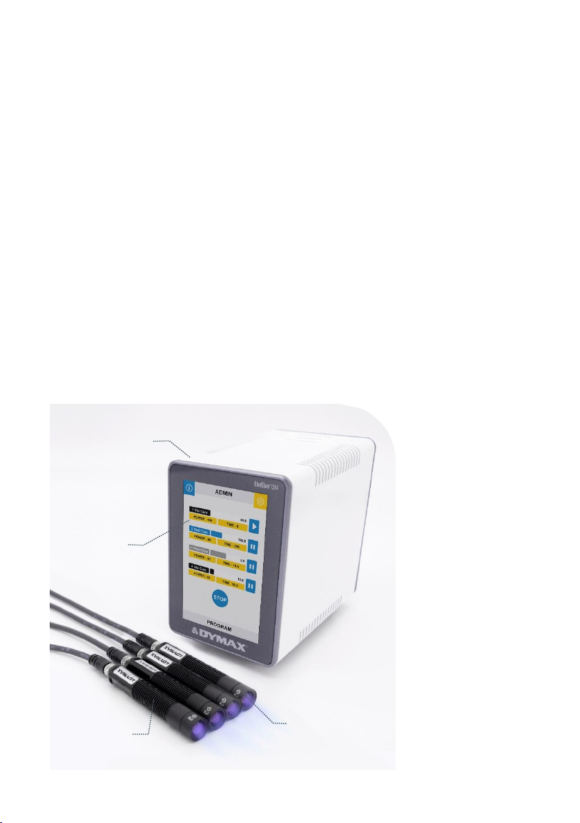
Description of the BlueWave QX4 V2.0.................................. 9
Features & Benefits................................................................... 10
Validation.................................................................................... 11
Front LCD Panel........................................................................ 12
Back Panel ................................................................................. 13
Unpacking..................................................................... 14
Parts Included............................................................................ 15
System Setup ............................................................... 16
System Connections................................................................. 16
LED Heads & Lenses................................................................ 17
Operation...................................................................... 18
ADMIN Mode ............................................................................. 19
PRODUCTION Mode ................................................................ 21
PLC Operation........................................................................... 22
System Settings ........................................................... 31
System Information...................................................... 34
Cleaning & Maintenance.............................................. 35
LED Head Optic Lens ............................................................... 35
Alarm Messages........................................................... 36
Troubleshooting........................................................... 38
Spare Parts and Accessories ...................................... 39
Specifications............................................................... 41
Warranty ....................................................................... 43

4 U S E R G U I D E |B L U E W A V E ®Q X 4 ®
Introduction
This guide describes how to set up, use, and maintain the
BlueWave®QX4 V2.0 LED spot-curing system safely and
efficiently.
Intended Audience
Dymax prepared this user guide for experienced process
engineers, technicians, and manufacturing personnel. If you
are new to high-intensity LED light sources and do not
understand the instructions, contact Dymax Application
Engineering for answers to your questions before using the
equipment.
Where to Get Help
Dymax Customer Support and Application Engineering
teams are available by phone in the United States, Monday
through Friday, from 8:00 a.m. to 5:30 p.m. Eastern
Standard Time. You can also email Dymax at
[email protected]. Contact information for additional Dymax
locations can be found on the back cover of this user guide.
Additional resources are available to ensure a trouble-free
experience with our products:
•Detailed product information on www.dymax.com
•Dymax adhesive product data sheets (PDS) on our
website
•Material safety data sheets (SDS) provided with
shipments of Dymax adhesives

U S E R G U I D E |B L U E W A V E ®Q X 4 V 2 . 0 5
Safety
WARNINGS! If you use this LED light source without first reading
and understanding the information in this user guide, injury can result
from exposure to high-intensity light. To reduce the risk of injury, read
and ensure you understand the information in this user guide before
assembling and operating the Dymax LED light source.
To use the BlueWave QX4 V2.0 system safely, it must be set up and operated in
accordance with the instructions given by Dymax. Using the system in any other
manner will impair the protection of the system. Dymax assumes no liability for any
changes that may impair the protection of the BlueWave QX4 V2.0 system.
General Safety Considerations
All users of Dymax LED light sources should read and understand this user guide
before assembling and using the system.
To learn about the safe handling and use of light-curable formulations, obtain and read
the SDS for each product. Dymax includes an SDS with each adhesive sold. In
addition, SDS can be requested through our website.
Specific Safety Considerations
The BlueWave QX4 V2.0 is designed to maximize operator safety and minimize
exposure to light-curing energy. To use the unit safely, it must be set up and operated
in accordance with the instructions in this user guide. Please also read and understand
the safety considerations unique to LED-curing systems as described below.
WARNINGS! Looking directly at the high-intensity light emitted by the
LED heads of the BlueWave QX4 V2.0 can result in eye injury. To prevent
eye injury, never look directly at the end of the high-intensity LED head and
always wear protective goggles. To avoid accidental exposure, always point
the LED head away and at the curing substrate.
This device falls under IEC 62471 Risk Group 3 for UVA and blue light
emissions:

6 U S E R G U I D E |B L U E W A V E ®Q X 4 ®
WARNING! UV emitted from this product. Avoid eye and skin exposure to
unshielded products.
WARNING! Possibly hazardous optical radiation emitted from this product. Do not
look at operating lamp. Eye injury may result.
Removing the cover from the BlueWave QX4 V2.0 controller may result in electrical
shock. To prevent the possibility of an electrical shock, never remove the controller’s
cover
The controller is cooled by natural convection. If you block the air flow from the
controller, equipment damage and malfunction can result. To prevent damage and
malfunction, ensure adequate space around controller vents to allow the free flow of
air. Typically, 1.5 in of space around all sides of the controller is sufficient.
Dymax UV Light-Curing System Safety Considerations
Operators must understand these three concepts to use the LED light source safely:
UV exposure, high-temperature surfaces, and bright, visible light.
UV Exposure
Figure 1.
UV Spectrum
Standard Dymax UV light-curing systems have been designed primarily to emit UVA
and Visible energy (Figure 1). Depending on the type of LED head used, the energy
emitted from the BlueWave QX4 V2.0 can either be in the upper end of the UVA
portion of the spectrum (PrimeCure®& RediCure®) or in the lower portion of the visible
spectrum (VisiCure®). UVA energy is generally considered the safest of the three UV

U S E R G U I D E |B L U E W A V E ®Q X 4 V 2 . 0 7
ranges: UVA, UVB, and UVC. Although OSHA does not currently regulate UV-light
exposure in the workplace, the American Conference of Governmental Industrial
Hygienists (ACGIH) does recommend Threshold Limit Values (TLVs) for ultraviolet light.
The strictest interpretation of the TLV (over the UVA range) for workers’ eyes and skin
allows continuous exposure up to 1 mW/cm2(intensity). Unless you are placing bare
hands into the curing area, it is unusual to exceed these limits. To put 1 mW/cm2limit
into perspective, a cloudless summer day will typically exceed 3 mW/cm2of UVA light,
and also include the more dangerous UVB light (primarily responsible for sun tans, sun
burns, and skin cancer).
Checking the Workstation
The human eye cannot detect "pure" UV light, only visible light. A radiometer should be
used to measure stray UV light to confirm the safety of a UV light-curing process. A
workstation that exposes an operator to more than 1 mW/cm2of UVA continuously
should be redesigned.
Protecting Operators
Light-curing technology can be a regulatory compliant, "worker-friendly" manufacturing
process when the proper safety equipment and operator training is utilized. There are
two ways to protect operators from UV exposure: shield the operator and/or shield the
source.
Shield the Operator
UV-Blocking Eye Protection —UV-blocking eye protection is recommended when
operating UV light-curing systems. Both clear and tinted UV-blocking eye protection is
available from Dymax.
UV-Blocking Skin Protection —Opaque, UV-blocking clothing, gloves, and full-face
shields are recommended when skin may potentially be exposed to UV light.
Shield the Source of UV
Any substrate that blocks UV light can be used as a shield to protect workers. The
following materials can be used to create simple shielding structures:

8 U S E R G U I D E |B L U E W A V E ®Q X 4 ®
Rigid Plastic Film —Transparent or translucent/UV-blocking plastics (typically
polycarbonate or acrylic) are commonly used to create shielding where some level of
transparency is also desired.
Flexible Film —Translucent UV-blocking, flexible urethane films can be used to
quickly create workstation shielding. This UV-blocking, flexible urethane film is available
from Dymax, call for assistance.
High-Temperature Surfaces
Surfaces exposed to high-intensity curing lights may rise in temperature. The intensity,
distance, exposure time, cooling fans, and composition of the surface can all affect the
rise in surface temperature. In some cases, exposed surfaces can reach temperatures
capable of producing a burn or causing damage to a substrate. In these cases, care
must be taken to ensure either a more moderate surface temperature or appropriate
protection/training for operators. No infrared radiation is produced by these LED
systems, so surface temperatures will be lower than with conventional lamp systems.
Empirical testing should be used to verify the exact temperature rise in each
application.
Bright Visible Light
The bright visible light energy emitted by curing systems can cause eyestrain if proper
eye protection or shielding is not used. The use of tinted eye protection and/or opaque/
tinted shielding can be utilized to reduce eyestrain and address this concern.

U S E R G U I D E |B L U E W A V E ®Q X 4 V 2 . 0 9
Product Overview
Description of the BlueWave QX4 V2.0
The BlueWave QX4 V2.0 high-intensity spot-curing system features all the benefits of
LED-curing technology in a smaller, more versatile unit. This system is comprised of a
power supply, a controller with an easy-to-use control interface, and up to four LED
heads. LED heads are available in 365, 385, and 405 nm and can be outfitted with
3-, 5-, or 8-mm diameter focusing lenses. LED heads and focusing lenses can be used
in any combination and can be operated in constant or variable mode.
The system’s LED heads can be used as hand-held units or integrated into an automated
manufacturing system allowing for maximum application flexibility. Their output intensity
levels can also be adjusted from 10% to 100% to meet process and adhesive
requirements.
Figure 2.
Main Components of a BlueWave QX4 V2.0
LED Heads
Focusing Lenses
Controller
Front LCD
Panel

10 U S E R G U I D E |B L U E W A V E ®Q X 4 ®
Features & Benefits
The Dymax BlueWave QX4 V2.0 is engineered for precise performance and long
service life. Key features include:
Features
Benefits
One controller operates up
to four LED heads
•Provides maximum application flexibility
LED heads are available in
365, 385, or 405 nm
wavelengths
•Compatible with a variety of UV and visible light-curable
materials
•Wavelengths can be mixed to produce optimal cures
•Units can be custom configured to curing requirements
Variable mode allows each
LED head to be
programmed independently
•Exposure times and intensity settings can be set in 1%
increments for each LED head individually, allowing
maximum curing flexibility
•Timer mode from 0.1 to 999 seconds
Interchangeable/replaceable
focusing lenses in 3-, 5-,
and 8-mm diameters
•Allows tailoring of the unit to your curing requirements
Instant on-off
•No warm-up period
•More energy efficient
Highly flexible interconnect
cables with quick connect
for LED heads
•Can be subjected to frequent movement, with small bend
radius
•Flexible cables are more resilient and pliable than typical
lightguides
•Can be daisy chained up to 10 m for separated workstations
•Easy to handle and switch LED heads
Efficient LED-head
temperature management
•Maximized continuous operation without overheating
•Comfortable hand-held operating temperature; no PPE
required
•Temperature monitoring assures maximum LED life
PLC interface with
4-channel mode
•Easily incorporated into automated systems
Enhanced full touch screen
HMI
•Easy to use, navigate and program
•Recipe storage for up to 20 programs
Cross platform compatibility
•LED heads are compatible with the BlueWave®MX-series
multi-channel controllers when used with the MX-4E
expansion module

U S E R G U I D E |B L U E W A V E ®Q X 4 V 2 . 0 11
Validation
Tests should be conducted prior to production to determine the time and light intensity
required to fully cure your material. The following approaches may be used to validate
the curing process.
Set Exposure Time, Determine Intensity
Users can specify a cure time and, through empirical testing, determine the intensity
required to achieve a full cure. As with any manufacturing process, it is advisable to
incorporate a safety factor.
Set Intensity, Determine Exposure Time
Users can specify light intensity and, through empirical testing, determine the exposure
time required to achieve a full cure. As with any manufacturing process, it is advisable
to incorporate a safety factor.
Control
Process validation confirms a minimum acceptable intensity. Users can then choose to
operate at full intensity (using the excess intensity as an additional safety factor) or
adjust the output to a specific intensity level. To ensure consistent and repeatable
process results, intensity levels should be monitored with a radiometer. This enables
users to identify light intensity changes and take corrective action (either adjusting the
light intensity or performing maintenance).

12 U S E R G U I D E |B L U E W A V E ®Q X 4 ®
Front LCD Panel
Front LCD Display —Displays the currently selected menu.
System Information —Used to check the version of the system and the accumulated
usage time.
System Setting —Used to set the configuration of the system, including language,
brightness, and user initialization settings.
User Mode Setting—Toggles between ADMIN and PRODUCTION modes.
ADMIN: The system default ADMIN interface. The user will have the highest
authority and can modify the parameters of the light and system configuration.
PRODUCTION: The PRODUCTION interface. The user can only modify the
brightness of the screen. A password is needed to switch to the ADMIN interface.
Power Setting —Used to set the exposure power.
Time Setting —Used to set the exposure time.
LED Head Type Indicators —Colored lights indicate the type of each connected LED
head. A black light indicates the LED head type is VisiCure –405 nm. A blue light
indicates the LED head type is RediCure –365 nm. A gray light indicates the LED head
type is PrimeCure –385 nm.
Progress Bar Indicators —Indicates the current progress of each LED head.
Count Down Timer —Counts down from the setting time.
Single Channel Run/Stop Control —Each LED head can be run or stopped by
pressing each channel icon of and separately.
All Channels Run/Stop Control —All LED heads can be run or stopped by pressing
the icon of or .
Alarm Indicators —Indicates system faults.
Parameters Save/Load—Indicates the name of the current parameters setting.

U S E R G U I D E |B L U E W A V E ®Q X 4 V 2 . 0 13
Figure 3.
Front LCD Panel
Front LCD
Display
Alarm
Indicators
All Channels
Run/Stop Control
System Setting
User Mode Setting
System
Information
Single Channel
Run/Stop Control
Power Setting
LED Head Type
Indicators
Time Setting
Parameters
Save/Load
Progress Bar Indicators
Count Down Timer

14 U S E R G U I D E |B L U E W A V E ®Q X 4 ®
Back Panel
Power Cord Receptacle —Connection point for the power cord.
On/Off (I/O) Switch —Moving the switch to the on position (I) powers up the
controller. Moving the switch to the off position (O) cuts power to the controller.
Footswitch Connection Jacks —Up to 4 footswitches can be used as optional
irradiation triggers. Pressing the footswitch starts a curing cycle. In timed operation,
pressing and releasing the footswitch initiates the curing cycle. A second press will
terminate a timed cure cycle immediately.
PLC Connector Terminal —Connection points for interfacing with a user-supplied
PLC. See the PLC Operation Section for more details.
RS232 Port —No functionality, provided for factory troubleshooting.
LED Head Connection Jacks —Connection points for up to four LED heads. Each
connector corresponds to an available channel and indicator on the LCD display.
Figure 4.
Back Panel Controls & Connections
PLC
Connector
Terminal
On/Off
Switch
RS232 Port
LED Head Connection
Jacks (CH1-CH4)
Power Cord
Receptacle
Footswitch Connection
Jacks (FS1-FS4)

U S E R G U I D E |B L U E W A V E ®Q X 4 V 2 . 0 15
Unpacking
Upon arrival, inspect all boxes for damage and notify the shipper of box damage
immediately. Open each box and check for equipment damage. If parts are damaged,
notify the shipper and submit a claim for the damaged parts. Contact Dymax so that
new parts can be shipped to you immediately.
Check that the parts included in your order match those listed below. If parts are
missing, contact your local Dymax representative or Dymax Customer Support to
resolve the problem.
Parts Included
Controller
•Controller
•Power Adapter
•Power Cord
•Footswitch
•Safety Glasses
•BlueWave QX4 V2.0 User Guide
LED Heads
•LED Head Assembly
•Accessory Focusing Lenses
•PLC Connection Terminals
Note: Extra connection cable extensions
can be ordered as accessories.

16 U S E R G U I D E |B L U E W A V E ®Q X 4 ®
System Setup
System Connections
Power Cable Connection —Attach the Power Cord to the Power Cord Receptacle
located on the unit’s back panel (Figure 4). Press the Power Cord firmly into the
receptacle until it clicks and locks into place. The unit is now powered and ready to be
turned on with the On/Off Switch.
To remove the Power Cord, pull the retaining body of the Connector to unlock it from
the receptacle.
LED Head Connection Jacks —Along the right of the Controller’s Rear Panel, there
are four LED Head Connection Jacks labeled CH 1 - 4. The Connectors are keyed so
they may require slight rotation to align with the keying elements of the connector pair.
Once the keyways are aligned, press the LED Head Connector into the Jack until it
clicks and locks in place.
NOTE: DO NOT rotate the Connectors once installed, they are not threaded, and
damage may occur.
To remove the LED Head, grasp the metal Outer Retaining Ring Body of the Connector
and pull away from the Controller to unlock it from the Jack.
Footswitch Connection (Optional) —Located on the middle of the Controller’s rear
panel. It can be used as an optional irradiation trigger.
PLC Connection Terminals —There are input and output PLC Connection Terminals
that can be used to integrate the unit to an automated assembly line. See the PLC
Operation Section for more details.
A low signal (0V) input on PLC_ENABLE switches the QX4 to PLC mode. In PLC mode,
the Front Control Display displays the PLC connection and locks out the screen input.
A high signal (24V) input on MASTER INTERLOCK locks out all the channel output.

U S E R G U I D E |B L U E W A V E ®Q X 4 V 2 . 0 17
LED Heads & Lenses
The BlueWave QX4 V2.0 led heads are available in three different wavelengths: 365 nm
(RediCure), 385 nm (PrimeCure), and 405 nm (VisiCure). Each LED head is made up of
three main components: the handle, a collimating lens, and a focus lens. LED head
assemblies are 1.0 M in length. Extensions can be purchased for extra length.
Extension cables can be used for up to 10 meters additional length in any combination.
Figure 5.
LED Head Components
The wavelength of the LED head is noted on a label on handle. Collimating and
focusing lenses on each LED head are interchangeable, but the handle is unique to a
specific wavelength.
Figure 6.
Color-Coded LED Heads
Figure 7.
Focus Lenses
RediCure, 365 nm
PrimeCure, 385 nm
VisiCure, 405 nm
Handle
Collimating Lens
Focus Lens
Cooling Fins

18 U S E R G U I D E |B L U E W A V E ®Q X 4 ®
The focusing lenses indicate the spot sizes that are generated at a 5-mm working
distance. The UV energy is focused on that spot and provides maximum output and
uniformity of the spot.
As you change working distance, the intensity and spot size will change. It is best to
review the product bulletin to ensure you are using the correct lens and working
distance combination to achieve the target exposure.
If you are using larger working distances, you may have better results removing the
focusing lens and using the collimating lens for spot generation.
Fixturing
If you are fixturing the LED head, do not cover the cooling fins, or overheating can
result. We suggest clamping on the flat portion of the handle with non-marring screws
or split ring clamps.
Figure 8.
Fixturing Recommendations
Do Not Cover
Cooling Fins
Attach Fixture to the
Flat Section of the Handle

U S E R G U I D E |B L U E W A V E ®Q X 4 V 2 . 0 19
Operation
WARNING! Looking directly at the high-intensity light emitted by the
heads of the BlueWave QX4 V2.0 can result in eye injury. To prevent eye
injury, never look directly at the high-intensity light and always wear
protective goggles (provided).
Verify that all connectors are firmly plugged
into the rear panel of the unit. See System
Connections, pg. 16 for more details.
On the rear panel of the controller, move
the Power Switch to the on position (I). The
system is now ready for use.
On the first startup, the system defaults to
ADMIN mode. The boot mode can be set
through the User Interface in System
Settings .
ADMIN Mode
ADMIN mode allows the user to configure
each LED head at a predefined (constant)
power output for a given amount of time.
Each head can be adjusted independently.
If the current mode is not ADMIN
mode, you need to enter the password
to return to the ADMIN mode.
Default Password:1234
Figure 9.
Main Menu Screen in ADMIN
Mode
Figure 10.
Return to ADMIN Mode by
Entering the Password

20 U S E R G U I D E |B L U E W A V E ®Q X 4 ®
Set Up
In the ADMIN mode menu, the user can see the current power and time configuration
for each one of the LED heads. To update any LED head, navigate to the LED head by
pressing the POWER or TIME icons. The selected option will open a value input
window. Press the pad’s button to edit. Any LED head that is not connected displays a
N/A red icon. The user can still select and program any red-out rows, but the unit will
not run the program for the disconnected LED head.
Another screen will show the power (Figure 12). Input the required power directly
through the numeric keypad. The power can be set from a value of 10-100%, at 1%
increments.
When editing is finished, press the return key in the upper left corner to go back to the
ADMIN model menu.
Another screen will show the time (Figure 13). Input the required working time directly
through the numeric keypad. The time can be set from a value of 0-999s.
When editing is finished, press the return key in the upper left corner to go back to the
ADMIN model menu.
If the time is set to 0s, the LED head stays on until it is stopped manually.
Figure 11.
ADMIN Mode Menu
Figure 12.
Power Editing Screen
Figure 13.
Time Editing Screen
Other manuals for BlueWave QX4 V2.0
1
Table of contents