Dyna-Flo DFR 070 Parts list manual

Model DFR 070/156/220 Rotary Actuator
Dyna-Flo Control Valve Services Ltd.
Phone: 780 •469 •4000 Toll Free: 1 •866 •396 •2356 Fax: 780 •469 •4035 Website: www.dynaflo.com
P-DFR3M0919A 1
Operation, Parts, and Instruction Manual
TABLE OF CONTENTS
General 2 Actuator Assembly 18
Scope 2 Bushing / Yoke Assembly 18
Principles of Operation 2 Spring Barrel Assembly 18
Safety Caution 2 Diaphragm Plate Assembly 20
Specifications 3 Diaphragm Casing Assembly 21
Unpacking 4 Lever Installation 22
Installation 4 Cover Plate Assembly 23
Air Piping 4 Cover Plate Installation 23
Actuator Mounting 5 Plate Installation 23
Actuator Adjustment 8 Actuator Cross Section - Figure 26 24
Spring Adjustment 10 Principles of Handwheel & Travel Stop Operation 25
Actuator Conversion 11 Maintenance - Handwheels & Travel Stops 25
Changing Actuator Style 12 Mounting Bolt Torques - Table 3 29
Actuator Disassembly 14 DFR Torque Specifications - Table 4 29
Cover Plate Disassembly 15 Open-End Wrench Sizes - Table 5 29
Lever Removal 15 Parts 30
Diaphragm Casing Disassembly 15 Model Builder 36
Spring Barrel Disassembly 16
Yoke Removal 17
Plate Removal 18
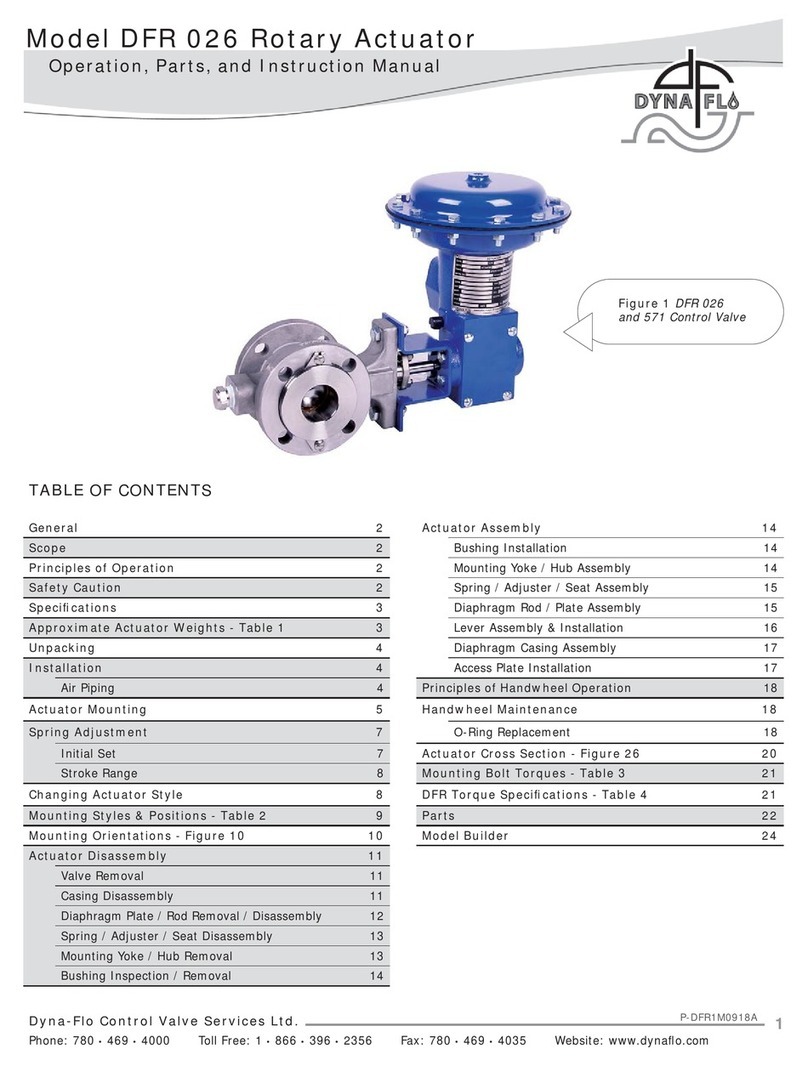
Figure 1 DFR 156

Dyna-Flo Control Valve Services Ltd.
Phone: 780 •469 •4000 Toll Free: 1 •866 •396 •2356 Fax: 780 •469 •4035 Website: www.dynaflo.com
Model DFR 070/156/220 Rotary Actuator
P-DFR3M0919A 2
Operation, Parts, and Instruction Manual
NOTICE These instructions are meant to be used with the Dyna-Flo DFR Technical Sales Bulletin as they refer to
Figures and Tables therein. If you do not have the Technical Sales Bulletin, contact Dyna-Flo immediately,
or visit www.dynaflo.com.
Each control valve is factory checked. Check the calibration for the specific application, before a valve
or actuator is put into service.
It is the intention of this document to provide users with an accurate guide for safe installation and
maintenance of the DFR Actuator. Revisions and updates are available at above mentioned website.
GENERAL
The following instructions are to be thoroughly reviewed and understood prior to installing, operating or performing
maintenance on this equipment. Work on this equipment should be performed by experienced personnel. Throughout
the manual, safety and caution notes appear and must be strictly followed to prevent serious injury or equipment
malfunction.
SCOPE
The actuator configuration and construction materials were selected to meet particular pressure, temperature, operating medium,
and process fluid conditions. Some material combinations are limited in their pressure and temperature ranges. Do not apply any
other conditions to the actuator without first contacting your Dyna-Flo sales office.
This manual is written to be a practical and useful guide for maintaining the Dyna-Flo DFR Actuator.
SAFETY CAUTION
Only well trained experienced technicians should perform these procedures. Use safe work practices and lock out
procedures when isolating valves and actuators. It is also important to wear the proper protective equipment when
performing any installation or maintenance activity. Use only parts and materials rated for the process being used,
operating conditions, and environmental conditions products will be used in.
To avoid personal injury or installation damage as a result of the sudden release of process pressure or damage to
equipment, do not install the actuator assembly where service conditions could exceed the limits stated in this manual,
sales bulletin or on the equipment nameplates. Use government codes, accepted industry standards and good piping
practices, and select proper pressure-relieving equipment for protection of your installation. Always be aware of
flammable process and instrument gas.
Always be aware of the hazards of actuators, especially spring-loaded actuators. Be sure that the actuator is
de-energized or in the failed position before performing any maintenance procedure.
These actuators have dangerous pinch points. Never put your hands inside the valve or actuator unless you are certain
that the valve or actuator will not suddenly move.
PRINCIPLES OF OPERATION (For Top-Mounted Handwheels and Travel Stops refer to Page 25)
The DFR actuator works by loading pressure on the top side of the diaphragm (Key 21), this loading pressure moves the diaphragm
rod (Key 20) downwards. As the loading pressure is decreased, the spring (Key 19) forces the diaphragm rod upwards.
The spring and diaphragm have been selected to meet a specific application requirement, and while in service the actuator should
produce full travel of the valve with the diaphragm pressure indicated on the nameplate (Key 50).
If there is no positioner being used with the control valve, a loading device (such as a 4-way switching valve) must be used. Loading
devices do not come equipped standard with the actuator. Refer to appropriate positioner instruction manual as required.

Model DFR 070/156/220 Rotary Actuator
Dyna-Flo Control Valve Services Ltd.
Phone: 780 •469 •4000 Toll Free: 1 •866 •396 •2356 Fax: 780 •469 •4035 Website: www.dynaflo.com
P-DFR3M0919A 3
Operation, Parts, and Instruction Manual
SPECIFICATIONS
Material Temperature Capabilities
Standard: -40 to 180 oF (-40 to 82 oC).
Construction Materials
Refer to Parts list for construction materials.
Contact your Dyna-Flo sales office for more information and
other options.
Valve Shaft Compatibility, inches (mm)
Size 070: 1/2 (12.7), 5/8 (15.9), 3/4 (19.1), 7/8 (22.2),
1 (25.4)
Size 156: 3/4 (19.1), 7/8 (22.2), 1 (25.4), 1-1/4 (31.8),
1-1/2 (38.1)
Size 220: 1-1/4 (31.8), 1-1/2 (38.1), 1-3/4 (44.5),
2 (50.8)
* 7/8” shaft only available for a 4” 570.
Actuator Dimensions
Refer to Figures 3 & 4 of Sales Bulletin.
Refer to Tables 2, 3, & 4 of Sales Bulletin.
Output Torque
Refer to Tables 5 to 7 of Sales Bulletin.
Actuator Mounting Orientation Valve Applications
Refer to Figure 12.
Refer to Table 2.
Other Applications
Please specify with a sketch.
Tubing Connection Size
All sizes, 1/4 inch NPT standard. Other sizes available.
Maximum Shaft Rotation
90 degrees.
Shaft Connection Types
The standard shaft connection is a splined shaft suitable for a
Dyna-Flo 570 control valve. A square stub or keyed
connection is also available.
Options
•Manual override
•Reduced rotation output
•Increased tubing connection size
•Travel stops
Diaphragm Casing Volume
Refer to Table 8 of Sales Bulletin.
For more information and other options contact your Dyna-Flo
sales office.
Actuator Size Maximum Casing
Pressure Psig (kPag)
070 75 (517)
156 50 (345)
220 65 (448)
Table 1
Approximate Actuator Weights - lb. (Kg)
Actuator Size Standard Assembly With Top Mounted Handwheel
070 99 (45) 115 (52.3)
156 203 (92) 227 (103)
220 272 (123) 319 (144)

Dyna-Flo Control Valve Services Ltd.
Phone: 780 •469 •4000 Toll Free: 1 •866 •396 •2356 Fax: 780 •469 •4035 Website: www.dynaflo.com
Model DFR 070/156/220 Rotary Actuator
P-DFR3M0919A 4
Operation, Parts, and Instruction Manual
UNPACKING VALVE FROM SHIPPING
CONTAINER
Special Tools Required:
• Properly Rated Lifting Straps (2 – 4 Straps) See Table 1 for
actuator weights.
• Lifting Device (Example: Crane)
Check the packing list, verify that the list includes all the
materials in the shipping container before unpacking. Valve
information can be found on the nameplate (Key 50). Refer to
Figure 3 for nameplate location.
When lifting the valve from shipping container, place properly
rated ifting straps securely around the neck of the actuator,
refer to Figure 2 for strap placement. Straps should be placed
to avoid damage to tubing and other mounted accessories.
Lift the valve/actuator assembly using proper lifting techniques.
AIR PIPING
WARNING:
Property damage, environmental harm, and personal injury
can result from the use of supply gas other than clean,
non-corrosive, oil and moisture free air. Do not exceed the
supply pressure indicated on the nameplate (Key 53)
located on the actuator.
Before You Begin:
Note: Standard actuators accept 1/4” (6 mm) NPT connections.
Size 220 actuators have a threaded reducer bushing (Key 25)
that reduces the casing (Key 24) NPT connection from 1/2”
(12.7 mm) to 1/4” (6 mm), the bushing fitting is removable
(refer to Figure 9).
Piping Installation Steps:
1Use 3/8” (10 mm) outside diameter SST tubing
(or equivalent) for air lines. Keep length of tubing as short
as possible to prevent transmission lag in the control
signal.
2Install the required line vents, valves, drains, seals, and
filters to the actuator.
INSTALLATION
Before You Begin:
• Read the General and Scope section of this manual (Page 2).
• Read Safety Caution (Page 2).
• Sudden movement of actuator can cause damage or injury.
It helps to have the actuator de-energized as long as the
valve installation will permit.
• Use safe work practices and lock out procedures before
placing valve in-line.
Actuators are typically shipped from factory as an assembly
already mounted to the valve. Follow the appropriate valve
installation instructions to install the actuator / valve assembly.
If the actuator was shipped separately, it will be necessary to
mount the actuator on the valve prior to installation, refer to
the Actuator Mounting section.
Operating medium must be controlled and directed, if a
positioner was not ordered or unavailable, use a loading
device such as a 4-way switching valve (not provided with the
actuator). For more information on positioner installation and
operation, refer to the appropriate positioner instruction
manual for your positioner type.
Figure 2 Suggested Lifting Strap Placement
LIFTING STRAP

Model DFR 070/156/220 Rotary Actuator
Dyna-Flo Control Valve Services Ltd.
Phone: 780 •469 •4000 Toll Free: 1 •866 •396 •2356 Fax: 780 •469 •4035 Website: www.dynaflo.com
P-DFR3M0919A 5
Operation, Parts, and Instruction Manual
ACTUATOR MOUNTING
Before You Begin:
• Read the General and Scope section of this manual (Page 2).
• Read Safety Caution (Page 2).
• Use safe work practices and lock out procedures.
• Disconnect supply lines (air or gas), electric power, or control
signal to the actuator. Sudden movement of actuator can
cause damage or injury, make sure actuator will not operate.
• Vent any pneumatic actuator loading pressure.
• Relieve process pressure and drain the process fluid from up
and down stream of valve.
• Be aware of potentially hazardous process material that may
be present in-line and in-valve. Isolate the valve from
process pressure. Use a bypass or block valve if necessary,
or completely shut off the process. Relieve internal valve
pressure (refer to the appropriate valve instruction manual).
Lubricants Required:
• Anti-Seize Compound (Key A)
• Refined Petroleum Oil (Key E)
1If the valve has been removed from the pipeline, secure
the valve assembly in place on a flat work surface
that will support the weight of the combined valve and
actuator assembly.
2Remove any positioners and/or instrumentation installed
on the actuator.
3Remove the cover plate cap screws (Key 45) and washers
(Key 44).
4Remove the cover plate/bushing assembly (Keys 36, 37,
38, 39, 40, 41, 42, and 43).
5If the lever (Key 32) is attached to the rod end bearing
(Key 31), disconnect the lever from the rod end bearing
by removing the cap screw (Key 34) and hex nut (Key 35).
Remove the lever.
6Slide the actuator onto the valve shaft as shown in Figure
5. Refer to Figures 6 and 12 for actuator mounting
positions and orientations. Note: The actuator is typically
installed in a vertical orientation. Should the actuator be
installed in a horizontal position, then it may be necessary
to have external support for the actuator in this position. Figure 3 Cover Plate Assembly Removal
50
45
38
36
42
44
31
35
34
32
6
6

Dyna-Flo Control Valve Services Ltd.
Phone: 780 •469 •4000 Toll Free: 1 •866 •396 •2356 Fax: 780 •469 •4035 Website: www.dynaflo.com
Model DFR 070/156/220 Rotary Actuator
P-DFR3M0919A 6
Operation, Parts, and Instruction Manual
Figure 4 Turnbuckle Assembly Adjustment
ACTUATOR MOUNTING (Continued)
7Once the actuator is installed on the valve shaft in the
proper orientation, secure the actuator in place using the
mounting bolts (Key 3) and lockwashers (Key 4) for
Model 590 valves (refer to Figure 5. Mounting to Model
570 valves will require a hex nut (Key 5). Refer to Table
3 for torque values.
Note: See Table 5 for required wrench sizes for turnbuckle
assembly adjustment for Steps 8 - 11.
8Turn the hex nut (Key 28) until it reaches the top of the
threaded portion of the diaphragm rod (Key 20). Leave the
hex nut finger tight, it will be re-adjusted later.
9Turn the turnbuckle (Key 29) until it makes contact with
the hex nut (Key 28) at the top of the diaphragm rod (Key
20). Leave the turnbuckle finger tight, it will be re-adjusted
later.
10 Turn the lower hex nut (Key 30) down onto the rod end
bearing (Key 31) as far as it will go. Leave the hex nut
finger tight, it will be re-adjusted later.
11 Thread the rod end bearing (Key 31) into the turnbuckle
(Key 29) as far as it will go. Leave the rod end bearing
finger tight, it will be adjusted later.
12 Lubricate the teeth of the valve shaft spline with refined
petroleum oil (Key E).
13 Loosen the lever clamp cap screw (Key 33).
14 Install the lever onto the valve shaft (Key V). Refer to
Figures 6 and 12, and the appropriate valve instruction
manual for proper lever orientation.
15 Adjust the position of the lever (Key 32) so that the rod
end bearing (Key 31) will be in alignment between the cap
screw holes of the lever. Note: Refer to Figure 7 for lever
operating clearance. It may be necessary to remove the
positioner plate (Key 46) or the access plate (Key 48) in
order to verify the lever operating clearance.
16 Connect the lever (Key 32) to the rod end bearing (Key
31). Refer to Figure 6:
AInstall the cap screw (Key 34) through the lever
(Key 32) and rod end bearing (Key 31). Note: It
may be necessary to adjust the turnbuckle (Key 29)
in order to meet alignment.
20
28
29
30
31
TURN UP
TURN UP
TURN DOWN
TURN UP
STEPS 8 -10
STEP 11
NOTE: NUT IS
LEFT HAND
THREADED

Model DFR 070/156/220 Rotary Actuator
Dyna-Flo Control Valve Services Ltd.
Phone: 780 •469 •4000 Toll Free: 1 •866 •396 •2356 Fax: 780 •469 •4035 Website: www.dynaflo.com
P-DFR3M0919A 7
Operation, Parts, and Instruction Manual
ACTUATOR MOUNTING (Continued)
16 Connect the lever (Key 32) to the rod end bearing (Key
31). (Continued)
BThread the hex nut (Key 35) onto the cap screw
(Key 34) and tighten to the torque value specified in
Table 4.
Figure 5 Valve/Actuator Mounting
Figure 6 Lever Installation and Orientation Options
43
V
6
2
E32
33
32
V
ALIGNING THE MARK ON THE
VALVE SHAFT (KEY V) WITH
THOSE ON THE LEVER (KEY 32)
PRODUCES THE 4 POSSIBLE
ACTUATOR POSITIONS AS
SHOWN IN FIGURE 12.
33 35
34
V
32
33
32
31
5
3
4
590
VALVE
570
VALVE
MOUNTING
VIEW EXAMPLE
FOR A DFR TO
590 VALVE

Dyna-Flo Control Valve Services Ltd.
Phone: 780 •469 •4000 Toll Free: 1 •866 •396 •2356 Fax: 780 •469 •4035 Website: www.dynaflo.com
Model DFR 070/156/220 Rotary Actuator
P-DFR3M0919A 8
Operation, Parts, and Instruction Manual
ACTUATOR ADJUSTMENT
Before You Begin:
• Read the General and Scope section of this manual (Page 2).
• Read Safety Caution (Page 2).
• Use safe work practices and lock out procedures.
• Disconnect supply lines (air or gas), electric power, or control
signal to the actuator. Sudden movement of actuator can
cause damage or injury, make sure actuator will not operate.
• Vent any pneumatic actuator loading pressure.
• Relieve process pressure and drain the process fluid from up
and down stream of valve.
ACTUATOR MOUNTING (Continued)
15 Check the position of the valve ball or disk and note the
direction of rotation for valve operation.
For actuators without a handwheel:
ARe-install the cover plate assembly (Keys 36, 37,
38, 39, 40, 41, 42, and 43). Position the cover plate
assembly so that the travel indicator (Key 42) will
rotate according to the position of the valve ball/disk
and direction of valve operation as determined
above.
BApply anti-seize compound (Key A) to the threads of
the cap screws (Key 45) and secure the cover plate
(Key 36) in place using the washers (Key 44) and
cap screws. Torque the cap screws to the
recommend torque value listed in Table 4.
Note: If the holes of the actuator housing (Key 6)
and the cover plate (Key 36) are out of alignment, it
may be necessary to loosen the mounting yoke cap
screws (Key 7) and reposition the actuator housing.
DO NOT stroke the actuator while the cover plate is
removed.
For actuators with a manual handwheel:
ARefer to the Top Mounted Handwheel section of this
manual (Page 25).
16 Refer to the Actuator Adjustment section for instructions
on re-adjusting the turnbuckle assembly.
Figure 7 Lever Operating Clearance
• Be aware of potentially hazardous process material that may
be present in-line and in-valve. Isolate the valve from
process pressure. Use a bypass or block valve if necessary,
or completely shut off the process. Relieve internal valve
pressure (refer to the appropriate valve instruction manual).
Special Tools Required:
• Regulated air supply (to stroke the actuator).
• Wrenches (See Table 5 for open-end wrenches required for
turnbuckle adjustment).
Note: When the turnbuckle (Key 29) is properly adjusted,
the valve will be completely closed or open when the actuator
is against its travel stops (Keys 17 & 18). For accurate zero-
degree valve ball or disk position adjustment, the control valve
must be removed from the pipeline and the actuator may also
need to be removed from the valve (Refer to the appropriate
valve instruction manual).
OPERATING CLEARANCE
SIZE 070 TO 220 = 1/16” (1.6 mm)
SIZE 070 TO 220 = 1-3/8” (34.9 mm)

Model DFR 070/156/220 Rotary Actuator
Dyna-Flo Control Valve Services Ltd.
Phone: 780 •469 •4000 Toll Free: 1 •866 •396 •2356 Fax: 780 •469 •4035 Website: www.dynaflo.com
P-DFR3M0919A 9
Operation, Parts, and Instruction Manual
ACTUATOR ADJUSTMENT (Continued)
1Remove the cap screws (Key 49) and access plate
(Key 48). Note: DO NOT remove the cover plate assembly
(Keys 36, 37, 38, 39, 40, 41, 42, 43, 44, & 45) during
actuator adjustment. The cover plate assembly supports
the valve shaft (Key V) and should never be removed
when stroking the actuator. Refer to Figure 8.
2Loosen the lower hex nut (Key 30) through the access
plate opening (where Key 48 was removed in Step 1).
3Apply enough operating pressure to the diaphragm casing
to stroke the actuator until the left-hand threaded hex nut
(Key 28) can be accessed through the access plate
opening. Loosen the hex nut. Refer to Figure 8.
4For Push-Down-to-Close Actuator/Valve Configurations:
Refer to the appropriate valve instruction manual in order
to determine the closed position of the valve.
ASlowly stroke the actuator down until the maximum
operating pressure is reached. Make note of the
valve ball/disk position. Refer to Figure 8 & 9.
BAdjust the turnbuckle (Key 29) as needed until the
valve reaches the closed position, indicated on the
travel scale (Key 38). Refer to Figure 8.
CCheck the thread engagement of the rod end
bearing (Key 31) into the turnbuckle (Key 29).
Adequate thread engagement will be approximately
equal to the diameter of the threads of the rod end
bearing.
D Lock the turnbuckle (Key 29) in place using the left-
hand threaded hex nut (Key 28), do not overtighten.
ESlowly remove operating pressure until the actuator
reaches mid-travel position. Fully tighten the locknut
(Key 30) to the torque value indicated in Table 4.
For Push-Down-to-Open Actuator/Valve Configurations:
Refer to the appropriate valve instruction manual in order to
determine the closed position of the valve.
ARelease all operating pressure from the diaphragm casing,
make sure that the diaphragm (Key 21) is resting against
the up travel stop. Refer to Figure 9.
Note: If the actuator is equipped with a top mounted
handwheel, adjust the handwheel to its topmost position.
Adjusting the handwheel will ensure that the zero position
of the actuator and valve can be reached simultaneously. Figure 8 Turnbuckle Adjustment
OPEN OPEN
CLO SED
49 48
31
30
29
28
29
20
20
28
29
30
31
ADJUST KEY 29 UP OR
DOWN UNTIL THE
TRAVEL INDICATOR IS IN
THE DESIRED POSITION
(STEP 4B OR 4C)
NO OPERATING
PRESSURE
WITH OPERATING
PRESSURE

Dyna-Flo Control Valve Services Ltd.
Phone: 780 •469 •4000 Toll Free: 1 •866 •396 •2356 Fax: 780 •469 •4035 Website: www.dynaflo.com
Model DFR 070/156/220 Rotary Actuator
P-DFR3M0919A 10
Operation, Parts, and Instruction Manual
ACTUATOR ADJUSTMENT (Continued)
4For Push-Down-to-Open Actuator/Valve Configurations:
(Continued)
B Make note of the valve ball/disk position.
CApply operating pressure to the actuator until the
turnbuckle (Key 29) is accessible through the access plate
(Key 48) opening. Adjust the turnbuckle, valve ball/disk
should visibly rotate accordingly. Refer to Figure 8.
DRelease all operating pressure from the diaphragm casing
and check the new adjusted position.
EAgain, apply operating pressure to the diaphragm casing
until the turnbuckle (Key 29) is accessible through the
access plate (Key 48) opening. Repeat Steps B to D until
the control valve is in its closed position when the
diaphragm (Key 21) is resting against its up travel stop
(Key 24). Refer to Figure 9.
FSlowly apply operating pressure until the actuator
reaches mid-travel position. Fully tighten the locknut
(Key 30) against the turnbuckle (Key 29) to the torque
value indicated in Table 4.
EStroke the actuator until the left-hand threaded locknut
(Key 28) is accessible through the access plate (Key 48)
opening. Fully tighten the locknut against the turnbuckle
(Key 29) to the torque value indicated in Table 4.
Figure 9 Actuator Operation
5Re-install the access plate (Key 48) using the 4 cap screws
(Key 49). Refer to Figure 8.
6If necessary, re-adjust the actuator travel indicator (Key 42)
appropriately by loosening the screws (Key 43) and
re-tightening them once the travel scale is repositioned.
SPRING ADJUSTMENT - INITIAL SET
Before You Begin:
• Read Before You Begin of the Actuator Adjustment section
(Page 8).
Special Tools Required:
• Regulated air supply (to stroke the actuator).
• Metal rod for adjusting the spring adjuster (Key 14):
- For Size 070 Actuators - 3/8” (9.5 mm) diameter rod.
- For Size 156 Actuators - 5/8” (15.9 mm) diameter rod.
- For Size 220 Actuators - 3/4” (19.1 mm) diameter rod.
Refer to the actuator nameplate (Key 50) for the Initial Set.
The initial setting is the casing pressure at which the diaphragm
(Key 21) begins to move the diaphragm plate (Key 22) and
diaphragm rod (Key 20) away from the up travel stop when
the actuator is not attached to the valve. When the actuator
is connected to a valve with pressure applied to that valve, a
higher casing pressure will be required to begin actuator travel.
817
20
15
22
21
OPERATING PRESSURE SUPPLY LINE
UP TRAVEL STOP
022
19
DOWN
TRAVEL
STOP
24
OPERATING PRESSURE
APPLIED TO DIAPHRAGM
25 DFR220 ONLY

Model DFR 070/156/220 Rotary Actuator
Dyna-Flo Control Valve Services Ltd.
Phone: 780 •469 •4000 Toll Free: 1 •866 •396 •2356 Fax: 780 •469 •4035 Website: www.dynaflo.com
P-DFR3M0919A 11
Operation, Parts, and Instruction Manual
SPRING ADJUSTMENT - INITIAL SET
(Continued)
The initial setting was selected to meet a specific set of service
condition requirements. Proper initial setting will ensure that
once the actuator and valve are in service, the valve will seat
properly and full travel will be achieved within the specified
diaphragm casing pressure range.
Note: If the actuator has been disassembled and reassembled,
or if service requirements have changed, it will be necessary to
perform the following steps for Initial Setting.
1 Disconnect the lever (Key 32) from the rod end bearing
(Key 31) by removing the cap screw (Key 34) and hex nut
(Key 35).
2Apply operating pressure to the diaphragm casing, when
the spring is properly adjusted, the diaphragm rod (Key
20) will start to move when the Initial Set pressure
(indicated on the nameplate (Key 50) or in Table 7) is
reached. Make note whether the diaphragm rod started to
move before or after the Initial Set value. Be careful that
the rod end bearing (Key 31) does not hit the lever (Key
32) when the diaphragm rod (Key 20) begins to move.
3Relieve actuator casing pressure.
4Using the metal adjusting rod (refer to Special Tools
Required), adjust the spring adjuster (Key 14) accordingly:
• To increase Initial Setting – Turn the spring adjuster up
towards the diaphragm casing (Key 15).
• To decrease Initial Setting – Turn the spring adjuster
down towards the actuator housing (Key 6)
5Repeat Steps 2 – 4 until the Initial Set pressure is reached.
CONVERSION FROM PUSH-DOWN-TO-
CLOSE TO PUSH-DOWN-TO-OPEN
The Initial Setting listed on the actuator nameplate (Key 50)
has been determined to be the optimum spring setting for the
listed operation of that actuator. It is not recommended that
the spring be adjusted to another other setting than the Initial
Setting.
If the actuator is to be converted from one action to another
(push-down-to-close into push-down-to-open for example), the
Initial Setting will also change. Refer to Table 6 to determine
the proper Initial Setting for action and spring (Key 19), and
then adjust the actuator accordingly (refer to the Spring
Adjustment – Initial Setting section for adjustment instructions). Figure 10 Spring Adjustment
19
8
14
METAL ADJUSTMENT
ROD
9
14
TURNING THE METAL ROD
AND MOVING THE
SPRING ADJUSTER (KEY
14) CLOCKWISE (TO THE
LEFT) WILL DECREASE
THE INITIAL SETTING.
TURNING COUNTER-
CLOCKWISE (TO THE
RIGHT) WILL INCREASE
THE INITIAL SETTING.

Dyna-Flo Control Valve Services Ltd.
Phone: 780 •469 •4000 Toll Free: 1 •866 •396 •2356 Fax: 780 •469 •4035 Website: www.dynaflo.com
Model DFR 070/156/220 Rotary Actuator
P-DFR3M0919A 12
Operation, Parts, and Instruction Manual
Figure 11 Changing Actuator Style
CHANGING ACTUATOR STYLE
Mounting Styles A and D
Style A is right-hand mounted and Style D is left-hand mounted, in all other ways Styles A and D are identical. Refer to Figure 11.
Mounting Styles B and C
Style B is right-hand mounted and Style C is left-hand mounted, in all other ways Styles B and C are identical. Refer to Figure 11.
Note: To convert a Style A or D into a Style B or C actuator, the cover plate assembly (Keys 36, 37, 38, 39, 40, 41, 42, 43, 44, and 45) and
the mounting yoke (Key 2) will need to be swapped. The lever (Key 32) will also need to be removed and re-installed during the conversion
process. Refer to Actuator Disassembly and Assembly instructions and Figure 11 as needed.
Once an actuator has been converted to a different mounting style, the actuator must be re-adjusted.
STYLE B / C STYLE A / D
TO
8
7
735
36
45 2
2
34
44
36
45
2

Model DFR 070/156/220 Rotary Actuator
Dyna-Flo Control Valve Services Ltd.
Phone: 780 •469 •4000 Toll Free: 1 •866 •396 •2356 Fax: 780 •469 •4035 Website: www.dynaflo.com
P-DFR3M0919A 13
Operation, Parts, and Instruction Manual
Table 2
Model DFR Mounting Styles and Positions
Mounting Action Model 560 / 570 Valve Model 660 Butterfly Valve
Right Hand Fail Open Style A Style B
Right Hand Fail Close Style B Style A
Left Hand Fail Open Style C Style C
Left Hand Fail Close Style D Style D
Figure 12 Mounting Orientation
Valve Applications
Flow Flow
Left Hand Mount
Right Hand Mount
STYLE A STYLE B STYLE D STYLE C
POSITION 1 POSITION 1 POSITION 1 POSITION 1
RIGHT-HAND MOUNTING LEFT-HAND MOUNTING
A
B
C
D

Dyna-Flo Control Valve Services Ltd.
Phone: 780 •469 •4000 Toll Free: 1 •866 •396 •2356 Fax: 780 •469 •4035 Website: www.dynaflo.com
Model DFR 070/156/220 Rotary Actuator
P-DFR3M0919A 14
Operation, Parts, and Instruction Manual
Figure 13 Cover Plate Disassembly
ACTUATOR DISASSEMBLY
Before You Begin:
• Read the General and Scope section of this manual (Page 2).
• Read Safety Caution (Page 2).
• Use safe work practices and lock out procedures.
• Disconnect supply lines (air or gas), electric power, or control
signal to the actuator. Sudden movement of actuator can
cause damage or injury, make sure actuator will not operate.
• Vent any pneumatic actuator loading pressure.
• Relieve process pressure and drain the process fluid from up
and down stream of valve.
• Be aware of potentially hazardous process material that may
be present in-line and in-valve. Isolate the valve from
process pressure. Use a bypass or block valve if necessary,
or completely shut off the process. Relieve internal valve
pressure (refer to the appropriate valve instruction manual).
Special Tools Required:
• Split ring pliers.
• Soft tip felt marker.
• Regulated air supply (to stroke the actuator).
• Wrenches (See Table 5 for open-end wrenches required for
turnbuckle adjustment).
• Metal rod for adjusting the spring adjuster (Key 14):
- For Size 070 Actuators - 3/8” (9.5 mm) diameter rod.
- For Size 156 Actuators - 5/8” (15.9 mm) diameter rod.
- For Size 220 Actuators - 3/4” (19.1 mm) diameter rod.
1If the actuator has been removed from the valve and
pipeline, secure the actuator assembly in place on a flat
work surface that will support the weight.
2Remove any positioners installed on the actuator.
3Remove the cover plate cap screws (Key 45) and washers
(Key 44).
4Remove the cover plate/bushing assembly (Keys 36, 37,
38, 39, 40, 41, 42, and 43).
5Inspect all parts for damage or wear, replace or repair
parts as necessary. All soft parts such as diaphragm and
bushings should be replaced.
32
44 45
42
38
36
41
38
39
37 39
36 43
40
37
36

Model DFR 070/156/220 Rotary Actuator
Dyna-Flo Control Valve Services Ltd.
Phone: 780 •469 •4000 Toll Free: 1 •866 •396 •2356 Fax: 780 •469 •4035 Website: www.dynaflo.com
P-DFR3M0919A 15
Operation, Parts, and Instruction Manual
ACTUATOR DISASSEMBLY (Continued)
COVER PLATE DISASSEMBLY
1Using the split ring pliers, remove the retaining ring (Key
41).
2Remove the hub (Key 40) from the cover plate (Key 36).
3If necessary, remove the machine screws (Key 43) and
travel indicator (Key 42) from the hub (Key 40).
4Inspect the bushing (Key 37). If the bushing needs to be
replaced, remove the machine screws (Key 39) and remove
the travel scale (Key 38). Once the travel scale has been
removed, remove the bushing from the cover plate (Key
36).
LEVER REMOVAL
1Make note of the position of the lever (Key 32) and valve
shaft (Key V), mark the position of each with a soft tip felt
marker if necessary.
2If needed, support the lever (Key 32) and remove the cap
screw (Key 34), hex nut (Key 38). Refer to Figure 6.
If the actuator is still mounted to the valve, loosen the
lever clamp cap screw (Key 33). Refer to Figure 6. DO
NOT use excessive force to drive the lever off of the valve
shaft, excessive force could damage internal valve parts.
DIAPHRAGM CASING DISASSEMBLY
1Refer to Figure 14, then remove the rod end bearing (Key
31), lower hex nut (Key 30), turnbuckle (Key 29), and left-
hand threaded hex nut (Key 28) from the diaphragm rod
(Key 20). Note: It may be necessary to apply operating
pressure to the actuator (or adjust the handwheel if one is
installed) to be able to access the turnbuckle and left-hand
threaded hex nut. Use caution and avoid pinch points while
the diaphragm rod is moving, be sure that the diaphragm
rod or rod end bearing do not make contact with the valve
shaft (Key V).
2Relieve all operating pressure and/or rotate the handwheel
counterclockwise to remove spring tension if a handwheel
is installed. Using the metal adjusting rod (refer to Special
Tools Required) remove spring tension by turning the
spring adjuster (Key 14) down to the bottom of the
adjustment screw (Key 9), refer to Figure 14. Figure 14 Turnbuckle Assembly Removal
14
20
28
29
30
31
19
11
14
METAL ADJUSTMENT
ROD
8
6
8
6

Dyna-Flo Control Valve Services Ltd.
Phone: 780 •469 •4000 Toll Free: 1 •866 •396 •2356 Fax: 780 •469 •4035 Website: www.dynaflo.com
Model DFR 070/156/220 Rotary Actuator
P-DFR3M0919A 16
Operation, Parts, and Instruction Manual
Figure 15 Diaphragm Casing Disassembly
ACTUATOR DISASSEMBLY (Continued)
DIAPHRAGM CASING DISASSEMBLY (Continued)
3Remove the casing cap screws (Key 26) and hex nuts (Key
27).
4Remove the upper diaphragm casing (Key 24).
5Remove the diaphragm (Key 20).
6Remove the diaphragm plate assembly (Keys 22, 23, and
20) from the actuator.
7Remove the cap screw (Key 23), and separate the
diaphragm plate (Key 22) from the diaphragm rod (Key
20). Use caution not to damage the diaphragm rod when
disassembling, place the diaphragm rod into a vise with
jaw softeners.
8Thread the spring adjuster (Key 14) off of the adjustment
screw (Key 9).
9Once removed from the adjustment screw (Key 9), remove
the spring seat (Key 11), thrust bearing (Key 13), and
bearing races (Key 12) from the spring adjuster (Key 14).
10 Inspect all parts for damage or wear, replace or repair
parts as necessary.
SPRING BARREL DISASSEMBLY
Note: The adjustment screw (Key 9) once installed into the
spring barrel (Key 8) is not meant to be removed. If the
threads of the adjusting screw or the spring barrel have
been damaged, it will be necessary to order a new spring
barrel/adjustment screw assembly.
1Remove the lower casing cap screws (Key 16) and travel
stop spacers (Key 17 & 18) if installed.
2Remove the lower diaphragm casing (Key 15).
3Remove the cap screws (Key 10) from the actuator housing
(Key 6).
4Remove the spring barrel (Key 8).
21
24
15
27
8
26
21
22
20
19
15
8
23

Model DFR 070/156/220 Rotary Actuator
Dyna-Flo Control Valve Services Ltd.
Phone: 780 •469 •4000 Toll Free: 1 •866 •396 •2356 Fax: 780 •469 •4035 Website: www.dynaflo.com
P-DFR3M0919A 17
Operation, Parts, and Instruction Manual
Figure 17 Yoke Removal and Disassembly
Figure 16 Spring Barrel Disassembly
ACTUATOR DISASSEMBLY (Continued)
YOKE REMOVAL
1Support the actuator housing (Key 6) before removing
the yoke (Key 2). To remove the yoke, remove the cap
screws (Key 7). Refer to Figure 17.
2If the yoke (Key 2) is still attached to the valve, separate
the yoke from the valve by removing the mounting bolts
(Key 3), hex nuts (Key 5) and washers (Key 4). Refer to
Figure 5.
3Inspect the bushing (Key 1) inside the mounting yoke
(Key 2). If the bushing is worn or damaged it will
need to be replaced. Replace the bushing (Key 1) by
carefully pressing it out of the yoke (Key 2). Refer to
Figure 17.
9
8
12
2
1
2
1
6
7
1
46
47
23
22
20
16
18
15
8
9
10
2
6
46
47
17
11
13
12
14

Dyna-Flo Control Valve Services Ltd.
Phone: 780 •469 •4000 Toll Free: 1 •866 •396 •2356 Fax: 780 •469 •4035 Website: www.dynaflo.com
Model DFR 070/156/220 Rotary Actuator
P-DFR3M0919A 18
Operation, Parts, and Instruction Manual
ACTUATOR DISASSEMBLY (Continued)
PLATE REMOVAL
1If required, remove the positioner plate cap screws (Key
47) and positioner plate (Key 46). Remove the access plate
cap screws (Key 49) and access plate (Key 48). Refer to
Figures 17 and 18.
Figure 18 Access Plate Removal
• Metal rod for adjusting the spring adjuster (Key 14)
- For Size 070 Actuators - 3/8” (9.5 mm) diameter rod.
- For Size 156 Actuators - 5/8” (15.9 mm) diameter rod.
- For Size 220 Actuators - 3/4” (19.1 mm) diameter rod.
Lubricants Required:
• Anti-Seize Compound (Key A)
• White Petroleum Grease (Key C)
• Refined Petroleum Oil (Key D)
• Grease (Key F)
Note: These assembly instructions assume that the control
valve is still installed in the pipeline. If the control valve has
been removed from the pipeline, make sure that the valve is
placed securely on a flat work surface or clamping device that
can support the combined weight of the control valve/actuator
assembly.
BUSHING/YOKE ASSEMBLY
1If the bushing (Key 1) was removed from the yoke (Key
1), press in a new bushing. The end of the bushing should
be flush with the outside face of the yoke (see Figure 19).
2Install the mounting yoke (Key 2) over the valve shaft
(Key V) and secure it to the valve with the mounting bolts
(Key 3) and lockwashers (Key 4) for Model 590 valves
(refer to Figure 5). Model 570 valves will also require a hex
nut (Key 5). Tighten the cap screws to the torque values
shown in Table 4.
3Apply a small amount of anti-seize compound (Key A) to
the threads of the cap screws (Key 7), then attach the
actuator housing (Key 6) to the mounting yoke (Key 2)
using the cap screws. Refer to Figure 12 to confirm
desired actuator mounting orientation on the valve. Refer
to Table 4 for cap screw (Key 7) torque specifications.
SPRING BARREL ASSEMBLY
1Apply anti-seize compound (Key A) to the threads of the
cap screws (Key 10). Attach the spring barrel (Key 8) to
the housing (Key 6) using the cap screws, refer to Table
4 for cap screw torque values. Note: Align the spring
barrel with the actuator housing by having the DF logo on
the side of that actuator housing line up with the Dyna-Flo
logo on the side of the spring barrel, refer to Figure 20.
ACTUATOR ASSEMBLY
Before You Begin:
• The Assembly section of this manual assumes that the
actuator has been completely disassembled prior to
assembly.
• Read the General and Scope section of this manual (Page 2).
• Read Safety Caution (Page 2).
• Use safe work practices and lock out procedures.
Special Tools Required:
• Split ring pliers.
• Wrenches (See Table 5 for open-end wrenches required for
turnbuckle adjustment).
• Regulated air supply (to stroke the actuator).
• Vise grips.
• Vise with soft jaws.
6
48
49

Model DFR 070/156/220 Rotary Actuator
Dyna-Flo Control Valve Services Ltd.
Phone: 780 •469 •4000 Toll Free: 1 •866 •396 •2356 Fax: 780 •469 •4035 Website: www.dynaflo.com
P-DFR3M0919A 19
Operation, Parts, and Instruction Manual
Figure 19 Yoke / Housing / Valve Assembly
ACTUATOR ASSEMBLY (Continued)
SPRING BARREL ASSEMBLY (Continued)
2 Apply anti-seize compound (Key A) to the threads of the
adjustment screw (Key 9).
3Thread the spring adjuster (Key 14) onto the adjustment
screw (Key 9) until the spring adjuster comes into contact
with the spring barrel (Key 8).
4Lubricate the thrust bearing (Key 13) and one face of each
of the bearing races (Key 12, 2 required) with green grease
(Key F). Make a sandwich with the thrust bearing and
bearing races by having a bearing race on top and bottom
with the thrust bearing in between them. Refer to Figure
21.
5Lubricate the top and bottom bearing race (Key 12) with
white petroleum grease (Key C). Install the thrust bearing/
bearing race assembly (Keys 12 & 13) onto the spring
adjuster (Key 14).
6Install the spring seat (Key 11) onto the top bearing race
(Key 12).
Figure 20 Spring Barrel Installation
2
1
2
1
INSTALL TAPERED
END FIRST
MAKE FACE OF
BUSHING FLUSH
WITH THIS FACE
OF THE YOKE
4
3
5
V
2
62
5
7
8
9
A
10
A
V
6
LINE UP LOGOS
A

Dyna-Flo Control Valve Services Ltd.
Phone: 780 •469 •4000 Toll Free: 1 •866 •396 •2356 Fax: 780 •469 •4035 Website: www.dynaflo.com
Model DFR 070/156/220 Rotary Actuator
P-DFR3M0919A 20
Operation, Parts, and Instruction Manual
ACTUATOR ASSEMBLY (Continued)
SPRING BARREL ASSEMBLY (Continued)
7Apply anti-seize compound (Key A) to the threads of the
cap screws (Keys 16 & 17).
8Install the lower diaphragm casing (Key 15) using the
shorter cap screws (Key 16) as shown in Figure 21. Install
the travel spacers (Key 18) as shown in Figure 21, secure
them in place using the longer cap screws (Key 17) to
create the travel stops. Torque all cap screws to the torque
specification listed in Table 4.
9Set the spring (Key 19) into the spring barrel (Key 8) so
that it rests on top of the spring seat (Key 11).
DIAPHRAGM PLATE ASSEMBLY
1 Secure the diaphragm rod (Key 20) in a clapping device,
preferably a vise with soft jaws.
2Apply anti-seize compound (Key A) to the threads of the
cap screw (Key 23).
3Secure the diaphragm plate (Key 22) to the diaphragm rod
(Key 20) using the cap screw (Key 23), torque the cap
screw to the torque specification recommended in Table 4.
4Install the diaphragm plate assembly into the spring
barrel (Key 8) so that the diaphragm plate (Key 22)
seats on the spring (Key 19). Figure 21 Spring Barrel Assembly
C
11
13 F
12
12
C
8
11
12
13 12
14
9
10
6
18
17A
16
A8
15
This manual suits for next models
2
Table of contents
Other Dyna-Flo Controllers manuals