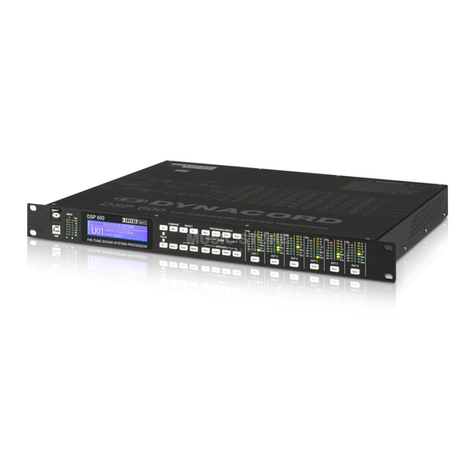
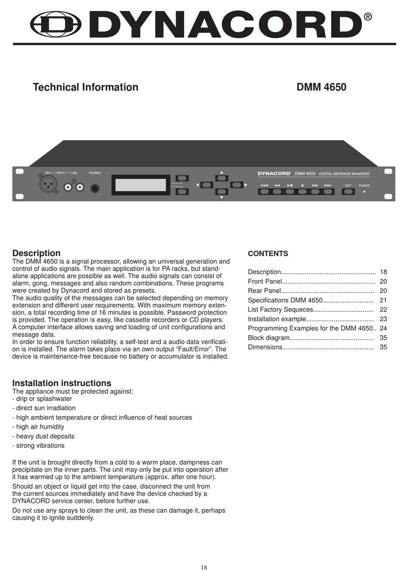
Dynacord DMM 4650 Quick start guide

Description
The DMM 4650 is a signal processor which allows for an universal generation and control of audio signals. Its main
purpose is the installation in electro-acoustic rack systems, but stand-alone applications are possible as well. The
audio signals can consist of alarm, gong, voice messages but also of random combinations of these sources. The pro-
grams were created by Dynacord (preset). Anyway, it is possible for the user (consulting company, etc.) to modify tho-
se programs and store them as user-programs. The audio input can be mixed with the DMM 4650 internally generated
audio signals (e.g. gong signals with announcements), or given out as priority at the audio output (programmable).
The audio quality of the messages can be selected, depending on memory extension and different user requirements.
With maximum memory extension, a total recording time of 16 minutes is possible. Password protection for various
operation levels is provided. For “EASY-USER”, the provided operation features are similar to those known from cas-
sette recorders or CD players. The control of the programs is performed via floating inputs and floating outputs provide
status messages. The priorities and functions of these lines can be programmed individually (Setup).Acomputer inter-
face facilitates saving and loading of the unit’s configuration and its message data.
In order to ensure functional reliability, self-surveillance and audio data verification are employed. The alarm is ignited
via internal fault-output while all warnings are logged. The DMM 4650 is maintenance-free since no serviceable parts,
batteries or accumulators are to be found inside the appliance.
DMM 4650 DIGITAL MESSAGE MANAGER
OWNER’S MANUAL

CONTENTS
INSTALLATION INSTRUCTIONS .................................................................... 5
FRONT PANEL ................................................................................................. 6
REAR PANEL ..................................................................................................... 7
USE OF THE DMM 4650 .................................................................................... 8
Audio functions ..................................................................................... 8
Control functions ................................................................................... 8
Sequence functions .............................................................................. 9
OPERATION OF THE DMM 4650 ...................................................................... 10
General ................................................................................................. 10
Stand-by mode ..................................................................................... 10
Password, user password .................................................................... 10
Password, entry, operation end ............................................................ 10
Priority function ..................................................................................... 10
Menu structure ..................................................................................... 11
Operation menu diagram ...................................................................... 11
MESSAGE .......................................................................................................... 12
General ................................................................................................. 12
Message number, preset ...................................................................... 12
Operation menu message .................................................................... 12
Soft key “edt” ........................................................................................ 13
Title ........................................................................................ 13
Priority ................................................................................... 13
Play all .................................................................................... 13
Release .................................................................................. 13
Free space ............................................................................. 13
Info ......................................................................................... 13
Checksum .............................................................................. 13
Delete .................................................................................... 13
Level adjustment, record level ............................................................. 14
Remote recording ................................................................................. 14
Audio quality, recording time ................................................................. 14
Message memory extension.................................................................. 14
Asterisk (*) after displayed running time................................................. 14
GONG ............................................................................................................... 15
General ................................................................................................ 15
Gong presets ....................................................................................... 15
Operation menu gong ........................................................................... 15
Load ........................................................................................ 15
Edit........................................................................................... 15
Title ........................................................................................ 15
Priority ................................................................................... 15
Save ................................................................................... 15
Liste of available gong parameters ...................................................... 16
ALARM ............................................................................................................... 17
General ................................................................................................. 17
Alarm presets ....................................................................................... 17
Operation menü alarm ......................................................................... 17
Load ....................................................................................... 17
Edit ........................................................................................ 17
Titel ......................................................................................... 17
Priority ................................................................................... 17
Save ................................................................................... 17
List of available alarm parameters ....................................................... 18
ANNOUNCEMENT.............................................................................................................. 20
General .............................................................................................................. 20
Operation menu announcement.......................................................................... 20
2

TRIGGER.......................................................................................................................... 21
General ............................................................................................................. 21
Operation menu trigger ..................................................................................... 21
Trigger detection ................................................................................................ 22
Examples trigger adjustments .......................................................................... 22
SEQUENCE .................................................................................................................... 23
General ............................................................................................................. 23
Sequence Presets ............................................................................................. 23
Operation menu sequence ................................................................................ 23
Load ................................................................................................... 23
Priority ............................................................................................... 23
Stop trigger........................................................................................... 23
Step list ............................................................................................... 23
Title ...................................................................................................... 24
Save..................................................................................................... 24
Sequence example ............................................................................................ 24
List of available step functions in a sequence ................................................... 25
SETTINGS ...................................................................................................................... 26
General ............................................................................................................. 26
Operation menu settings .................................................................................. 26
Contrast .............................................................................................. 26
Backlight ............................................................................................. 26
Headphones ....................................................................................... 26
Priority ............................................................................................... 26
Password ............................................................................................ 26
Outputs ............................................................................................... 26
Bypass ............................................................................................... 26
Sum gain ............................................................................................. 27
init DMM 4650 .................................................................................... 27
format Flash ....................................................................................... 27
Flash space ........................................................................................ 27
Software ............................................................................................. 27
Language ........................................................................................... 27
Backup ............................................................................................... 27
Restore ............................................................................................... 28
RS 232 ............................................................................................... 28
Clock .................................................................................................. 28
SELF-TEST .................................................................................................................... 29
General ............................................................................................................ 29
Operation menu self-test ................................................................................. 29
CONNECTIONS ............................................................................................................. 30
Control inputs and control outputs Port A - D ................................................... 30
General .............................................................................................. 30
Control levels and currents .............................................................................. 30
Inputs ................................................................................................. 30
Outputs .............................................................................................. 31
Installation example .......................................................................................... 31
Inputs ................................................................................................ 31
Outputs ............................................................................................. 31
Audio inputs and outputs .................................................................. 32
Remote, RS 232 connection, data backup ................................................... 33
General .............................................................................................. 33
Connection REMOTE/RS 232 ........................................................... 33
Interface settings ............................................................................... 33
Backup, Restore commands, priority ................................................ 33
List of REMOTE commands ............................................................. 34
Terminal programs .............................................................................. 35
3

4
FACTORY PRESETS ......................................................................................... 36
Factory presets, defaults ..................................................................... 36
List of trigger signals ........................................................................... 36
List of factory preset sequences ......................................................... 37
List of factory preset gong signals ........................................................ 45
List of factory preset alarm signals ....................................................... 46
APPENDIX ........................................................................................................ 47
Troubleshooting .................................................................................... 47
FAQ’s, hints ......................................................................................... 48
Examples for alarm texts ..................................................................... 50
Block diagram ..................................................................................... 51
Dimensions .......................................................................................... 52
Specifications ....................................................................................... 53

5
5
SAFETY COMPONENT ( MUST BE REPLACED BY ORIGINAL PART )
NOTE:
The lightning flash with arrowhead symbol, within an equilateral
triangle is intended to alert the user to the presence of
uninsulated „dangerous voltage“ within the product’s enclosure
that may be of sufficient magnitude to constitute a risk of
electric shock to persons.
The exclamation point within an equilateral triangle is intended
to alert the user to the presence of important operating
and maintance (servicing) instructions in the literature
accompanying the appliance.
1. Read these instructions.
2. Keep these instructions.
3. Heed all warnings.
4. Follow all instructions.
5. Do not use this apparatus near water.
6. Clean only with a dry cloth.
7. Do not block any ventilation openings. Install in accordance with the manufactures instructions.
8. Do not install near any heat sources such as radiators, heat registers, stoves, or other apparatus (including amplifiers) that produce
heat.
9. Do not defeat the safety purpose of the polarized or grounding-type plug. A polarized plug has two blades with one wider than the
other.Agrounding type plug has two blades and a third grounding prong. The wide blade or the third prong are provided for your safety.
If the provided plug does not fit into your outlet, consult an electrican for replacement of the obsolete outlet.
10. Protect the power cord from being walked on or pinched particularly at plugs, convenience receptacles, and the point where they exit
from the apparatus.
11. Only use attachments/accessories specified by the manufacturer.
12. Unplug this apparatus during lightning storms or when unused for long periods of time.
13. Refer all servicing to qualified service personnel. Servicing is required when the apparatus has been damaged in any way, such as
power-supply cord or plug is damaged, liquid has been spilled or objects have fallen into the apparatus, the apparatus has been
exposed to rain or moisture, does not operate normally, or has been dropped.
14. Do not expose this equipment to dripping or splashing and ensure that no objects filled with liquids, such as vases, are placed on the
equipment.
15. To completely disconnect this equipment from the AC Mains, disconnect the power supply cord plug from theAC receptacle.
16. The mains plug of the power supply cord shall remain readily operable.
CAUTION: These servicing instructions are for use by qualified personnel only. To reduce the risk of
electric shock, do not perform any servicing other than that ontained in the Operating
Instructions unless you are qualified to do so. Refer all servicing to qualified service personnel.
1. Security regulations as stated in the EN 60065 (VDE 0860 / IEC 65) and the CSA E65 - 94 have to be obeyed when
servicing the appliance.
2. Use of a mains separator transformer is mandatory during maintenance while the appliance is opened, needs to be operated and is
connected to the mains.
3. Switch off the power before retrofitting any extensions, changing the mains voltage or the output voltage.
4. The minimum distance between parts carrying mains voltage and any accessible metal piece (metal enclosure),
respectively between the mains poles has to be 3 mm and needs to be minded at all times. The minimum distance between parts
carrying mains voltage and any switches or breakers that are not connected to the mains (secondary parts) has to be 6 mm and needs
to be minded at all times.
5. Replacing special components that are marked in the circuit diagram using the security symbol (Note) is only permissible when using
original parts.
6. Altering the circuitry without prior consent or advice is not legitimate.
7. Any work security regulations that are applicable at the location where the appliance is being serviced have to be strictly obeyed. This
applies also to any regulations about the work place itself.
8. All instructions concerning the handling of MOS - circuits have to be observed.
IMPORTANT SERVICE INSTRUCTIONS
IMPORTANT SAFETY INSTRUCTIONS
WEEE Recycling/Disposal Instructions
The Wheelie Bin symbol found on the product or in the manual indicates that this product must not
be disposed of with other waste. It is in our category the manufacturer’s responsibility to properly
dispose of their waste electrical and electronic equipment (WEEE) at the end of its life. Due to
the differences in each EU country’s management of WEEE, please contact your local distributor.
We are committed to facilitate our own electronic-waste-management-system, for the free of
charge return of all EVI Audio GmbH products: Telex, Dynacord, Electro-Voice, Midas Consoles,
KlarkTeknik and RTS. Arrangements are made with the dealer where you purchased the equipment
from, for the returning of all unusable equipment at no cost, to the factory in Straubing, for
environmental protective disposal.

6
1. INPUT MIC
XLR-socket for the connection of a microphone when
recording a message. By using a short test-sample, the
level is automatically adjusted and the setting is saved.
This input can also be used for making announcements.
2. INPUT LINE
RCA-type sockets for the connection of stereo or mon-
aural audio signal sources (tape deck, CD player) when
recording a message. A wired in parallel 0dBu socket
on the rear panel is also provided. By using a short test-
sample, the level is automatically adjusted and the setting
is saved.
This input can also be used for making announcements.
3. PHONES
Stereo phone jack 1/4“ (6.3 mm) to pre-listen to mes-
sages, gong and alarm signals via headphones. Wired in
parallel, a 0dBu socket is provided on the rear panel.
4. Multi-function Display
Back-lit LC display, 2 lines with 16 characters, each.
The display lights up by pressing any key.
The display is dimmed whenever the EXIT-key gets
pressed or no key is pressed for at all within a short
while.
5. SOFT KEY
Depending on the selected operation mode, the soft keys
are used in various ways. The according function is indi-
cated on the display.
6. CURSOR
CURSOR-keys to control the cursor on the display and
for modifying data.
Frontpanel
7. RECORDER
Keys for …
TITLE skip back, REWIND, PLAY/STOP, REC, FAST
FORWARD, TITLE skip forward.
8. EXIT
Key for exiting the edit mode in order to prevent unautho-
rized operation. Each pressing of the key switches back
one menu stage.
9. POWER
The LED lights whenever the DMM 4650 is ready for
operation. In case the LED BLINKS you should contact a
DYNACORD service center.
PHONESMIC LINEINPUT
EXIT POWER
DMM 4650
123 456789
DIGITAL MESSAGE MANAGER

7
OUTPUT INPUT
MADE IN GERMANY
+-
24V
96
REMOTE
51 113
14 25
POR T A POR T B POR T C POR T D PRE-OUT REC-INP
113
14
113
14
113
14
25 25 25
DMM 4650 SER.NO.
121675
10 11 12 13 14* 15* 16 17 18 19
10. 24 V DC power supply
2 flat-pin plugs 1/4“ (6.3 mm) for connection to emergen-
cy power supply (battery) or other external power sour-
ces. Please mind the correct polarity (+-).
11. REMOTE
The 9-pole D-SUB connector “Remote-Control RS-232“ is
a serial computer interface for data transfer and service
functions.
PORT A-D
All inputs and outputs are provided in 2-pole floating de-
sign and isolated from the DMM 4650 circuitry and adja-
cent lines.
Each input is realized as an AC opto-coupler (AC floating
polarity).
Each output has a floating relay contact.
Each port connector (DB 25) has 4 inputs, 4 outputs, and
per port +24 V line and ground potential conductors.
By means of the 24 V DC voltage, it is possible to con-
nect external floating control keys as well as contacts
directly.
All inputs and outputs and their corresponding functions
can be freely assigned or a factory preset can be recalled
instead.
12. PORT A
4 control inputs and 4 trigger outputs
1 fault output (alarm on defect of the appliance)
1 ±24V DC, 90 mA power source
13. PORT B
Control inputs, trigger outputs and ±24 V DC
14. PORT C
Control inputs, trigger outputs and ±24 V DC
* optionally retrofitted
15. PORT D
Control inputs, trigger outputs and ±24 V DC
* optionally retrofitted
16. PRE-OUT
RCA-type socket, pre-listen
17. REC-INP
RCA-type socket, recording, announcement
18. OUTPUT
3-pole XLR-type connector (audio output) electronically
balanced (transformer can be retrofitted).
19. INPUT
3-pole XLR-type connector (audio input) electronically
balanced (transformer can be retrofitted).
Rearpanel
7

8
8
Use of the DMM 4650
The DMM 4650 can be used in both, incorporated in a rack shelf system or as stand-alone unit. The instal-
ler should automate the daily sequences by external control keys, sensors, contacts and the corresponding
unit settings. This applies for gongs, alarms, messages and their combinations, as well as for recordings of
variable announcements. This contributes to a considerable advantage in the ease of use since manually
operating the appliance is not necessary anymore.
Often used functions of the DMM 4650 are directly implemented as factory presets and can be utilized wit-
hout any additional programming effort. By editing the default values and storing them into a user preset a
customer-optimized configuration is quickly developed.
Audio function
The audio signals of the electro-acoustic sound reinforcement system are looped via INPUT and OUTPUT
to the power amplifier. The SUM control can be programmed for this stand-by position. In case of failure
a stand-by relay takes over the connection. When starting a sequence via control line, the desired audio
signal gets generated (DMM SIGNAL) and fed to the OUTPUT via the programmable DMM-control. The
controls (DMM, SUM) defined within the sequence determine, whether the two audio signals are merged or
the one gains priority over the other.
The MIC, LINE input is used for recording a message and can also be used for announcement purposes.
The headphones outputs PRE-LISTEN and PRE-OUT are for monitoring the DMM signals without actually
starting a transmission.
Control function
A maximum of 16 floating inputs are provided for integration into a sound reinforcement installation. Their
use and polarity can be freely programmed. A maximum of 16 floating relay contacts are provided to be
used as control outputs. The inputs and outputs are divided into 4 Ports (A, B, C, D,); where PortAalso
contains a fault contact.
Programmable Level
Programmable Level
*

9
9
Each of the 4 ports also supplies a power source in order to facilitate the connection of floating contacts.
The ground and earthing conditions are shown in the above diagram. The strict separation of control and
audio signals guarantees the trouble-free installation.
Sequence function
The following example shows in sequence the necessary steps from closing the contact of an external
switch to listening to the audio signal:
A switch is connected to one of the DMM 4650’s control inputs (A1 - D4). The desired input is selected in the
trigger menu. Logic level (high, low), delay, and function (dyn, stc, latch) can be set. The desired sequence
(Sxx) gets chosen here as well.
For this sequence, the actions of the DMM 4650 are programmed step by step. Standard sequences are
provided as factory presets. They can be modified as need arises and stored as user presets.
Example of a sequence: set output (lamp indicator), audio control SUM off, audio control DMM -3 dB, wait
for input release, after release start alarm, delay 10 sec. (alarm duration), end.
This sequence is entered line-by-line with special commands (list page 25) and - including name and priority
- stored as a preset. If an appliance uses unaltered functions on a regular basis, it is also possible to save
these sequences via the RS 232 interface.

OPERATING THE DMM 4650
General
All adjustments carried out at the appliance remain in memory even if the appliance is not connected to a po-
wer source (EPROM).Pressing the EXIT-key lets you step back and forth through the levels of the operation
menu tree (page 11). The stand-by mode is entered by pressing the EXIT-key when in the “main menu”.If no
key is pressed within a period longer than 5 minutes, the appliance enters the stand-by mode automatically
(except during recording and restore).
Stand-by
When the DMM 4650 is connected to a power source, the green POWER-LED lights, the display is dimmed,
and the relay outputs are set to their pre-programmed states according to the system’s configuration. This
stand-by status is remained until a control input starts a sequence. The display shows the sequence’s name
and number for the duration of the sequence. After completion of the sequence, the DMM 4650 re-enters
stand-by mode.The states of the control “outputs”, the audio relay “bypass”, and the “sum level” setting during
stand-by operation are set in the operation menu“System setup” (page 26).
Password
Password-protection prevents the DMM 4650 from unauthorized operation. Three distinct user levels are avai-
lable which can be accessed by entering the respective password. As factory defaults, “1111“ is programmed
for Level 1 (easy operation), ”2222“ for Level 2 and “3333“ for Level 3 (installer). Individual modification for
each user is possible. The menu tree diagram (page 11) shows which access is assigned to the respective
user level.
Password entry, operation end
Pressing any key on the DMM 4650’s front panel, “Password ?” appears on the display. Using the cursor keys
you have to enter a 4-digit number and confirm it with the menu key ok. After entering the correct 4-digit pass-
word, the display shows the number of your user level. Using the cursor keys you are able to select the desi-
red menu. The EXIT-key cancels the operation and the appliance is protected against unauthorized use.
Priority function
With the DMM 4650 provides the opportunity to set priorities from 0 to 99; where 99 represents the highest
priority level. Setting the priority level leads in different results.
The priority of a sequence is defined by its free programmable priority setting (menu “sequence” “priority”).
This determines, whether e.g. a fire alarm sequence cancels a gong control sequence. Not the control line
of an input, but the priority number of the triggered sequence determines its priority. With equal priorities, the
sequence that had been started first remains valid.
The selected user level states the priority for the operation on the appliance. User level 1 = priority no. 33,
user level 2 = priority no. 66, and user level 3 = priority no. 99. Modifying the default for lower user levels is
performed within the menu “System setup” “priority’”. The setting of the user priority controls, whether an ope-
rator gets interrupted by an important sequences (sequence priority).
Users are able to modify messages, gongs, and alarms and save them as user presets. Depending on the
actual user level, the programs are automatically provided with the corresponding user priority numbers (see
above). They are maintained for the case that the original preset’s priority is lower. In this way it is guaranteed
that user 1 cannot modify the presets of user 2. In order to allow access for other users, the priority allocation
can be modified downwards (lower priority) by the respective user before storing a preset(menu: “message >
priority“, gong“ > “priority”, “alarm“ > ”priority“)If recording a message via remote recording, the priority number
of the recording sequence is transferred to the message.
10

Passwort
Hauptmenue
Main-Menue
Alarm
Alarm
1
Gong
Gong
1
Sequenz
Sequence
2
Message
Message
1
Auslöser
Trigger
3
Durchsage
Announcement
1
$"EEinstellung
System-Setup
1
Selbsttest
Selftests
3
Kontrast
Contrast
1
Helligkeit
Backlight
1
Kopfhörer
Phones
1
Priorität
Priority
2
Passwort
Password
1
Software
Software
1
Sprache
Language
3
RS232
RS232
2
Uhr
Clock
1
Titel
title
1
Priorität
priority
1
Leerblocks
free space
1
Checksumme
checksum
3
löschen
delete
1
laden
load
1
Editor
edit
1
Titel
title
1
Priorität
priority
1
sichern
save
1
laden
load
1
Editor
edit
1
Titel
title
1
Priorität
priority
1
sichern
savel
1
laden
load
2
Priorität
priority
3
Stoppbedingung
stop-trigger
3
Schrittliste
step-list
2
Titel
title
2
sichern
save
3
1 = Easy use = User 1
2 = Normal use = User 1 +2
3 = Special use = User1+2+3
Ausgänge
Outputs
3
Bypass
Bypass
3
Summenpegel
Sum-Gain
3
init DMM 4650
init DMM 4650
3
format Flash
format Flash
3
Flash Platz
flash space
1
Backup
Backup
2
Restore
Restore
3
Play/record
edit
1
Play alle
play all
3
freigeben
release
3
Info
info
3
Abschwächer
Attenuator
3
bestätigen
confirm
3
11
Main menu
Annoucement
Setting
Brilliance
Use the cursor keys to
enter your password
Password?
**** ok
EXIT
EXIT
EXIT
Use the two cursor keys to
select the desired menu
*
self-test
Main menu
ok
Main menu
Clock ok
*
*
*
*
*
*
ok ok
ok
ok
Use the two cursor keys to
center and alter values
Main menu
Setting
Setting
Contrast
LCD-contrast
-10% norm
*
*
ô
ô
Menue tree structure

MESSAGE
General:
Messages are audio signals, stored in the DMM 4650 as information, alarm announcements or other
often used texts. Recording a message can be performed directly at the DMM 4650 or by means of
remote recording. Playback via sum output is achieved by starting a message (Mxx) within a suitable
sequence (see “Trigger”, “Sequence”).For test purposes the message can be listened to via the Pre-lis-
ten outputs using the recorder keys PLAY/STOP. The functions are similar to a cassette recorder, with
the difference that the audio data is saved digitally in maintenance-free flash memories. Depending on
individual needs, different audio qualities are selectable. The maximum recording time depends on the
selected audio quality and the installed memory (see table, page 14).A backup of all message audio
data is possible through analog recording (cassette deck, DAT recorder) or as a digital backup on a
computer via the remote interface (RS 232).
Message number,
Preset Up to 100 distinct messages (M00 to M99) including title, name, and priority can be saved.The
DMM 4650 is shipped without any pre-recorded messages, since - depending on individual user re-
quirements and custom applications – variations would be numerous. Some factory preset sequences
use M00, M01, and M02 (see list of preset sequences). Thus, they have to be recorded for incorporating
them in the respective applications. Some text examples are to be found at the end of this manual.
Operation menu “message”
Confirming the menu selection “message” by using the soft key “ok”, the number of the message ap-
pears in the display together with its title and playback time (hours : minutes . seconds). The DMM 4650
is now in the recording/playback mode and can be operated using the transport-keys as follows:
Note: This mode only allows playback via the PRE-listen/Phone outputs!
Title skip backwards, selects the previous actually recorded message. During playback the
selected message starts playing immediately.
Rewind, skips back one message, during playback fast rewind enables the user to listen to
a specific part several times.
Play/Stop starts or stops the playback of the selected message. Recording is stopped by
pressing the stop key.
Recording, pressing this key once switches the selected message into recording stand-
by. In case a previously recorded message exists, the question “delete?” is displayed and
leaving you the choice to record a new message with “Y=Yes” or cancel the command
with“N=No”. If you choose delete, the record key has to be pressed again after completi-
on of the procedure. If this message is not supposed to be deleted, you have to select an
empty location. The items “Recording type ”and “Recording level” are explained later. The
display now shows “record Mxx” and “pause” with a bargraph, indicating the current signal
level. Pressing the record key again starts the recording and “play time” replaces “pause”.
Pressing the Stop/Play-key terminates the recording.
Fast forward, skips to the next message, forwarding during playback enables the user to
listen to parts of a longer message.
Title skip forward, selects the next actually recorded message, during playback this next
message is immediately audible.
Using the cursor keys lets you select the previous or next message number.
Soft key “vl” accesses the volume setting dialog for the phone and pre-listen outputs using
the cursor keys.
Soft key “edt” accesses the menu level for title editing, etc. (see following paragraph).
12

Soft key “edt”
Using the “edt” key in playback mode provides the opportunity to edit and manage your message
structure. The keys are used to select the following menu items.
Title
Confirming “Title” with the soft key “ok” the selected message’s current name appears on the display.
Using the cursor keys lets you enter a name which can consist of up to 8 characters. The soft keys
“A-a” are used to toggle between between the upper and the lower letter case while “spc” inserts a
blank. After pressing “EXIT” (one menu level down) the question “store y, n” appears, in order to pre-
vent any inadvertent alteration of the name.
Priority
Confirming “Priority” with the soft key “ok”, the priority number of the selected message appears on
the display and, by using the cursor keys, providing the user with the possibility to alter the number
from 00 up to the his/her priority level. A higher priority prevents unauthorized alteration of this preset
by users with lower priority. After pressing “EXIT” (one menu level down) you have to choose on the
appearance of the question “store y, n”, whether you want to make your changes permanent.
Play all
Confirming “Play all” with the soft key “ok”, the name of the first message gets displayed. Using the
PLAY/STOP-key lets you start or stop the playback of all recorded messages. Mostly, this menu item
serves for transferring all recorded messages onto an analog audio tape deck or DAT recorder via
the phone/pre-listen outputs.
Release
Confirming “Release” with the soft key “ok”, the display shows that the search for lost blocks in the
flash memory (sound memory) has been engaged. Whenever such blocks are found, the memory
structure gets repaired which is also indicated on the display. This menu’s operation is used to re-
lease memory that has been mistakenly reserved.
Free space
Confirming “Free space ” with the soft key “ok”, the number of available flash memory chips and the
overall free sound memory capacity are displayed in %.
Info
Confirming “Info” with the soft key “ok”, shows the audio quality setting and the used space for the
previously selected message.
Confirm
The audio data of a message is constantly monitored. In case an inaccurate data structure (see also
self-surveillance page 29) is detected, the corresponding message is marked with an asterisk (*).
Anyway, if the erroneous data does not affect the audible result of the sound reproduction, “confir-
ming” with the soft key “ok” omits the marking (*). From now on, the actual data is utilized as test pat-
tern and you are given the possibility to acknowledge the fault indication (Power-LED blinks) within
the menu “self-test” (page 29).
Check sum
Confirming “Check sum” with the soft key “ok”, the check sum of the previously selected message
appears on the display. In case of fault, this value is used as a reference for erroneous messages.
Delete
Confirming “delete” with the soft key “ok”, shows the question “delete?” on the display. Using the soft
keys “y=yes, n=no” lets you erase the previously selected message.
13

Recording level
An integrated, electronic control automatically adjusts the input sensitivity of the DMM 4650’s (Mic,
Line, Rec. Inp) inputs. This level setting remains unchanged, until the question “Select new recording
level?” is answered by using the soft key “y=yes” before starting a new recording. By using a short test
signal marks the new setting of the control which is automatically stored. Pressing the soft key “ok”
exits the recording level menu.
Adjusting the recording level only becomes necessary when the connected signal source is changed
or major level changes occur.
Remote recording
It is possible to activate a recording via one of the control inputs (ports A .. D). An example given in the
list of factory sequences (S29, S30) on the pages 40-41. The message defined within the sequence
is automatically erased before the new recording starts. The example employs an indication lamp for
start recording (= deleting end) and the maximum recording time is set to 10 seconds.
Adjusting the recording level corresponds to the description in the previous paragraph. The message’s
audio quality setting stays unaltered as well. The priority number of the sequence gets copied to the
priority of the message.
Audio quality, recording duration
Prior to recording a message, “recording type” is shown on the display. The cursor keys are used to
alter the audio cutoff frequency (16 kHz, 8 kHz, 4 kHz) and the signal quality (CD = 16 bit linear, long
= 8 bit, μ-Law). The factory default setting is “8 kHz long” for all messages. The newly set audio quality
is maintained and individual adjustment for each message is possible.
Table for recording time (minutes) versus audio quality and installed sound memory extension (NR
90205).
Accuracy CD long*
bandwidth 4 kHz 8 kHz 16 kHz 4 kHz 8 kHz 16 kHz
without NR 90205 2 min 1min 0,5 min 4 min 2 min 1 min
1x NR 90205 4 min 2 min 1 min 8 min 4 min 2 min
2x NR 90205 6 min 3 min 1,5 min 12 min 6 min 3 min
3x NR 902058 8 min 4 min 2 min 16 min 8 min 4 min
* The specified times for the“long“ recording mode are minimum values since the active data reduction
recognizes pauses in the audio signal. Pauses are defined as passages where the signal level drops
-70 dBu below full modulation.
Message memory extension
It is possible to extend the sound memory capacity of the appliance by incorporating up to three addi-
tional plug-in boards (extension kit NR 90205). The corresponding recording times are specified in the
table above. The flash memories have to be formatted after insertion (see menu “system setup” >“for-
mat flash”).
Asterisk (*) behind message duration
An asterisk * behind the message recording time display signals that the corresponding data has been
corupted. The error is shown by the blinking Power-LED. In case you decide that the audio quality is
sufficient, after listening to the recording, you have to enter the menu “confirming” (page 13) to delete
the *-sign. If the result is not tolerable, the only solution is re-recording the message. To omit the blin-
king Power-LED you have to acknowledge error no. 14 in the “self-test” menu (page 29).
14

GONG
General:
Gong Presets are audio signals that can be started within a sequence. Order and parameters of a gong
sequence can be edited. For test purposes the sound can be started in the “gong >editor” menu by use
of the PLAY/STOP keys. It is audible via the Pre-Listen outputs.
Gong Presets
20 freely programmable presets (user preset) are available; from G00 - G19. Starting with G20 and going
to G26 factory preset gong sequences are programmed. The corresponding functions are explained in
the table on page 45. Erasing the factory presets is not possible. Creating your own gong sequence is
easiest accomplished by modifying an existing, possibly similar gong (user or factory preset) and storing
it under a new number together with its new title and priority.
Operation menu gong
Confirming the menu selection “gong” with the soft key “ok”, the cursor keys < >allow selecting the follo-
wing sub menus.
Load
Confirming “load” with the soft key “ok”, “Gxx ‘Title ‘and the soft keys ”yes, no“ appear on the display.
Using the cursor keys the gong number xx is modified while the corresponding name is being displayed.
“y” lets you load the selected gong into memory and modification is performed in the “editor” menu.
Editor
The “editor” menu allows modification of gong sequences, envelopes, repetition amounts and several
other parameters (see parameter listing). Testing the gong’s sound properties is possible by starting
the gong sequence, using the PLAY/STOP key. The audio signal is presented at the pre-listen outputs.
Parameter modifications are audible after performing a restart. Pressing the RECORD key stops the
gong.After pressing the “EXIT” key (previous menu level), the question “store yes, no?” appears on the
display. Acknowledging this question lets you save your new settings in a user preset.
Title
Confirming “Title” with the soft key “ok”, the name of the currently loaded gong sequence appears on
the display. Using the cursor keys you are able to enter a new name that consists of up to 8 characters.
The soft keys “A-a” are used to shift between the upper and the lower character case while “spc” inserts
a blank character. After pressing the “EXIT” key (previous menu level), the question “store yes, no?” ap-
pears on the display. Acknowledging this question lets you save your new settings in a user preset.
Priority
Confirming “Priority” with the soft key “ok”, the priority number of the selected gong preset gets display-
ed. Using the cursor keys, the priority number can be set starting from 00 up to the user priority. A higher
priority protects against unauthorized alteration of this preset by users with lower priority level. All factory
presets are provided with a priority of 00, because they cannot be overwritten, anyway. This offers any
user the possibility to use them as prototype sequences.After pressing the “EXIT” key (one menu level
down), the question “store yes, no?” appears on the display. Acknowledging this question lets you save
your new settings in a user preset.
Save
Confirming “save” with the soft key “ok”, the currently selected gong number gets displayed. Using the
cursor keys, the desired gong number can be entered. Storing a preset has to be confirmed with the soft
key “y = yes”. With“save” all modifications in the above mentioned menu items are saved into the selec-
ted user preset. Thus, individually saving the parameters is not necessary, since they remain in memory
until another gong is being loaded.
15

List of available gong parameters
Type four-stroke, three-stroke
bar1: first gong stroke, A highest sound, B, C, to D deepest sound
attack1: attack rate from 00ms (hard) to 99ms (soft)
release1: fading sound from XXL (long, several seconds.), XL, L, M, S, XS, XXS (short, approx. 1sec)
start 2: start delay of the second gong stroke in seconds. (min 00.0s, max 99.9s)
bar2: second gong stroke, A highest sound, B, C, to D deepest sound
attack2: attack rate from 00ms (hard) to 99ms (soft)
release2: fading sound from XXL (long, several seconds.), XL, L, M, S, XS, XXS (short, approx. 1sec)
start 3: start delay between second and third gong stroke in seconds. (min 00.0s, max 99.9s)
bar3: third gong stroke, A highest sound, B, C, to D deepest sound
attack3: attack rate from 00ms (hard) to 99ms (soft)
release3: fading sound from XXL (long, several seconds.), XL, L, M, S, XS, XXS (short, approx. 1sec)
start 4: start delay between third and fourth gong stroke in seconds. (min 00.0s, max 99.9s)
bar4: fourth gong stroke, A highest sound, B, C, to D deepest sound
attack4: attack rate from 00ms (hard) to 99ms (soft)
release4: fading sound from XXL (long, several seconds.), XL, L, M, S, XS, XXS (short, approx. 1sec)
Type two-stroke, one-stroke
bar1: first gong stroke, A highest sound, B, C, to D deepest sound
attack1: attack rate from 00ms (hard) to 99ms (soft)
release1: fading sound from XXL (long, several seconds.), XL, L, M, S, XS, XXS (short, approx. 1sec)
start 2: start delay of the second gong stroke in seconds. (min 00.0s, max 99.9s)
bar2: second gong stroke, A highest sound, B, C, to D deepest sound
attack2: attack rate from 00ms (hard) to 99ms (soft)
release2: fading sound from XXL (long, several seconds.), XL, L, M, S, XS, XXS (short, approx. 1sec)
repetition: number of repetitions of the gong sequence (min 1x, max 9999x), 0000 corresponds to
infinite repetition.
rep-del: time between two gong sequences in seconds (min 00.1s, max 99.9s).
Remarks regarding parameter setting:
Although the above mentioned parameters are extensively variable, the gained results not always represent
a good sound. E. g.: attacks for low frequency bar strokes are acoustically quite different from the gongA
sound.
Since a maximum of 2 gong strokes can be simultaneously processed, starting the third gong too early will
abruptly end the first one and lead to unpleasant sound cut-off knacks. Effects like these resulting from ex-
treme parameter settings are of physical reason and should be optimized by listening tests, first.
16

ALARM
General:
Alarms are audio signals that can be started within a sequence. The alarms are square wave forms pro-
viding the possibility for various parameters to be adjusted. For test purposes, it is possible to start the
alarms signals in the “alarm editor” menu using the PLAY/STOP key. They are present on the pre-listen
outputs.
Alarm Presets
20 freely programmable presets (user presets) are available; from A00 to A19. The factory presets are
pre-programmed on the preset numbers A20 - A34. The corresponding functions are explained in the ta-
ble on page 46. Erasing these presets is not possible. In order to create your own alarm preset, modifying
an existing, possibly similar alarm (user or factory preset) and storing it under a new number together with
its new title and priority, is the easiest way to accomplish this task.
Operation menu alarm
Confirming the menu selection “Alarm” with the soft key “ok” lets you select the following sub menus
using the cursor < > keys .
Load
Confirming “load” with the soft key “ok”, Axx ‘Title’ and the soft keys “yes, no” appear on the display. Using
the cursor keys lets you edit the alarm number xx while the corresponding name is displayed. “Y” loads
the selected alarm into memory while further editing is performed in the “editor” menu.
Editor
The menu “editor” allows modification of audio frequencies, envelopes, duty-factors and several other
parameters (see parameter listing). Testing the alarm’s sound properties is possible by starting the alarm
sequence using the PLAY/STOP key. The sound is presented via the pre-listen outputs. Parameter mo-
difications are audible after performing a restart. The RECORD-key stops the alarm.After pressing the
“EXIT” key (previous menu level), the question “store yes, no?” appears on the display. Acknowledging
this question lets you save your new settings in a user preset.
Title
Confirming “Title” with the soft key “ok”, the name of the currently loaded alarm is displayed. Using the
cursor keys lets you enter a name of up to 8 characters. The soft keys “A-a” shifts between the upper and
the lower character case while “spc” inserts a blank character.After pressing the “EXIT” key (previous
menu level), the question “store yes, no?” appears on the display. Acknowledging this question lets you
save your new settings in a user preset.
Priority
Confirming “Priority” with the soft key “ok”, the priority number of the selected alarm preset appears on
the display. Using the cursor keys, the priority number can be set starting from 00 up to the user priority. A
higher priority protects against unauthorized alteration of this preset by users with lower priority level. All
factory presets are provided with a priority of 00, because they cannot be overwritten, anyway. This offers
any user the possibility to use them as prototype sequences.After pressing the “EXIT” key (one menu
level down), the question “store yes, no?” appears on the display. Acknowledging this question lets you
save your new settings in a user preset.
Save
Confirming “save” with the soft key “ok”, the currently selected alarm number is displayed. Using the cur-
sor keys, you are able to enter the number of the desired alarm. Storing a preset has to be confirmed with
the soft key “y = yes”. With“save”, all modifications in the above mentioned menu items are saved into the
selected user preset. Thus, individually saving the parameters is not necessary, since they remain in me-
mory until another gong is being loaded.
17

18
List of available alarm parameters
Typ Uni-sweep
frequency1: pitch at sound-start in Hz (min 40Hz, max 9999Hz) is swept until frequency2 is reached.
frequency2: pitch at sound-stop in Hz (min 40Hz, max 9999Hz).
time: duration of the sweep - Freq1 to Freq2 - in seconds., (min 0.01s, max 99.99s).
ratio: duty-cycle of the square wave in percent, (min 1%, max 50%)
repeat: number of repetitions of the sweep Freq1. > Freq2 (min 1x, max 9999x).
0000 corresponds to infinite repetition.
Values in parenthesis ( ), example DIN alarm, A20
Type Bi-sweep
frequency1: pitch at sound-start in Hz (min 40Hz, max 9999 Hz) is swept until frequency2 is reached.
frequency2: reverse frequency of the sound in Hz (min 40Hz, max 9999Hz) is swept until frequency1
is reached.
time: sweep duration from freq1 to inversion point in sec., (min 0.01s, max 99.99s).
The duration of the sweep freq1>inversion point >freq1 is symmetrical.
ratio: duty-cycle of the square wave in percent, (min 1%, max 50%)
repeat: number of repetitions of the sweep Freq1.>inversion point (min 1x, max 9999x).
0000 corresponds to infinite repetition.
Values in parenthesis ( ), example siren, A22
Type continuous sound
frequency: pitch of the sound in Hz (min 40Hz, max 9999Hz)
ratio: duty-cycle of the square wave in percent, (min 1%, max 50%)
time: duration in sec., (min 0.01s, max 99.99s). 0.00s corresponds to infinite duration.
Values in parenthesis ( ), example BZB all clear signal, A25
18

19
19
Typ Jump-sound
frequency1: pitch at sound-start in Hz (min 40Hz, max 9999Hz) jumps after time1 to frequency2
time1: duration for which freq1 is heard in sec., (min 0.01s, max 99.99s).
frequency2: pitch of the sound in Hz (min 40Hz, max 9999Hz) jumps after time2 to frequency1
time2: duration for which freq2 is heard in sec., (min 0.01s, max 99.99s).
ratio: duty-cycle of the square wave in percent, (min 1%, max 50%)
repeat: number of repetitions of one frequency (min 1x, max 9999x).
0000 corresponds to infinite repetition.
Values in parenthesis ( ), example Post, A23
Typ burst
Frequency: pitch of the sound in Hz (min 40Hz, max 9999Hz)
on-time: duration for which the sound is heard in sec., (min 00.01s, max 99.99s).
off-time: duration of the pause in sec., (min 00.01s, max 99.99s).
Ratio: duty-cycle of the square wave in percent, (min. 1%, max. 50%)
repeat: number of repetitions of the sound (min 1x, max 9999x).
0000 corresponds to infinite repetition.
Values in parenthesis (), example ship2, A31

Announcement
General:
Using the announcement function provides the possibility to assign incoming audio signals from the re-
cording inputs (Mic, line, Rec-Inp) directly to the sum output. Especially in stand-alone applications this
option is particularly useful, since it will possibly save one microphone amplifier. Starting the function is
either performed in the DMM 4650’s operation menu or remotely controlled via a control line. For external
operation a sequence is provided as factory preset S32 (page 42) which is easily adapted according to
individual requirements.
Operation menu announcement
Confirming the menu selection “announcement” with the soft key “ok”, “select new input level?” and the
soft keys “yes, no” are displayed. Adjusting the electronic input level control is performed here. After re-
cording a short test signal, the control’s new setting is automatically stored and stays. This value is inde-
pendent of the recording level in Massage recording. Pressing the soft key “ok” cancels the level adjust-
ment menu and the DMM 4650 returns into announcement mode.
The display shows the message “Announcement” and a bargraph for optical control of the correct input
level setting. The soft key “vl” allows modifying the pre-listen outputs’ volume setting while “end” closes
the announcement function.
Setting the recording level a new is required only when the connected signal source is changed or any
other large scale alterations of the input level take place.
20
Other manuals for DMM 4650
2
Table of contents
Other Dynacord Computer Hardware manuals
Popular Computer Hardware manuals by other brands

Corsair
Corsair Hydro H60 Quick start quide

Multitech
Multitech MTDOT-915 Series Developer's guide

Ice-Tech
Ice-Tech POD-51EH-C541U-12 operating instructions

KEPCO
KEPCO SUPERtrol II Startup guide

ARTESYN EMBEDDED TECHNOLOGIES
ARTESYN EMBEDDED TECHNOLOGIES SharpMedia PCIE-8120 Assembly, Installation and Use

Black Box
Black Box URP48 quick start guide