DynaGen Tough Series User manual

Manual Revision: 7.0.0
Min. FW Revision: 1.90.20
Date Released: 2019-07-24
© 2019 DynaGen Technologies Inc
TR100-E User Manual

TR100-E User Manual
© 2019 DynaGen Technologies Inc
Table of Contents
3
1Introduction
............................................................................................................................................................................... 3
Limitations1.1
4
2Wiring and Setup
............................................................................................................................................................................... 5
Typical Wiring Diagram2.1
6
3Using the Remote
............................................................................................................................................................................... 6
Power Up3.1
............................................................................................................................................................................... 7
Failure Shutdown3.2
............................................................................................................................................................................... 8
Front Panel Menu3.3
....................................................................................................................................................................... 8Operator Setup
3.3.1
....................................................................................................................................................................... 9Device Info
3.3.2
....................................................................................................................................................................... 9Adjusting Settings
3.3.3
............................................................................................................................................................................... 10
Starting and Stopping3.4
............................................................................................................................................................................... 11
Parameter Display3.5
............................................................................................................................................................................... 11
Speed Control3.6

2
© 2019 DynaGen Technologies IncTOUGH Series Manual
TR100-E User Guide
This is the user manual for the TR100-E, the Dynagen remote panel that w orks w ith the TE350 and TE410 controllers.

Introduction 3
© 2019 DynaGen Technologies IncTOUGH Series Manual
1Introduction
The TR100-E is a J1939 remote panel for use w ith the TE350 and TE410. In a J1939 netw ork there can be one local engine
controller (TE350 or TE410) paired w ith an unlimited number of remotes (recommend limiting to five remotes).
The remote mimics w hat is displayed on the controller (see limitations below ).
1.1 Limitations
The remote panel cannot communicate w ith more than one local controller and there can only be one local controller on a
single J1939 netw ork.
There are restrictions the remote panel has compared to w hat can be done locally on the controller:
1. The countdow n timers (e.g. delay to start, preheat, cranking, crank rest, w arm-up, ...) are not displayed on the remote.
2. The log cannot be accessed from the remote panel.
3. The aftertreatment (e.g. DPF) menu is not displayed on the remote panel. A DPF/DEF cannot be initiated from the remote
panel.
4. No I/O on the remote panel is supported such as sw itched inputs, sw itched outputs, analog inputs, or modbus (RS485)
communications.
5. The date and time on the remote must be programmed manually. It is not updated over J1939. All custom text (if
applicable) must be programmed to the remote using the RapidCore Configuration softw are.

Wiring and Setup 4
© 2019 DynaGen Technologies IncTOUGH Series Manual
2Wiring and Setup
Please follow the below guidelines w hen installing the remote panel.
Wiring
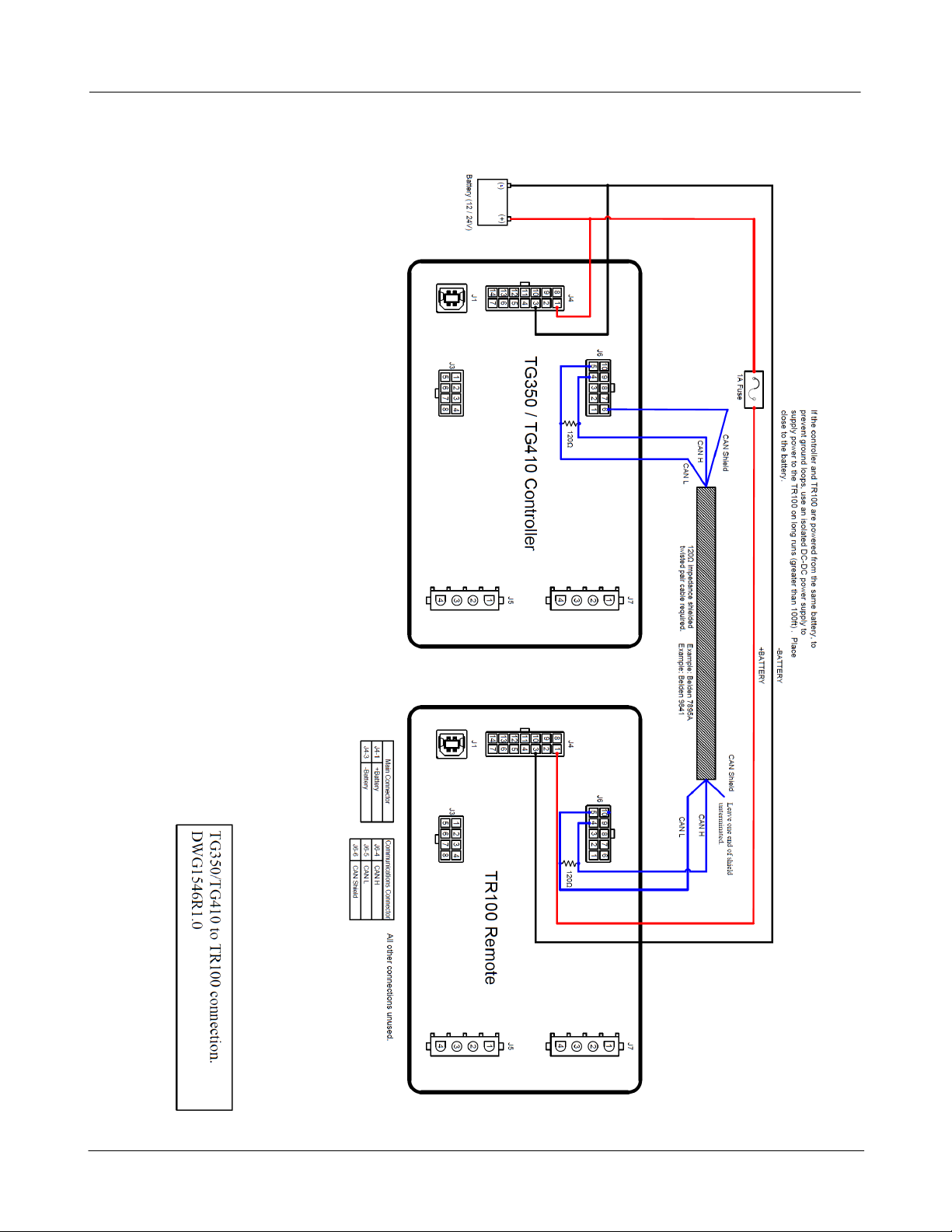
1. The maximum J1939 (CAN) cable distance is 40m (131.2ft). Tw isted pair or shielded tw isted pair cable must be used.
See J1939 standards J1939-11 for tw isted shield pair requirements or J1939-15 for tw isted pair (unshielded)
requirements. In brief, the cable must have a characteristic impedance of 120Ohms terminated at each end by 120Ohm
resistors. Note: cable impedance is not the same as the resistance of the cable.
2. The remote panel must be provided w ith pow er and ground connections.
TR100-E Setup
1. Dow nload the TR100-E firmw are from w w w .dynagen.com/support and unzip it to the desktop.
2. Using RapidCore program this firmw are into a TE350 or TE410 to convert it into a TR100-E.
Local TE350 / TE410 Setup
The remote needs access to certain parameters over the CAN J1939 bus. To do this follow these steps:
1. Using RapidCore read the settings from the local controller. A new settings tab w ill open. Go to that settings tab.
2. Under Communications > J1939 Bus > Broadcast Over J1939:
a. In the case of a mechanical engine these must be broadcasted by the local controller. Enable Engine Speed, Engine
Temperature, Oil Pressure, and Engine Hours.
b. In the case of an electronic engine some parameters are already broadcasted by the ECM and should not be sent by
the controller. Disable Engine Speed, Engine Temperature, Oil Pressure, or Engine Hours as these parameters are
send by the engine ECM. They should be hidden by default by RapidCore.
3. It is recommended to set "DTC Warning Broadcast Mode" to "Multiple Warning".
4. Enable Battery Voltage.
5. Enable AC Sensing and Fuel Level if applicable to your application.

Wiring and Setup 5
© 2019 DynaGen Technologies IncTOUGH Series Manual
2.1 Typical Wiring Diagram

Using the Remote 6
© 2019 DynaGen Technologies IncTOUGH Series Manual
3Using the Remote Panel
This section discusses how to use the remote.
Using the Menu System
Task
Description
Entering Menu
When in the OFF mode, press the enter button to bring up the menu.
Navigating Menu
Once in the menu, use the up and dow n arrow s to navigate. Pressing enter w ill move you
into that menu.
Change a Setting
Scroll to the desired value and press enter to select. A check mark should appear beside
that item. Press enter again to save the setting and return to the previous screen.
Scroll Parameters
When in Auto or Running mode, pressing the up and dow n arrow s w ill scroll through the
parameter pages.
Lock Screen
When in Auto or Running mode, the screen can be locked to a certain parameter page by
pressing Auto and unlocked by pressing Auto again.
Events History
Once in the menu, select Events History to view the most recent controller event. Use the
up and dow n arrow s to navigate to other events. The controller can store up to 150 events.
If more than 150 events occur, the oldest event is deleted to make room for the next event.
Front Panel Items
Item
Name
Description
Off Button
Used for turning off the engine or exiting out of Auto mode. This is not
intended to function as an Emergency Stop as there are conditions in
w hich it w ill not shut dow n the engine. See the OFF Button Function
section for more information.
Auto Button
Used for placing the controller into AUTO mode or locking the LCD screen
w hen view ing parameters. Once in AUTO mode, the controller w aits for
a start command to be received.
Run Button
Used to start the engine manually. The Off button must be used to shut
dow n the engine if it has been started using the front panel.
Up/Speed Increment
Button
Used for moving around in the menu, changing a setting's value, or
incrementing the engine speed in manual mode.
Scroll/Enter Button
Used for entering the menu system, accepting settings, or changing the
currently displayed parameter page.
Dow n/Speed
Decrement Button
Used for moving around in the menu, changing a setting's value, or
decrementing engine speed in manual mode.
Engine LED
Green = Engine running w ith no issues
Amber = Engine running w ith w arnings
Red = Engine shut dow n on failure
3.1 Power Up
Whenever the remote panel is pow ered up it w ill attempt to register w ith the local controller. This happens on every pow er
up.
Registration is a pairing process that establishes a communication link. Once established the remote panel and local controller
can communicate w ith each other.

Using the Remote 7
© 2019 DynaGen Technologies IncTOUGH Series Manual
If the remote panel is not registered and also cannot communicate w ith the local controller it w ill display the follow ing
message.
Check the w iring betw een the local controller and the remote panel.
Once the remote is registered it w ill display one of the follow ing screens depending on if the controller is in the OFF or AUTO
modes.
OFF AUTO
The remote cannot start the controller w hen it is in the OFF mode. This is to prevent accidental starts w hen the engine or
generator is being w orked on. If the controller is in AUTO then starting from the remote is permitted and the screen notifies
you of such.
If the remote could not register w ith the local controller the below screen is displayed.
Note that the remote is setup to w ork w ith certain systems only. It may not w ork w ith every TE350 or TE410 system. Check
w ith your OEM for assistance.
If communication w ith the controller is lost the remote w ill display the follow ing screen:
3.2 Failure Shutdown
If the local controller has shutdow n due to a failure the follow ing screen w ill be displayed on the remote panel.

Using the Remote 8
© 2019 DynaGen Technologies IncTOUGH Series Manual
The time, date, and reason for the failure w ill be displayed on the screen. To reset the failure press and hold off until the
controller goes back to the OFF state. Then release the OFF button. The remote w ill do a reset and the screen w ill flicker.
This is normal.
This is the screen that w ill be displayed w hen the controller is in the OFF mode after the failure has been reset.
3.3 Front Panel Menu
There are several settings the operator can change in the remote. The menu can only be accessed w hen the local controller
is in the OFF or AUTO modes. By pressing the Enter button the menu can be accessed.
The follow ing screen show s the main menu of the menu system. To exit the menu system at any time press and hold OFF
until you exit the menu.
The cursor is the solid bar. Press the up and dow n keys to move the curser up and dow n. Moving the cursor to Back and
pressing enter w ill exit the menu (or take you to the previous menu). "Operator Setup" and "Device Info." are sub-menus as
indicated by the right pointing arrow s. Scrolling dow n and pressing enter on one of them w ill take you to that submenu.
3.3.1 Operator Setup
The Operator Setup menu contains the follow ing items (The items in bold are submenus.).
Name
Range
Description
Lamp Test
Function
Performs a lamp test.
Display
Sub menu
Contains settings that control the screen and parameter
display behavior.
Date/Time
Sub menu
Date and time settings.
Operator Setup

Using the Remote 9
© 2019 DynaGen Technologies IncTOUGH Series Manual
The Display menu contains the follow ing items.
Name
Range
Description
LCD Reverse
Function
Reverses the screen. Black Text w ith w hite background or
w hite text w ith black background.
LCD Contrast
5 to 95% in 5%
increments (Default:
50%)
Adjusts the screen contrast.
Page Scroll
1 to 10s (Default: 5s)
Adjusts the time each parameter screen is displayed in RUN.
Message Pop-up
1 to 10s (Default: 5s)
Adjusts the amount of time a message (event or w arning) is
displayed on the second line of the display in RUN.
LCD Backlight
10 to 600s in 1s
increments. (Default:
600s)
Adjusts the time the LCD backlighting remains on after no key
presses. In RUN mode the back-light is on all the time.
Display
The Date/Time menu contains the follow ing items.
Name
Range
Description
Date Change
Sub menu
Day, month, and year settings.
Time Change
Sub menu
Hour, minute, and second settings
Daylight Savings
Disable/Enable
If enabled automatically adjusts the time for daylight savings.
This is valid for North American only.
Date/Time
3.3.2 Device Info
Selecting Device Info displays information about the TR100-E.
HV is the hardw are version. SV is the softw are version. SN is the serial number.
3.3.3 Adjusting Settings
In the menu system there are three types of menu screens used to adjust parameters.
(1) Select from a list of items.
An example of this type of setting is the Daylight Savings parameter in the Operator Setup > Date/Time menu.
Press up or dow n to scroll to the desired value. Press enter once to check the value. Press enter again to exit the menu. If
you only w anted to see w hat a setting w as set to and not change anything just scroll dow n to the checkmark and press
enter to exit the menu.

Using the Remote 10
© 2019 DynaGen Technologies IncTOUGH Series Manual
(2) Numeric Adjustment.
An example of this type of setting is the LCD Contrast parameter in the Operator Setup > Display menu.
Press up and dow n to change the setting. Press enter to select the change. A checkmark w ill be displayed. Pressing enter
w ill checkmark displayed w ill stored value and exit the menu.
(3) Multiple Numeric Adjustments.
An example of this type of setting is the time parameters in the Operator Setup > Date/Time > Time Change menu.
Press up and dow n to scroll to the desired parameter you w ish to change and press enter. The parameter value w ill be
selected. Press up and dow n to change the parameter. When finished press enter. The w hole parameter w ill be selected.
As before press up or dow n to scroll to the next parameter or back to exit the menu.
3.4 Starting and Stopping
The remote panel cannot start the generator if the local controller is in the OFF mode. This is a safety feature. When the
local controller is in the OFF mode the remote controller w ill display "System Off, Start Disabled".
Starting w ith the remote panel can only be accomplished w hen the local controller is in the AUTO mode; you must go to the
local controller and put it in AUTO if the local controller is in the OFF mode. When in AUTO mode the remote w ill display
"System Ready, Waiting to Start". Pressing the Run button on the remote panel w ill start the controller.
When in RUN mode pressing the Off button on the remote w ill shutdow n the controller. If the local controller w as started via
its front panel Run button then you must hold dow n the Off button on the remote panel for at least 3s -- this is referred to as
the forced off feature. It is to discourage remote users from overriding users that started the controller locally.
For installations w ith cooldow n delay, the remote panel cannot be used to cancel cooldow n and reenter the RUN mode.

Using the Remote 11
© 2019 DynaGen Technologies IncTOUGH Series Manual
3.5 Parameter Display
The remote panel does not display parameters that are disabled or that are set to a sw itch. If you don't see a particular
parameter on the remote panel display check if it is enabled on the local controller.
3.6 Speed Control
Manual Speed Control
If a manual start w as performed the user can increase/decrease the engine speed w ith the Up (Rabbit) and Dow n (Turtle)
buttons. On a manual start speed can be control either from idle or goal speed depending on how the local controller w as
programmed.
Automatic Speed Control
The local controller may automatically start due to a float auto start condition. If float auto start is enabled in the controller
then a special tank page w ill be displayed in Auto and Run mode show ing the position of the floats. Also a tank symbol might
be displayed next to the float tank display show ing the level of the tank. Engine speed is also show n on this page.
Other manuals for Tough Series
2
This manual suits for next models
2
Table of contents
Popular Control Panel manuals by other brands

EMS
EMS FirePoint System 5000 Communications guide

BLUGUARD
BLUGUARD SmartBus P900-TI6N user manual

See Water
See Water Oil Smart OSD3P-30 Series Installation and operation manual

BFT
BFT SHYRA AC F SL installation manual

Anilam
Anilam 5000M Training guide

Lift Tech Marine
Lift Tech Marine HYDRAULIC quick start guide