Note
To avoid damaging the device as a result of a voltage overshoot when switching
on, please observe the following:
Power supply is only permitted with round cables; do not use single wires.
To avoid voltage overshoots when connecting to low impedance supplies,
please pay attention to the lower inductance of the supply cable.
To ensure optimum attenuation of the voltage overshoot, the supply cable
should not be of too low an impedance. Festo therefore recommends a cross
section of 1.0 or 1.5 mm²
Observe the maximum load capacity of the cable.
Safeguard the supply cable appropriately. Do not exceed values in data
sheets. Only use regulated power supply units. First establish the secondary-
side connection, then switch on the power supply unit on the primary side. Do
not connect to sources when powered.
Note
For general protection of the device, and to avoid overloading the GND pins of
the interfaces in particular, please observe the following:
Do not connect any outputs in parallel.
Do not feed any voltage into the outputs; this will annul the internal current
monitoring function; if polarity reversal occurs, there is a risk that the device
will be destroyed.
Only use the GND connection of the respective plug connector or the GND of
the power supply unit as the GND.
Do not return any of the output signals at the PLC, actuator or buffer plug
connector to the GND of one of the other output connectors.
If an overload occurs, the outputs will be switched off. This also applies to the
warning or error output where applicable. These are only intended for dia
gnostic purposes. To identify the operating status use the “Ready for opera
tion” signal that operates with reverse logic. If an error occurs, this is
switched off. As a result, an external control system could identify the error.
When connecting inductive loads (solenoid coils, valves, contactors, relays,
etc.), an appropriate RC element (free-wheeling diode, RC snubber, varistor,
etc.) must be provided directly on the load.
Select appropriate plug connectors and cables as well as suitable cross sec
tions. Do not overload the cables.
Cable outside diameter Plugs/sockets
4.0 ... 6.0 mm PG 7
6.0 ... 8.0 mm PG 9
10.0 ... 12.0 mm PG 13.5
Connection Plugs/sockets
Power supply socket PG 9 or PG 13.5
Sensors, actuators PG 7
In order to guarantee observance of the IP protection class for the completely
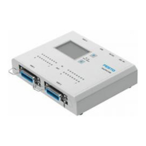
fitted Checkbox:
Tighten the union nuts of the plug connectors by hand.
Seal unused sockets with the protective caps supplied
4.1 Selection of the power supply unit
Warning
Electric shock
Injury to people, damage to the machine and system
Only use PELV circuits in accordance with IEC 60204-1 (protective extra-low
voltage, PELV) for the electrical power supply.
Observe the general requirements of IEC 60204-1 for PELV circuits.
Use only voltage sources that guarantee a reliable electric separation of oper
ating and load voltage in accordance with IEC 60204-1.
Make sure the power supply unit fulfils the requirements specified in the Check
box data sheet with regard to voltage, current and power.
Allow for a sufficient power reserve.
Observe the power consumption of connected consumers as well as system
expansions.
4.2 Connection of the operating voltage
Warning
Risk of fire
Protect the supply cable with a 4 A fast-acting fuse.
Use an operating voltage cable with a suitable cable cross section
Avoid long distances between the power supply unit and the Checkbox. Long
operating voltage cables reduce the voltage supplied by the power supply unit.
Connect the Checkbox to the operating voltage as follows:
Pin 24 V DC plug connection
1Do not connect
2+24 V DC, -15 % +20 %; protect with
4 A fast-acting fuse
3GND
4FE
4.3 Power supply for external components
When connecting the Checkbox to other devices (e.g. PLC, conveyor device) via the
connections PLC, ACTUATORS or BUFFER/FEEDER, do not connect the potential at
the “24 V DC” connection of the Checkbox with other plug connectors of the
Checkbox.
Consuming devices can also be supplied with voltage via the PLC plug.
Also observe the information in the èCHB-C-N description, chapter 3.6.
4.4 Actuators
Actuators connection socket
A/1 Actuator 3
1
43
2
5
A/2 Actuator 2
3GND
A/4 Actuator 1
5Do not connect
4.5 Buffer/Feeder
Buffer/Feeder connection socket
A/1 24 V DC / Box ready
– Reference voltage for sensors
(switched off in Stop status)
– Operating status
– Control for transporting device
(e.g. conveyor belt) 1
43
2
5
A/2 Feeder, control of the small parts con
veyor (e.g. upstream feeder bowl)
3GND, reference voltage for sensors
E/4 Buffer, buffer zone sensor 1
5Do not connect
4.6 Ethernet
Pin Signal M12 Ethernet connection socket1)
1 TD+ Transmitted data + 1
4
2
3
2 RD+ Received data +
3 TD- Transmitted data -
4 RD- Received data -
Metal covering Screening (shield)
1) d-coded
4.7 Encoder:
Encoder connection socket
Interface for rotary pulse generator as per RS 485
specification
1
2
3
45
67
8
1 A+
2 n.c.
3 B+
4 A-
5 B-
65 V supply 1)
7GND
8 n.c.
1) Maximum loading 180 mA
