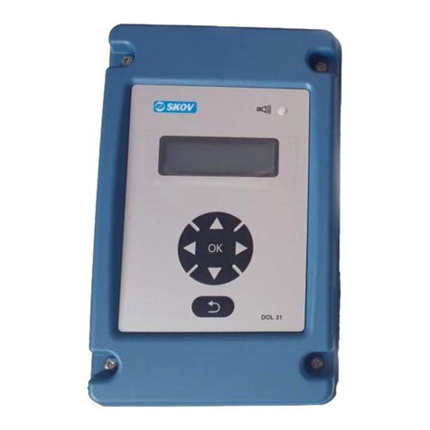
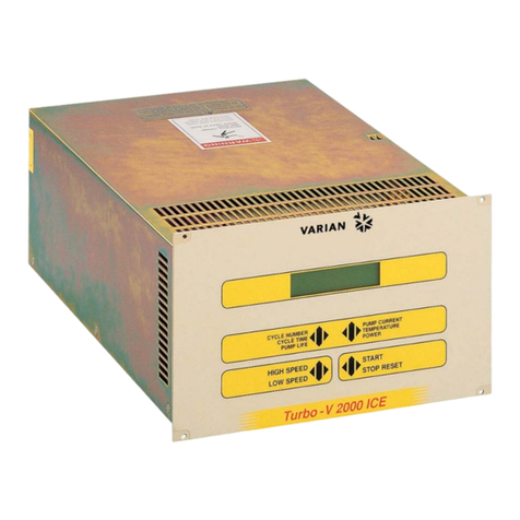
Himel ATSE2CM User manual

Internal
ATSECM Controller
Operation Manual

Internal
Table of Contents
1. Product Introduction .............................................................................................................. 4
2. Front panel touch button function .................................................................................... 5
3. Front panel LED......................................................................................................................... 6
4. Working mode .......................................................................................................................... 7
5. Main menu ................................................................................................................................. 7
6. Wiring diagram ....................................................................................................................... 15
7. Mechanical dimension and panel opening ................................................................... 18
8.Technical parameters ............................................................................................................. 18
Attention:
- The complete set must including 3 set of ACB,cable interlock ,220VAC
motor/shunt release /closing coil / ATS Controller
- Do not install key lock with ACB, it will damaged the ACB when automatic
transfer
- Do not install the under voltage release with ACB, It will impact ATS
automatic transfer
- Do not use ACB's MODBUS or remote signal to Switch ON/OFF breaker by
MX/XF, It will impact the ATS automatic transfer
- Please refer to HDW3 air circuit breaker’s user manual before installed
ACB
- Please refer to HDW3 cable mechanical interlock ‘s user manual before
assemble mechanical interlock with ACB

Internal
- Default with 3m controller cable

Internal
1.Product Introduction
ATSE2CM automatic transfer controller is an intelligent ATSE controller with programmable
functions, automatic measuring, LCD menu display, and digital communication. It can automatically realize
voltage, frequency, phase etc. electrical parameters measurement and automatic control according to
setting strategy which can reduce human operation error. It is an ideal product of ATSE.
ATSE2CM automatic transfer controller consists of microprocessor as core. It can precisely detect
two- source 3-phase voltage and make precise recognition about abnormal voltage (over-voltage, under-
voltage, missing phase, over-frequency, under-frequency) and output passive control digital. This device
can be widely applied to power plant, post and telecommunications, petroleum, coal, metallurgical, railway,
municipal, intelligent building etc.
Functional parameter
●Graphic LCD 800x480 pixel, 5 inch TFT;
●Two-source AC power input: 3-phase 4-wire;
●Measured values, settings, and message texts are supported in English and Chinese;
●12~30VDC power supply;
●Detection function for over-voltage, under-voltage, phase loss, reverse phase sequence, over-frequency,
under-frequency;
●8-channel programmable digital input (grounding effective);
●10-channel programmable digital output;
●Integrated RS-485 isolation interface, MODBUS protocol;
●Storage of last 200 events;
●Real time clock;
●All parameters are field programmable, use password access to avoid mis-operation by unprofessional
persons;
●The fixed washer is IP65 degree of protection;
●Module structure design, Retardant PC cover, pluggable terminal, embedded installation mode,
compact structure and easy installation;

Internal
2.Front panel touch button function
Icon Key name Function description
101 Key In Manual mode, press this button to transfer breakers S1-
TIE-S2 to ON-OFF-ON(101 )
110 Key In Manual mode, press this button to transfer breakers S1-
TIE-S2 to ON-ON-OFF (110 )
011 Key In Manual mode, press this button to transfer breakers S1-
TIE-S2 to OFF-ON-ON (011 )
100 Key In Manual mode, press this button to transfer breakers S1-
TIE-S2 to ON-OFF-OFF (100 )
001 Key In Manual mode, press this button to transfer breakers S1-
TIE-S2 to OFF-OFF-ON (001 )
000 Key In Manual mode, press this button to transfer breakers S1-
TIE-S2 to all OFF (000 )
Test mode Key Press this Key for 3 seconds to enter test function
Auto mode Key Press this Key for 3 seconds to set controller as Auto
mode.
Manual mode
Key
Press this Key for 3 seconds to set controller as manual
mode
Programming
mode Key
Press this Key for 3 seconds to set controller as
programming mode.
Increase/ up Key
In menu page, press this Key to scroll page.
In parameter setting page.
Press this key to up cursor or increase value.
Decrease / down
Key
In menu page, press this Key to scroll page.
In parameter setting page.
Press this key to down cursor or decrease value..
Enter Key Press this Key to enter sub-menu or confirm setting
information.
Return Key
Press this Key to return prior menu screen, press this button
for 3 seconds to lock/unlock the button. press it can clear
fault alarm when alarm occur.

Internal
3.Front panel LED
●Alarm LED (Red) –when fixed, indicates an alarm is active;
●S1 voltage status LED (Green) –S1 normal, fixed; S1 abnormal, blinking;
●S2 voltage status LED (Green) –S2 normal, fixed; S2 abnormal, blinking;
●Qs1 switch status LED (Green) –on, Qs1 close; off , Qs1 open;
●Qs2 switch status LED (Green) –on, Qs2 close; off, Qs2 open;
●Qtie switch status LED (Green) –on, Qtie close; off, Qtie open;

Internal
4.Working mode
● Programming mode: Parameter setting operation under this mode, long pressing “programming mode”
key for 3s to enter, set password before visiting programming menu.
● Manual mode: Can control switch manually, long pressing “manual mode” button for 3s to enter,
pressing 101 key、110 key、011 key、100 key、001 key、000 key switch the switch to the corresponding
state.
● Automatic mode: Long pressing “automatic mode” button for 3s to enter. Under automatic mode, device
automatically executes operation of open/close switch and start/stop generator. When the time of
exceeding limit of prior source is longer than the set delay time, the device will open the load of the main
source and connect to the emergency source.
5.Main menu
●Main menu consists of Public parameters, System parameters, Switch setting, Programmable Control,
communication parameters and Language Menu, Disconnect the alarm to make it convenient for user to
fast visit measuring value and revise parameters.
●Parameter setting: This operation is only valid under the programming mode. When there are changes
of parameter, it will show “save parameter?” before returning to main menu. Select ”YES” to save
parameters.

Internal
5.1、Public parameters
No Option Definition Default
值 Adjustment Range
1.1 SYSTEM TIME \ \ Real time
1.2 BACKLIGHT Min Active Active /1-30 Min
1.3 BRIGHTNESS
REGULATION Standby / work 15/30 0-100/10-100
1.4 PERMISSIONS
VALID TIME Min Active Active /1-30 Min
1.5 USER
PASSWORD \ 1000 0000-9999
5.2、System parameters
No Option Definition Default Adjustment Range
2.1 NETWORK Network Type 4NBL 4NBL
2.2 NOM.VOLT. P-P Voltage 400 50-690V
2.3 APP M-M:Mains to Mains Supply M-M M-M
2.4 RETURNS Inhibit the automatic
retransfer
Automatc
retransfer
to the
priority
source
Automatic retransfer
to the priority source /
Don’t automatic
retransfer to the
priority source
2.5 NOM.FREQ. Nominal network frequency 50 Hz 50/60Hz
2.6 POT PH. Select and verify Phase
Sequence OFF L1L2L3/ L3L2L1/ OFF
2.7 1RT Source I Return Timer 3S 0-99S
2.8 1FT Source I Failure Timer 3S 0-99S
2.9 2RT Source II Return Timer 3S 0-99S
2.10 2FT Source II Failure Timer 3S 0-99S
2.11 UND.U Under-voltage threshold 85% 70-95%
2.12 UND.U.HYS Under-voltage hysteresis 95% 75-100%
2.13 OV.U Over-voltage threshold 115% 105-130%
2.14 OV.U.HYS Over-voltage hysteresis 110% 100-125%
2.15 UND.F Under- Frequency threshold 95% 80-99%
2.16 UND.F.HYS Under- Frequency hysteresis 97% 88-100%
2.17 OV.F Over- Frequency threshold 105% 101-120%
2.18 OV.F.HYS Over- Frequency hysteresis 103% 100-119%

Internal
5.3、Switch setting:
No Option Definition Default Adjustment Range
3.1 Signal hold time Pulse time of the opening and
closing relay output 0.5S 0.1-20.0S
3.2 Action timeout time
When the output pulse is timed,
If DI is not detected within the
set time, the alarm is given
0.5S 0.1-90.0S
3.3 Interlock time
The waiting time of the interlock
that before or after the closing of
the TIE Breaker
0.5 0-2.0S
5.4、Programmable Control:
Input function
No Option Default Adjustment Range
4.1 Digital Input 1-2
4.1.x.1 Input function
4.1.x.2 Contact Type NO NO/NC
4.1.x.3 Input delay 0.05S 0.01-600.00S
4.2 Digital Output 0
4.2.x.1 Output function
4.2.x.2 Contact Type NO NO/NC
Input Menu Input code definition
Inhibit Inhibit input function
Forced to pos.
0
The transfer switch is immediately driven to 0 position,and the controller in manu mode,
meantime,when the input signal disappear,the controller feedback to auto mode
Priority Priority network select; change S1 or S2 priority state when input is activated, return to
current priority state when input is not activated
Remote
control Remote control is enable when input is activated
Remote
position I Switch transfer to position I when input is activated
Remote
position II Switch transfer to position II when input is activated
Remote
position 0 Switch transfer to position 0 when input is activated
Test off load Activates on an off load test,this will start/stop the generator without transferring the load
to S2
Test on load Activates on an on load test,this will start/stop the generator with transferring the load to
S2
LS Verify the generator don’t overload before transfer to S2

Internal
notes:INPUT1, INPUT2 and INPUT3 solidify for detecting Qs1, Qs2 and Qtie open or close state;INPUT4,
INPUT5 and INPU6 solidify for detecting the fault state of Qs1, Qs2 and Qtie.
Output function
Output Menu Output code definition
Inhibit Inhibit output function
ATS ready The output signal is activated when switch and controller are OK
SI available The output signal is activated when SI available
SII available The output signal is activated when SII available
Alarm The output signal is activated when controller failure
Manu mode The output signal is activated when controller in manu mode
Auto mode The output signal is activated when controller in auto mode
Test mode The output signal is activated when controller in auto mode
Position I The output signal is activated when ATS in position I
Position II The output signal is activated when ATS in position II
Position 0 The output signal is activated when ATS in position 0
Forced to pos. 0 The output signal is activated when ATS forced to 0 position
LS Verify the generator don’t overload before transfer to S2
ATS Source N Auxiliary Source N
ATS Source A Auxiliary Source A
ATS Source B Auxiliary Source B
ATS Source C Auxiliary Source C
Start generator When APP is M-G/G-M, the mains source failure,the output signal is activated
Universal The Communication control
5.5、Communication parameters
No Option Default Adjustment Range
6.1 Serial node address 3 001-254
6.2 Serial Baud rate 19200 2400/4800/9600/
19200/38400
6.3 Data format 8N 8N/8O/8E/7O/7E
6.4 Stop bit 1 1/2
5.6、Language :
No Option Definition Default
6.1 Language setting \ Chinese Chinese/English

Internal
●Power supply status icon, refer to pic1
page example Note
Pic.1
Power supply
status
●Data display icon, refer to pic2-pic8
page example Note
Pic2 .
Data display
Phase voltage(220V)
Pic3.
Data display
Line voltage(380V)

Internal
Pic4.
Data display
Data display of the
required conditions for
synchronous transfer
Pic5.
Data display
Programmable input, if
there is signal detected in
01 input port, then the 01
will be selected.
Pic6.
Data display
Programmable output, if
there is output action in 01
output port, the 01 will be
selected.
Pic7.
Data display
Statistic data

Internal
Pic8.
Data display
Real time clock
●Alarm status icon, refer to pic9
page example Note
Pic9.
Alarm status
Alarm status, If there is
A01 alarm, A01 in the pic
will be selected
●Commissioning icon, refer to pic9
page example Note
Pic10.
Commissioning
menu
Simulation test
●Event record Icon, refer to pic11
page example Note

Internal
Pic11
Event record
Device Event record

Internal
6. Wiring diagram
6.1 Terminal definition and description:
Terminal
No. Item Function description Note
1 L1
S1 AC 3-phase 4-wire voltage input L1,N are AC power supply
terminal.
2 L2
3 L3
4 N
5 L1
S2 AC 3-phase 4-wire voltage input L1,N are AC power supply
terminal.
6 L2
7 L3
8 N
17 COM Module grounding Module ground terminal
18 INPUT1 Break1 closure detection
Grounding effective
19 INPUT2 Break2 closure detection
20 INPUT3 Break-TIE closure detection
21 INPUT4 Break1 fault detection
22 INPUT5 Break2 fault detection

Internal
23 INPUT6 Break-TIE fault detection
24 INPUT7 input port function defined by user
25 INPUT8
26 A RS485 communication interface RS485A
27 B RS485B
28 SG RS485 grounding
29 BATTERY+ Positive electrode of DC power supply
30 BATTERY- Negative electrode of DC power supply
31 OUT10 Relay COM auxiliary power output port
10A
32 Relay NO
33 Relay NC
34 OUT9 Relay COM auxiliary power output port
10A
35 Relay NO
36 Relay NC
37 OUT8 Relay COM Genset start output port
10A
38 Relay NO
39 Relay NC
40 OUT7 Relay COM Programmable output port
10A
41 Relay NO
42 Relay NC
43 OUT6 Break-TIE OPEN Programmable output port
10A
44 COM 43 and 45 Common
45 OUT5 Break-TIE CLOSE Programmable output port
10A
46 OUT4 Break2 OPEN Programmable output port
10A
47 COM 46 and 48 Common
48 OUT3 Break2 CLOSE Programmable output port
10A
49 OUT2 Break1 OPEN Programmable output port
10A
50 COM 49 and 51 Common
51 OUT1 Break1 OPEN Programmable output port
10A

Internal
6.2.Terminal diagram (ATSECM controller with air circuit breaker)

Internal
7. Mechanical dimension and panel opening
8.Technical parameters
1.AC supply: terminal 3,4 and 7,8
Rated voltage 400VAC(LL)
Operating limit value 90-415VAC(LN)
Frequency 45-65Hz
Power consumption 10W
2.DC supply:terminal 29,30
Rated battery voltage 24VDC
Operating limit value 10-30VDC
Max power consumption 10W
3.Digital input:terminal 17—25
Input type negative
Input current ≤8mA
Low input signal ≤1.0V
High input signal ≥3.0V

Internal
4.RS485 serial interface:terminal 26,27,28
Interface Type isolation
Baud rate 2400-38400bps
5、Output 31-33(OUT10)、34-36(OUT9)、37-39(OUT8)、40-42(OUT7)
Contact Type single-pole double throw
Rated value DC:10A、30V,AC:10A、250V
6、Output 43(OUT6)、45(OUT5)、46(OUT4)、48(OUT3)、49(OUT2)、51(OUT1)
Contact Type single-pole single throw
Rated value DC:10A、30V,AC:10A、250V
7.Working environment condition
Working temperature -25℃-70℃
Storage temperature -30℃-80℃
Relative humidity 20%-93%
Max environmental pollution Level 3
Table of contents
