manuals.online logo
Brands
  1. Home
  2. •
  3. Brands
  4. •
  5. Vortice
  6. •
  7. Controllers
  8. •
  9. Vortice IREM 5 User manual

Vortice IREM 5 User manual

Libretto d’istruzioni
Instruction booklet
Notice de pose et d’entretien
Betriebsanleitung
Folleto de instrucciones
Gebruiksaanwijzing
Instruktionshäfte
IREM 3 - 5 - 9
MADE IN ITALY COD. 2/0/00
IP54
VORTICE LIMITED
Milley Lane - Hare Hatch
Reading - Berkshire - RG10 9TH
Tel. (+44) 118-94.04.211
Fax (+44) 118-94.03.787
UNITED KINGDOM
VORTICE ELETTROSOCIALI S.p.A.
Strada Cerca, 2 - frazione di Zoate
20067 TRIBIANO (MI)
Tel. (+39) 02-90.69.91
Fax (+39) 02-90.64.625
ITALIA
VORTICE FRANCE
72 Rue Baratte-Cholet
94106 Saint Maur Cedex
Tel. (+33) 1-55.12.50.00
Fax (+33) 1-55.12.50.01
FRANCE
4
DESCRIZIONE E IMPIEGO
I dispositivi denominati IREM 3, IREM 5 ed IREM 9
sono apparecchi ad alta tecnologia e costruiti a regola
d’arte, destinati alla regolazione manuale di uno o più
motori, monofase o comunque contraddistinti da
carico ohmico-induttivo, caratterizzati da intensità
massima complessiva di corrente non superiore
rispettivamente a 3, 5 e 9 A. La tabella a pag. 6 indica
gli accoppiamenti regolatore-singolo prodotto
(industriale). Si noti che il modello IREM 9 è
specificamente destinato alla regolazione simultanea
di piùapparecchi.
I dispositivi IREM non sono adatti alla regolazione di
carichi di tipo capacitativo.
Una spia luminosa, conglobata nell’interruttore
bipolare, segnala la presenza di tensione sul carico.
I regolatori sono altresìdotati di potenziometro per la
regolazione della tensione sino ad un valore minimo,
preimpostabile mediante apposito trimmer.
Il modello IREM 9 èinoltre provvisto di dissipatore
alettato destinato a migliorare lo smaltimento termico.
Description and use
The IREM 3, IREM 5 AND IREM 9 are high-tech,
state-of-the-art manual regulators for operation with
one or more single-phase ohmic-inductive load
electric motors with maximum overall current ratings
of 3, 5 and 9 amperes respectively. The table on
page 6 shows the couplings between the regulators
and the individual industrial products. As can be seen,
the IREM 9 is specifically designed for regulating
several motors simultaneously.
These IREM regulators are not designed for
regulating capacitance type loads.
The two-pole switch incorporates an indicator light
that turns on when the load is under voltage.
Each regulator also has a potentiometer for adjusting
voltage down to a minimum value, depending on the
trimmer setting.
The IREM 9 regulator is also provided with a fin-type
dissipater for improving heat dissipation.
Description et mode d’emploi
Les dispositifs appelés IREM 3, IREM 5 et IREM 9
sont des appareils àhaute technologie, construits
dans les règles de l’art, destinés au réglage manuel
d’un ou plusieurs moteurs, monophasés, ou de toute
façon qui se distinguent par une charge ohmique-
inductive et se caractérisent par une intensité
maximum totale de courant non supérieure à3, 5 et 9
A respectivement.La table reportée àla page 5 indique
les couplages régulateur-produit individuel (industriel).
Note: le modèle IREM 9 est spécifiquement destiné
au réglage simultanéde plusieurs appareils.
Les dispositifs IREM ne sont pas adaptés au réglage
de charges de type capacitatif.
Un voyant lumineux englobédans l’interrupteur
bipolaire signale la présence de tension sur la charge.
Les régulateurs sont eux aussi munis d’un
potentiomètre pour le réglage de la tension jusqu’à
une valeur minimum àfixer préalablement au moyen
d’un trimmer prévu àcet effet.
Le modèle IREM 9 est aussi muni d’un dissipateur à
ailettes destinéàen améliorer le refroidissement.
Beschreibung und Einsatz
Die benannten Vorrichtungen IREM 3, IREM 5 und
IREM 9 sind Hochtechnologieapparate, die nach allen
Regeln der Kunst konstruiert werden. Sie sind zur
manuellen Regulierung eines oder mehrerer Motoren
bestimmt, welche einphasig sind oder durch ohmisch-
induktive Last und durch eine
Gesamthöchststromstärke von 3, 5 und 9 A
gekennzeichnet sind. Die Tabelle auf Seite 6 zeigt die
Verbindung Regulator –Einzelprodukt (industriell) an.
Das Modell IREM 9 ist eigens dafür geschaffen, die
simultane Regulierung mehrerer Apparate zu
übernehmen.
Die Vorrichtungen IREM sind nicht für eine kapazitive
Regulierung geeignet.
Eine im zweipoligen Schalter integrierte
Anzeigelampe deutet das Vorhandensein von
Lastspannung an.
Die Regler sind außerdem mit Potentiometern zur
Spannungsregulierung bis auf einen Minimalwert, der
mittels entsprechenden Trimmern eingestellt wird,
ausgerüstet.
Das Modell IREM 9 ist darüber hinaus mit einem
Kühlkörper versehen, der die thermische
Wärmeableitung verbessert.
Descripción y empleo
Los dispositivos denominados IREM 3, IREM 5 e
IREM 9 son aparatos de alta tecnología construidos a
regla de arte, destinados a la regulación manual de
uno o varios motores, monofásicos o caracterizados
por carga ohmica-inductiva, con una intensidad
máxima total de corriente no superior a 3, 5 y 9 A
respectivamente. La tabla de la pág. 6 indica los
acoplamientos regulador-producto (industrial). Se hace
notar que el modelo IREM 9 estáespecíficamente
destinado a la regulación simultánea de varios
aparatos.
Los dispositivos IREM no son aptos para la
regulación de cargas de tipo capacitativo.
Un indicador luminoso, incorporado en el interruptor
bipolar, señala la presencia de tensión sobre la carga.
Los reguladores están además dotados de
potenciómetro para la regulación de la tensión hasta
un valor mínimo programable mediante trimmer.
El modelo IREM 9 estáademás provisto de disipador
con aletas destinado a mejorar la eliminación térmica.
Beschrijving en gebruik
De inrichtingen genoemd IREM 3, IREM 5 e IREM 9
zijn technologisch hoogwaardige, met grote vakkennis
vervaardigde apparaten die dienen voor het
handmatig regelen van een of meer motoren,
eenfasige of hoe dan ook gekenmerkt door
inductieve ohmse belasting, waarvan de totale
maximale stroomsterkte resp. de 3, 5 en 8 A niet
overschrijdt. De tabel op pag. 6 geeft de betreffende
gegevens ter regeling van het afzonderlijke
(industriële) product aan. Let erop dat model IREM 9
speciaal is bestemd voor de gelijktijdige regeling van
meerdere apparaten.
De IREM-inrichtingen zijn niet geschikt voor het
regelen van belastingen van het capacitieve soort.
Een rood LED dat zich in de tweepolige schakelaar
8
ENGLISH
•Do not use this product for any purpose other than
for one indicated in this booklet.
•After removing the product from its packing,
check it to see that it has not been damaged in
any way. When in doubt, contact your Vortice
Assistance Center. Do not leave loose packing
materials within reach of children or inexperienced
persons.
•The use or handling of any electrical appliance or
unit requires taking certain precautions:
- Never touch the equipment when your hands are
wet or humid.
- Never touch the equipment if you are barefoot.
- Do not let the equipment be used by children or
inexperienced persons.
•Do not operate the equipment in the presence of
inflammable materials such as alcohol, insecticide,
gasoline (petrol), etc.
•Before performing any cleaning or maintenance
operations on the equipment, disconnect it from the
power source.
•When the equipment is to be permanently removed,
first turn off the main switch and then disconnect it
from the power source. Store the equipment in a
place which is well out of reach of children and
inexperienced persons.
Caution:this symbol indicates that care must be taken to avoid injury
!
Precaution:
this symbol indicates that care must be taken to avoid damaging your product
!
•Do not make any modifications of any kind on the
product.
•The table on page 6 lists all the possible
applications of the unit. Some of the products
mentioned are not sold in all countries.
•Do not allow the unit to be exposed to the sun or
weather (rain, etc.).
•Do not rest any objects on the unit.
•Perform periodic visual inspection to check for
defects. If any are found, do not operate the unit and
immediately contact your Vortice Assistance Center.
•The power mains to which the unit is connected
must conform to the existing norms.
•Installation of the unit must only be done by a
qualified technician.
•The unit must be correctly connected to an efficient
grounding system, as prescribed by the existing
safety norms. When in doubt, have the system
carefully inspected by a qualified technician.
•Before connecting the unit to a power source, check
to make sure the power source meets the maximum
power requirements of the unit.If it does not,
immediately contact a qualified technician.
•When installing the unit, an omnipole, magneto-
thermal switch must also be installed. The switch
contact gaps must measure at least 3 mm.
•If the unit is dropped or receives a hard blow, have
the unit immediately checked at an authorized
Technical Assistance Center.
•If the unit develops a malfunction or operates
improperly, turn it off and immediately contact an
authorized Technical Assistance Center. If any parts
need replacing, be sure to request the use of
original Vortice spare parts.
•When the unit is not being operated, turn off its
main switch.
Trimmer Adjustment
Turn on the unit. Turn the potentiometer in the “–“
direction until it stops turning. Now rotate it in the “+”
direction until the desired minimum speed-regulation
interval is obtained.
ATTENTION:
•IP54 protection for the unit can be guaranteed only if
all the installation instructions given in this booklet
are carefully followed.
•Using a different type of regulator is not advised
because the controlled unit may function improperly
or be improperly regulated, and it may also operate
very noisily.
•The regulating unit on the TRM 10 and TRM15
turrets must be connect to the turret in the maximum
speed configuration.
The power-source data must be consistent with
the electrical data shown on the name plate A.
TECHNICAL CARACTERISTICS
IREM 3 IREM 5 IREM 9
Voltage (V) 220-240 220-240 220-240
Frequency (Hz) 50 50 50
Max Current (A) 3 5 9
Operating
temp. range (°C) -10÷+40 -10÷+40 -10÷+40
12
3
15
INSTALLATION -TRIMMER REGULATOR
INSTALLATION - REGLAGETRIMMER
INSTALLATION - EINSTELLUNGTRIMMER
INSTALACION - REGULACIONTRIMMER
INSTALLATIE - REGELING AVTRIMMER
INSTALLATION - REGLERING AVTRIMMER
INSTALLAZIONE - REGOLAZIONE TRIMMER
-
5
4
6
9MONOFASE 220-240 V
SINGLE-PHASE
MONOPHASÉ
EINPHASIG
MONOFÁSICO
ENFAS
EENFAZIG
16
7
8A
17
1110
1312
14

This manual suits for next models

2

Other Vortice Controllers manuals

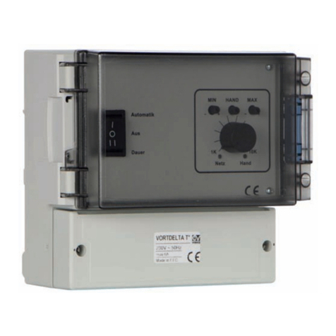
Vortice VORT DELTA T User manual

Vortice

Vortice VORT DELTA T User manual

Vortice CHANGEOVER TF User manual

Vortice

Vortice CHANGEOVER TF User manual

Vortice SCRR/M User manual

Vortice

Vortice SCRR/M User manual

Vortice C 1.5 User manual

Vortice

Vortice C 1.5 User manual

Vortice SCRR5 User manual

Vortice

Vortice SCRR5 User manual

Vortice SCB5 User manual

Vortice

Vortice SCB5 User manual

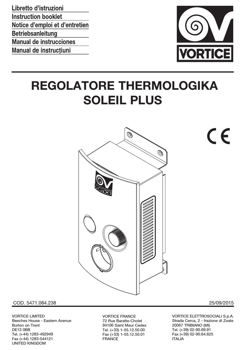
Vortice REGOLATORE THERMOLOGIKA SOLEIL PLUS User manual

Vortice

Vortice REGOLATORE THERMOLOGIKA SOLEIL PLUS User manual

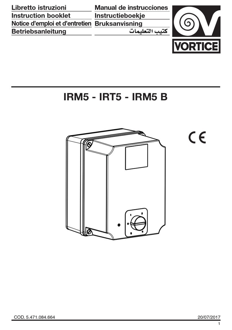
Vortice IRM5 Series User manual

Vortice

Vortice IRM5 Series User manual

Vortice C 1.5 User manual

Vortice

Vortice C 1.5 User manual

Vortice IRET 6 User manual

Vortice

Vortice IRET 6 User manual

Vortice C 2.5 User manual

Vortice

Vortice C 2.5 User manual

Vortice Vort Delta T WIFI User manual

Vortice

Vortice Vort Delta T WIFI User manual

Vortice CNU User manual

Vortice

Vortice CNU User manual

Vortice SCRR5 User manual

Vortice

Vortice SCRR5 User manual

Vortice IREM 3 User manual

Vortice

Vortice IREM 3 User manual

Popular Controllers manuals by other brands

Kromschroeder TC technical information

Kromschroeder

Kromschroeder TC technical information

red lion PXU100B0 instructions

red lion

red lion PXU100B0 instructions

Hobby-Wing EZRUN MAX10 G2-140A user manual

Hobby-Wing

Hobby-Wing EZRUN MAX10 G2-140A user manual

AL Tech ALTHC023 Installer Manual and Quick Guide

AL Tech

AL Tech ALTHC023 Installer Manual and Quick Guide

i-MO i3N Series user manual

i-MO

i-MO i3N Series user manual

flakt woods EMPA Installation and adjustment

flakt woods

flakt woods EMPA Installation and adjustment

Redline Connect Series Installation guidelines

Redline

Redline Connect Series Installation guidelines

KEBCO COMBIVERT F6 Instructions for use

KEBCO

KEBCO COMBIVERT F6 Instructions for use

Aqua Medic Ocean Light LED Operation manual

Aqua Medic

Aqua Medic Ocean Light LED Operation manual

Delta DVP14ES00R2 instruction sheet

Delta

Delta DVP14ES00R2 instruction sheet

HIK VISION DS-k2210 quick start guide

HIK VISION

HIK VISION DS-k2210 quick start guide

UltraLift Prolift Advanced Programming guide

UltraLift

UltraLift Prolift Advanced Programming guide

Samwontech Nova Series instruction manual

Samwontech

Samwontech Nova Series instruction manual

Timeguard MTLW3000 Installation & operating instructions

Timeguard

Timeguard MTLW3000 Installation & operating instructions

Jetline 9600 Series Operation manual

Jetline

Jetline 9600 Series Operation manual

GOAL ZERO EXTERNAL MPPT Install instructions

GOAL ZERO

GOAL ZERO EXTERNAL MPPT Install instructions

AutomationDirect DL205 user manual

AutomationDirect

AutomationDirect DL205 user manual

MaxPower CT25 Installation operation & maintenance

MaxPower

MaxPower CT25 Installation operation & maintenance

manuals.online logo
manuals.online logoBrands
  • About & Mission
  • Contact us
  • Privacy Policy
  • Terms and Conditions

Copyright 2025 Manuals.Online. All Rights Reserved.