Dynalite DUS804C-DALI User manual

DUS804C-DALI
Ceiling Mount Universal Sensor Installation Manual
The DUS804C-DALI is a low profile recessed flush mount 360º ceiling mount sensors that combines
motion detection (PIR) and ambient light level detection (PE) in one device. The sensor is powered directly
by the DALI network that is running between the DALI fittings, eliminating the need for additional network
field wiring or network power cables. The sensor can only be used when connected to the DALI port of the
DDBC120-DALI unit.
In applications such as office buildings, lecture theatres, and homes, the DUS804C-DALI multi function
sensor can be utilised to detect different levels of motion and switch on the lights. The sensor can detect
movements over a 7.42m x 5.66m area with a mounting height of 2.4m. When an area is unoccupied the
sensor can detect this and the lights can be automatically dimmed or switched off to provide energy
savings. The unit also incorporates a segmented click-up bezel surrounding the motion sensor element.
This enables a portion of the sensing field to be readily masked to prevent nuisance detection from
adjacent doorways or corridors. In situations where it is critical to maintain precise lighting control for
individual workspaces, such as an office workstation or even air traffic control centers, the DUS804C-DALI
facilitates light compensation. The DUS804C-DALI can also be placed in an automatic “Daylight
Regulation” mode for additional energy savings.

instructions
2DUS804C-DALI Installation Manual Rev B.docx
This unit is for indoor use only. This unit is designed for installation in a 64mm diameter hole where the
ceiling void is at least 40mm deep. Select an appropriate indoor mounting location, as detailed in the location
guidelines on the following pages. Note that the product has two functions, and the optimum mounting
location for each individual function may conflict with each other, and may require use of multiple sensors.
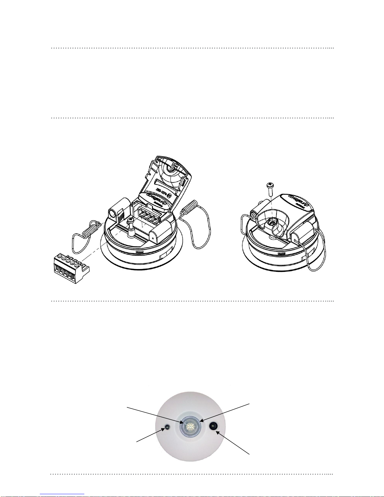
DUS804C-DALI network connections
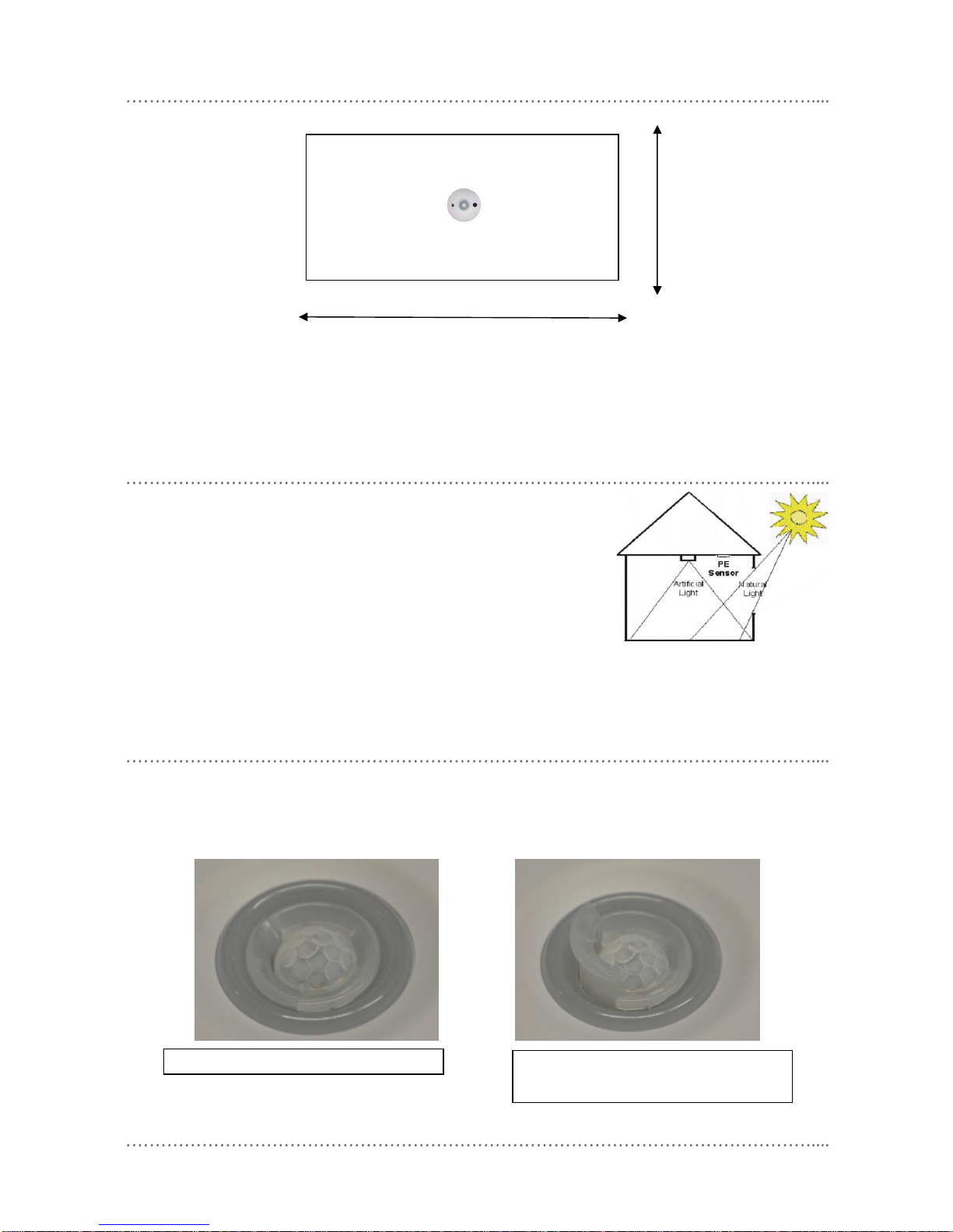
Motion detection mounting location
•Power down & isolate DALI bus prior to wiring the device
•Fix the sensor to a firm section of ceiling
•Position the sensor so it is between 2.1 and 4.0m from the floor. Optimum height is 2.4m
•Position the sensor so it is at least 1m away from electrical lighting such as neon and fluorescent lights
•Position the sensor as to avoid exposing it to direct sunlight, glare and heating/cooling sources
•Position the sensor where pedestrian traffic is likely to walk across the detection zones (see motion
detection coverage diagram)
•Note that for the DUS804C-DALI coverage area is rectangular (see Motion Detector coverage diagram)
•For programming instructions refer to Dynalite Tech Note - Setting up Motion Detector function
DALI cable connected to sensor.
The sensor has been designed for the DALI network to loop through and then loop out to the next device.
The different DALI network devices can be connected in any order along the network. The sensor does not
need to be directly connected to the lighting groups that is to be controlled.
PIR sensor
DALI network
sign on button
Light level sensor
Click-up bezel for
motion shield

motion detector coverage at 2.4m mounting height
DUS804C-DALI Installation Manual Rev B.docx 3
photo electric cell mounting location
Position the sensor so it “sees” a combination of artificial light and
natural light indirectly.
Position the sensor so it is not directly exposed to artificial light or
sunlight and glare.
Ensure that the sensor is directed onto working surfaces were
correct light level is required.
For programming instructions refer to Dynalite Tech Note - Setting up PE
functions
masking regions from motion detection
The DUS804C-DALI has a built in pull up mask that can be rotated to remove 120oscanning range from the sensor. This feature can be
used in situation when a section of the motion detection zone needs to be blocked out. When mounting the sensors in a single office the
mask can be used to block out motion that would be detected in the corridor causing false triggering of the sensor and then turning on
the lighting unnecessary. This feature does not affect the light level detection functionality of the sensor.
5.66m
7.42m
Lens mask down. Full 360o of scanning available.
Lens mask up removing 120o scanning range
from the PIR, leaving only 240o. The mask can be
rotated to adjust the area being blocked out.

specifications
4DUS804C-DALI Installation Manual Rev B.docx
DUS804C-DALI Installation Manual Rev A.doc. Specifications and design subject to change without notice. Philips Dynalite manufactured by WMGD Pty Ltd (ABN 33 097 246 921). All rights reserved. Dynalite,
Dimtek, DyNet and DLight and associated logos are the registered trademarks of Dynalite Intelligent Light Pty Ltd. Not to be reproduced without permission.
Email dynalite.info@philips.com Web: philips.com/dynalite
DUS804C-DALI:
Standard Sensitivity
Maximum detection range: 5.0m
Detection Area: up to 7.4m x 5.6m rectangular
(at a height of 2.4m)
Detection speed: 1.0m/s
Detection object: 700mm x 250mm
Detection zones: 64
LED activation indicator
Sensor: Quad element pyro-electric
PE Cell
Range <5 lux to >5000 lux (reflected)
Automatic “Daylight Harvesting” mode
Controls
Walk test/ LED indicator
Service switch
DALI power Consumption
9mA Max @ (Total of 10 user interfaces on one DALI
universe)
Control Bus
DALI bus for use with Philips Dynalite multi master
controller only
Terminals
5 way removable terminal strip, 1 x 1.5mm2max
individual conductor size
Operating Environment
0oC to 40oC ambient temperature
0% to 90% RH non condensing
Dimensions
72mm diameter x D 37mm
Weight
Packed weight 0.116kg
DALI power consumption
9mA (Total of 10 user interface on one DALI
universe)
WARNING: Do not connect any DALI terminals or
wires to mains power. DALI wires are NOT SELV and
should never be considered touch safe. Basic
insulation or higher is required between DALI wires
and mains cabling.
All dimensions shown in mm.
Table of contents