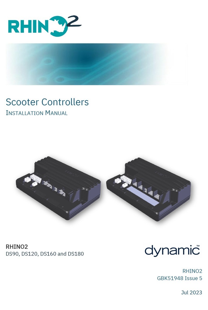
Dynamic DX Series User manual

DX-GB
Gearless Brushless
Installation Manual
MT
GBK64947 Issue 1,June 2007

About this Manual
This manual has been designed to help you install and configure a Dynamic DX-GB
powerchair control unit for a ‘generic’ brand powerchair. For this reason there are no
guidelines for specific applications.
This manual must be read in conjunction with all other relevant DX-System manuals.
If there is a specific requirement for your application, please contact Dynamic Controls
or one of the sales and service agents, to assist you.
Throughout this manual there are a few symbols that will help you quickly identify the
purpose of the paragraph that follows:
Notes & Precautions:
Notes provide supporting information for the previous paragraph or
section that should be followed in order to install, configure, and use
the product safely and efficiently.
Warnings:
Warnings provide important information for the previous paragraph or
section that must be followed in order to install, configure, and use the
product safely and efficiently.
Programming notes:
This icon denotes that the paragraph refers to the programming.
The term ‘programming’ used throughout this manual refers to adjusting parameters and
configuring options to suit an application. ‘Programming’ does not change or alter any
software within the controller and is performed using a controlled programming tool
available only to authorised personnel.
The term ‘accessory’ used throughout this manual refers to equipment that is ancillary to
the main functioning of the control system. It does not refer to an accessory of the
wheelchair. The control system is a component of the wheelchair.
DX is not user serviceable. Specialized tools are necessary for the repair of any
component.
Do not install, maintain or operate this equipment without reading, understanding and
following this manual – including the Safety and Misuse Warnings – otherwise injury or
damage may result.
Due to continuous product improvement Dynamic reserves the right to update this
manual. This manual supersedes all previous issues, which must no longer be used.
Dynamic reserves the right to change the product without notification.
Any attempt to gain access to or in any way abuse the electronic components and
associated assemblies that make up the powerchair system renders the
manufacturer’s warranty void and the manufacturer free from liability.
Dynamic and the Dynamic logo are trademarks of Dynamic Controls.
GBK64048: Issue 1 – June 2007
2

MT
All other brand and product names, fonts, and company names and logos are
trademarks or registered trademarks of their respective companies.
Dynamic owns and will retain all trademark rights and Dynamic or its licensors own
and will retain all copyright, trade secret and other proprietary rights, in and to the
documentation.
All materials contained within this manual, in hard copy or electronic format, are
protected by copyright laws and other intellectual property laws.
© Copyright 2006 Dynamic Controls. All rights reserved
3

Contents
1Introduction.............................................................7
1.1 The DX system........................................................................................ 7
1.2 The DX-GB Gearless Brushless controller ........................................... 8
2Installation and Testing ........................................10
2.1 DX-GB Mounting .................................................................................10
2.2 Connections and Wiring....................................................................11
2.2.1 Cable and Connector Pin-outs............................................12
2.2.2 Battery Connections..............................................................12
2.2.3 Motor and Park Brake Connections.................................... 14
2.2.4 DX BUS Connections .............................................................. 14
2.3 Drive Control Input (DCI) and OBC Connections.........................15
2.3.1 DCI – Analog Mode...............................................................16
2.3.2 DCI – Digital Mode.................................................................16
2.3.3 DCI Examples .......................................................................... 16
2.4 Motor Calibration................................................................................18
2.5 Testing the Installation........................................................................18
3Programming ........................................................20
3.1 Introduction .........................................................................................20
3.2 Description of Parameters.................................................................21
3.2.1 Modified System Drive Parameters......................................22
3.2.2 DX-GB Specific Parameters..................................................24
3.3 DX-GB parameter access list............................................................ 27
3.3.1 Hand Held Programmer (HHP) parameter list ................... 27
3.3.2 Wizard parameter access list...............................................27
4Diagnostics............................................................33
4.1 Introduction .........................................................................................33
4.2 Diagnostics Tools.................................................................................33
4.3 Flash Codes..........................................................................................34
4.4 User Advice and Error Codes............................................................35
4.4.1 User Advice List .......................................................................36
4.4.2 Error Codes ..............................................................................36
5Specifications........................................................38
5.1 Specifications of the DX-GB controller............................................ 38
5.1.1 Electrical specifications.........................................................38
5.1.2 Physical Specifications...........................................................39
5.2 Specifications of the Euro GB Motor ...............................................40
5.2.1 Electrical and mechanical specifications .........................40
5.2.2 Performance charts...............................................................41
5.2.3 Physical specifications...........................................................42
GBK64048: Issue 1 – June 2007
4

MT
6Appendices ..........................................................43
6.1 Programming Accessories.................................................................43
6.2 Intended Use and Regulatory Statement......................................44
6.3 Maintenance....................................................................................... 45
6.4 Warranty...............................................................................................46
6.5 Safety and Misuse Warnings.............................................................47
6.6 Electromagnetic Compatibility (EMC)............................................49
6.7 Environmental Statement..................................................................50
5

GBK64048: Issue 1 – June 2007
6

MT
1Introduction
1.1 The DX system
DX is a modular, expandable power wheelchair control system. This modularity allows
the system to be expanded and customized to particular end-user needs and
handles the requirements from basic driving to full environmental control. A power
module and a master remote are required along with a DX BUS cable to form the
base of any DX system. A variety of modules are available to access additional
functions and features.
An example DX system:
DX Power
Module
24V
Powerchair
Battery
DX-ECU
To HHP or Wizard
To Battery
Charger
DX Master Remote
Example DX Module
Actuator
Optional DX BUS
DX-CLAMB
DX BUS
Example
DX Module
Optional DX BUS
7

1.2 The DX-GB Gearless Brushless controller
The Dynamic DX Gearless Brushless Power Module (DX-GB) is a DX BUS compatible
module that converts signals generated by a DX Remote into high current outputs.
These outputs drive the motors that control the powerchair speed and direction. The
combination of a DX-GB and DX Master Remote give an exceptionally smooth,
powerful, and safe drive system.
The DX-GB has been designed specifically for use with Gearless Brushless motors, an
alternative to conventional brushed motors commonly in use today. Supplying up to
100-Amps per phase, the DX-GB is perfect for the control of a wide range of
powerchair configurations, including front, mid, and rear wheel drive.
Warning:
DX-GB is ONLY compatible with DX Systems containing recent Master
Remotes like the DX-REMG90(x,) the DX-REMG91 or later. Contact
Dynamic to check compatibility with other variants or custom
remotes.
The DX-GB is fully programmable to cater for the wide range of powerchair types and
user needs. Correct installation and programming are essential to ensure optimum
performance and safety.
A DX wheelchair control system comprises of two or more compatible
modules. Each module has its own installation manual.
This manual describes the DX-GB only and therefore must be read in
conjunction with the other DX Modules to be used in your application.
GBK64048: Issue 1 – June 2007
8

MT
DX-GB Power Module
Other DX
module
OBC
DCI
Alternative On-board
Battery Charger
Drive Control Input
Moto
r
Motor
G90 or G91
Charger
Programmer
(HHP or PC)
Other DX
module
24V Battery
9

2Installation and Testing
2.1 DX-GB Mounting
74 mm
2.91"
115 mm
4.53"
M5 x 10mm or #10/32 x 0.39" (max)
TYP x 3
The DX-GB must be mounted with the lid-down and at a minimum incline of
5° from horizontal.
GBK64048: Issue 1 – June 2007
10
5° min, 90° max
The position and orientation must give maximum mechanical protection to
the DX-GB.
Mount the DX-GB out of the path of water splashes from the wheels or the
motor housing. Make sure the DX GB will never be immersed in water.
Protect the front (connector panel) of the DX-GB from direct splashing.
Failure to adhere to the mounting orientations specified might lead to
water ingress, which can result in system malfunction and long-term
damage to the unit.

MT
For peak performance, locate the DX-GB so that air can flow over and
around the case.
Make sure that the mounting position minimizes bending and flexing
stresses on the motor cables, especially with moving motor/wheel
suspension.
Use all three mounting points to attach the DX-GB.
The use of M5 or #10/32 screws that engage up to 10mm/0.39" into the
case is recommended.
Warning:
Regardless of mounting orientation, protect powerchair wiring and
connectors from the risk of damage, water splashes and/or water
ingress, and route the cabling so that water will not run down into the
connector system. The use of cable boots is highly recommended.
Do not mount the DX-GB in a position where the user can come into
continuous contact with the unit. The case temperature can
exceed 41°C.
2.2 Connections and Wiring
The DX-GB has two connector plates located along the front panel of the case that
contain DX BUS (x2) and Drive Control Input (DCI) connections. The batteries, motors
and park brakes are connected using the cables extending from the case.
Chair design and specification shall ensure that the motor and
controller cannot be overloaded in normal use and intended
operating environment, to ensure that adequate braking torque is
available at all times.
Ensure that all wiring is suitably restrained to prevent snagging.
Connecting looms must have connector housings fitted to prevent
incorrect connections.
Before making any connections to the DX-GB, disable the
powerchair by one of the following means to prevent accidental
movement:
•Place the battery circuit breaker in the open position or remove
the battery fuse,
•Disconnect the motor or batteries, and/or
•Elevate the drive wheels.
11

2.2.1 Cable and Connector Pin-outs
All connectors viewed from front. Pin numbers are for reference only. Actual pin
numbers on mating connector housings may differ from those given below.
To Motor 2 (right)
To Motor 1 (left)
Battery Cable Connector Pin-out
Pin Function
1 Battery Negative (Black)
2 Battery Positive (Red)
Drive Control Input (DCI) and OBC Connector Pin-out
Pin Function
1 Inhibit (female)
2 DCI Input (female)
3 Battery Positive (male)
4 Battery Negative (male)
2
1
2.2.2 Battery Connections
The DX-GB Battery Cable is terminated with a DK-type battery connector and has two
terminals - battery positive (red) and battery negative (black). Simply plug the
connector of the mating battery cable into the Shark battery connector.
4 3 2
BLACK
RED
500mm ± 5mm
1
1 GSM80204 Assembled Loom
2 GME80016 Battery Connector housing
3 GCN8002 Spade Terminal 6-10 mm2(2)
4 GCN0787 Connector boot CPL001
Wire diameter minimum 6 mm2/ 10 AWG
recommended 8 mm2/ 8 AWG
GBK64048: Issue 1 – June 2007
12

MT
The final connection to the Battery Positive (+) terminal must not
be made until the powerchair is completely wired and ready for
testing as described in the Testing section.
The DX-GB has been designed to perform optimally with either
Lead- Acid or Gel Cell 24 V deep cycle batteries.
Ensure that the battery capacity and the battery charger rating
are sufficient to not restrict the high performance needs of the
system. Peak performance capability is important to ensure safe
control of the wheelchair.
Warning:
A thermal circuit breaker or fuse must be installed between the
batteries and the rest of the system wiring - as close as possible to
the batteries - to protect both the batteries and the system wiring
against short circuits.
The circuit breaker or fuse must be of the slow acting type. The rating of the circuit
breaker must be of appropriate size for the total chair weight, battery capacity and
wiring. A rating of 40A – 70A is recommended.
Position of the circuit breaker
If the two batteries are permanently wired together (single battery box), the best
position for the circuit breaker is between the two batteries. If the batteries are
separated (individual battery boxes), each battery requires a circuit breaker.
Single Battery Box
Thermal Circuit
Breaker
Separate Battery Boxes
Thermal Circuit
Breakers
13

2.2.3 Motor and Park Brake Connections
The DX-GB has two motor cables (left and right) that plug directly into the motors.
Programming note:
You can program the DX-GB to swap the motor connections, if
necessary.
2.2.4 DX BUS Connections
The DX-GB communicates with the rest of the DX system through the DX BUS.
The DX BUS also supplies power to every other DX Module.
Warning:
If only one DX BUS connector is used on the DX-GB, a blanking plate
must be fitted to the unused connector. DCL Part/Order Number
GME64909 DX-GB Connector Cover Plate can be used.
GBK64048: Issue 1 – June 2007
14

MT
2.3 Drive Control Input (DCI) and OBC Connections
The DX-GB provides support for an On-board Battery
Charger (OBC), an ‘inhibit’, and a ‘speed limit’
function (either digital or analog) through the Drive
Control Input (DCI) socket as shown to the right. The
On-board Battery Charger supports up to 12 Amperes
(RMS) directly through the connector.
The DCI allows the powerchair speed and
configuration to be adjusted depending on the
resistance of the DCI “Loop”.
15
•Inhibit - Prevents the powerchair from driving,
typically when the chair is being charged, or
when a seat is raised or tilted.
•Speed Limit – Digital mode - Automatically
limits drive speed to a pre-programmed
value, typically when a seat is raised or tilted and driving too fast may be
dangerous. The value to which it slows down is programmable.
•Speed Limit – Analog mode - Automatically limits the drive speed to a
value proportional to the resistance of the DCI Loop. For example, the
further a seat is tilted the slower the chair will drive.
To determine the function of the DCI, an appropriate resistance must be placed
across the DCI Input pin and the Battery Negative pin. Depending on the resistance
value, the DX-GB will inhibit or limit the chair speed.
Warning:
The switch configuration must ensure that driving is inhibited when
the chair is being charged.
Note:
The On-board Battery Charger (OBC) must have a normally closed
Inhibit output. If the OBC has a normally open Inhibit output, connect
this to the Inhibit pin of the OBC/DCI connector instead. Check your
OBC documentation for product specifications.
If the DCI/OBC connector is not used, a blanking plate must be
fitted. Use the DX-GB Connector Cover Plate, Part/Order Number
GME64909.
Programming note:
The DCI function can be enabled and disabled. If disabled, the DCI
connector can be left un-terminated and the chair will drive
normally.

2.3.1 DCI – Analog Mode
When the Digital Input setting is set to ‘No’, the DCI will limit the drive speed of the
chair to a value proportional (linear) to the resistance of the DCI Loop, typically
through use of an analog potentiometer. A loop resistance of 220 ohms will have no
effect on the chair speed, while a value of 56 ohms will cause the chair to slow down
to the value set in Reduced Speed.
Normal Speed Limit Inhibit Swivel +
Speed Limit Inhibit
Nominal DCI Loop Resistance ( ± 5%)
Resistance (Ω) 0 (>560)* 56 - 220 330 (56 – 220) + 330
(450 nominal) >560 (0)*
* When Standard/Fail-safe is set to ‘Safe’, Normal and Inhibit functions will be swapped.
2.3.2 DCI – Digital Mode
When the Digital Input setting is set to ‘Yes’, the DCI will limit the drive speed of the
chair to the value set in Reduced Speed. This will typically be implemented through
the use of an actuator-out-of-position switch.
Normal Speed Limit Inhibit Swivel +
Speed Limit Inhibit
Nominal DCI Loop Resistance ( ± 5%)
Resistance (Ω) 0 (>560)* 120 330 (120 + 330
(450 nominal) >560 (0)*
* When Standard/Fail-safe is set to ‘Safe’, Normal and Inhibit functions will be swapped.
2.3.3 DCI Examples
Example 1
A powerchair has a seat raise
function and an On-board Battery
Charger (OBC).
The DX-GB will automatically limit the
speed to 60% when the seat is raised
(S1), and inhibit drive when the OBC is
plugged in.
When plugged in, an internal switch in
the OBC will activate causing an
open circuit (>560 ohms).
Digital Input Yes Standard/Fail-safe Safe
Swivel Enable Off Ext. Speed Pot Min 25%
Enable DCI Speed Limit Yes Reduced Speed 60%
GBK64048: Issue 1 – June 2007
16

MT
Example 2
A powerchair has a seat raise
function and an On-board Battery
Charger (OBC).
The DX-GB will automatically limit the
speed by an amount proportional to
the seat height, and inhibit drive
when the OBC is plugged in.
When plugged in, an internal switch in
the OBC will activate causing a
closed circuit (<10 ohms).
Digital Input No Standard/Fail-safe Std
Swivel Enable Off Ext. Speed Pot Min 25%
Enable DCI Speed Limit Yes Reduced Speed 0%
Example 3
A powerchair has a swivel function.
The DX-GB will automatically
reconfigure itself for FWD when the
seat is swivelled 180° and
automatically limits the speed to 80%
(S1).
Digital Input Yes Standard/Fail-safe Safe
Swivel Enable On Ext. Speed Pot Min 25
Enable DCI Speed Limit Yes Reduced Speed 80%
Warning:
The switch configuration must ensure that driving is inhibited when
the chair/seat is in an undefined position (e.g. partially swivelled).
17

2.4 Motor Calibration
Every time the DX-GB Power Module or either motor is replaced or swapped, the
motors must be re-calibrated to match the DX-GB. Without calibration, the motors
may not perform as expected. Motor Calibration is done using the DX Hand Held
Programmer (DX-HHP).
The Motor Calibration function is located within Technician Mode – DX-GB on the DX-
HHP.
Note:
Before Motor Calibration, raise the powerchair drive wheels off the
ground using blocks under the powerchair frame. To reduce the risk
of injury, we recommend using a lifting device.
2.5 Testing the Installation
To ensure that the powerchair meets a minimum level of safety, the following
procedure must be undertaken to ensure that the powerchair operates safely.
This procedure must be carried out in a spacious environment and with due regard to
any possible unexpected powerchair movement in the event of faulty installation.
1. Raise the drive wheels off the ground using blocks under the
powerchair frame so that the drive wheels can turn freely.
Note:
To reduce the risk of injury, we recommend using a lifting device.
2. Recheck all wiring, paying particular attention to battery polarities.
3. Make the final connection to the Battery Positive (+) terminal and close
the circuit breakers.
Note:
If the used master remote is not pre-programmed with the intended
chair program, download the program for this chair with the Dynamic
Wizard.
GBK64048: Issue 1 – June 2007
18

MT
4. Press the Power button to turn the DX system on. Ensure it turns on
correctly.
Note:
The first time the DX Master Remote is turned on, the System Status LED
will flash a fault. This is because the DX Master Remote must
download its information to the DX-GB. Wait 10 seconds before
turning the DX Master Remote off, wait 10 seconds, then turn it back
on to clear the fault.
5. Check that the DX-GB Status LED is on steady. If this is still flashing, the
motors may require calibration or the DX-GB may be faulty. Refer to the
Diagnostics section.
6. Press the Power button again to turn the DX system off. Ensure it turns off
correctly. Press the power button again to turn the DX system back on.
7. Turn each drive wheel by hand to check that the park brakes are
engaged. The wheels should not move. If the wheels turn, operate the
park brake release mechanism to engage the park brakes.
8. Calibrate the motors if necessary.
9. Push the joystick slightly out of neutral and listen for the “click” as the
park brakes disengage.
10. Move the joystick in all directions and ensure that the wheels respond
smoothly and in the correct direction.
11. Release the joystick to neutral and listen for the click of the park brakes
re-engaging.
12. Go through the check sequences for the DX Master Remote and other
connected DX Modules. These will be located in the installation
manuals for each product.
13. Turn off the DX system and remove the blocks from under the
powerchair.
14. Turn the DX system back on and set the speed to its slowest setting.
15. Sit in the powerchair and drive in all directions slowly, checking for
precise and smooth control.
16. Repeat at higher speeds and for all other Drive Programs. Check if the
chair performs as expected for the selected program.
17. Drive the wheelchair on a 1 : 6 ramp and check for normal power,
smoothness and parking.
18. Repeat testing as required until chair performance is as expected.
Note:
Some Drive Programs may not be suitable for testing indoors.
19

3Programming
Warning:
Performance adjustments should only be made by professionals in
the health care field or by persons fully conversant with the
adjustment process and the user’s capabilities.
Incorrect settings, or programming in an unsafe location, can cause
injury to the operator or bystanders, or damage to the vehicle or
surrounding property.
After the vehicle has been configured, check to make sure the
vehicle performs to the specifications entered in the programming
procedure. If the vehicle does not perform to specifications,
reprogram it. Repeat this procedure until the vehicle performs to
specifications. If the intended operation cannot be achieved,
contact your service agent.
Ensure that deceleration parameters are always higher than
acceleration parameters for a safe response.
It is the health care professionals responsibility to ensure that the user is
capable both of cognitively understanding and physically operating
the programmed features and functions.
With inappropriate programming settings, certain features and options
may not be accessible or perform as expected.
3.1 Introduction
The DX-GB is fully programmable for a variety of powerchair configurations and users.
All programmed values are also stored in the DX Master Remote. In the event the
DX-GB is replaced, there is no need to reprogram the DX system. If the Master Remote
is replaced, the DX-GB can simply be reprogrammed with an identical powerchair
program.
Note:
If the DX-GB or the motors are replaced, the motors will require re-
calibration for the new combination.
The PC-based Wizard is the preferred tool to program a DX system. You can use either
the Hand Held Programmer (HHP) or the Wizard to make parameter value
adjustments.
In a factory environment, the Wizard is the required tool for initial programming of the
chair. The HHP is required to calibrate the motors and can be used to make minor
adjustments for a specific user.
GBK64048: Issue 1 – June 2007
20
This manual suits for next models
1
Table of contents
Other Dynamic Controllers manuals
Popular Controllers manuals by other brands

Nolta
Nolta 70 703215 Manual and safety instructions

United Enertech
United Enertech CR Installation and maintenance instructions

Arena Luci
Arena Luci LC5003 user manual

MARTIN VIALATTE
MARTIN VIALATTE OENO2 user manual

Extron electronics
Extron electronics MLC 206 quick start guide

Saftronics
Saftronics SH6 Series manual

Pentair
Pentair AK110 Installation and user guide

Emerson
Emerson Fisher FIELDVUE DVC6200 HW2 Instruction manual supplement

Grundfos
Grundfos Control HVAC Installation and operating instructions

Simrad
Simrad GC80 EXPANDED user manual

Allen-Bradley
Allen-Bradley FlexPak 3000 Quick reference guide

Bender
Bender CC612 manual