Dynamic RHINO2 DS90 User manual

Scooter Controllers
INSTALLATION MANUAL
RHINO2
DS90, DS120, DS160 and DS180
RHINO2
GBK51948 Issue 5
Jul 2023

Page left blank intentionally

1 About this manual
This manual can help you understand and install the
Dynamic Controls (DYNAMIC) RHINO2 scooter controller. It
describes the general principles, but it gives no guidelines
for specific applications. If there is a specific requirement for
your application, please contact Dynamic Controls or one of
the sales and service agents to assist you.
This manual must be read together with all other relevant
scooter component manuals.
In this manual, a few symbols will help you identify the
purpose of the paragraph that follows:
Note
Notes provide supporting information in order to install, configure, and
use the product. Not following the instructions given in notes can lead to
equipment failure.
Warning
Warnings provide important information that must be followed in order to
install, configure, and use the product safely and efficiently. Not following
the instructions given in a warning can potentially lead to equipment
failure, damage to surrounding property, injury or death.
The term ‘programming’ used in this manual refers to
adjusting parameters and configuring options to suit an
application. ‘Programming’ does not change or alter any
software within the controller and is performed using a
controlled programming tool available only to authorised
personnel.
The product is not user serviceable. Specialised tools are
necessary for the repair of any component.
This manual contains integration, set-up, operating
environment, test and maintenance information needed in
order to ensure reliable and safe use of the product.
Warning
Do not install, maintain or operate this equipment without reading,
understanding and following this manual – including the Safety and
Misuse Warnings – otherwise injury or damage may result.
Due to continuous product improvement, DYNAMIC reserves
the right to update this manual.
GBK51948 RHINO2
Installation Manual Issue 5
About this manual - Page 1
About this manual

GBK51948 RHINO2
Installation Manual Issue 5
This manual supersedes all previous issues, which must no longer be used.
Note
Get the latest version of this manual from Dynamic Controls' website: www.dynamiccontrols.com
DYNAMIC reserves the right to change the product without notification.
Any attempt to gain access to or in any way abuse the electronic components and
associated assemblies that make up the scooter system renders the manufacturer’s
warranty void and the manufacturer free from liability.
DYNAMIC, the DYNAMIC logo, the RHINO logo, the RHINO2 logo are trademarks of Dynamic
Controls. All other brand and product names, fonts, and company names and logos are
trademarks or registered trademarks of their respective companies.
DYNAMIC owns and will retain all trademark rights and DYNAMIC or its licensors own and will
retain all copyright, trade secret and other proprietary rights, in and to the documentation.
All materials contained within this manual, in hard copy or electronic format, are protected
by copyright laws and other intellectual property laws.
© Copyright 2011 - 2023 Dynamic Controls. All rights reserved.
Page 2 - About this manual

2 Contents
1 About this manual 1
2 Contents 3
3 Introduction 7
3.1 Rhino2 overview 8
3.2 Rhino2 features 8
4 Specifications 11
4.1 Electrical Specifications 12
4.2 Physical Specifications 14
5 Installation and testing 15
5.1 Mounting 16
5.1.1 General Mounting Conditions 16
5.1.2 Mounting Orientation 17
5.2 Attaching the terminal cover 19
5.3 Connections and Wiring 20
5.3.1 General Wiring Recommendations 20
5.3.2 Wiring Diagram for DS90 and DS120 22
5.3.3 Wiring Diagram for DS160 and DS180 22
5.4 Battery Connections 23
5.5 Motor Connections 25
5.5.1 Motor Protection 26
5.5.2 Motor Testing 26
5.6 Park Brake Connections 27
5.6.1 Park Brake Testing 29
5.7 Battery Charging and Programming Connections 29
5.7.1 Battery charger connections 30
5.7.2 Programmer Connections 32
5.7.3 External Ambient Temperature Sensor Connection 33
5.8 Tiller Connector 34
5.9 Throttle Configuration 35
5.9.1 Protection against open-circuit, short-circuit and leakage current 35
5.9.2 Single throttle wiper 36
5.9.3 Neutral Detect 37
5.9.4 Two throttle wipers - mirrored 40
5.9.5 Throttle Calibration 40
5.9.6 Speed Limit Pot Connections 41
5.9.7 Alternative Speed Reduction Options 42
5.9.8 Tiller Battery Supply 44
5.9.9 Key Switch Input 45
5.9.10 Status Indicator Output 45
5.9.11 Beeper Output 46
5.9.12 Battery Gauge Output 46
5.9.13 Brake and Reversing Lights 47
5.10 Multifunction Pins 48
5.10.1 Multifunction Inputs 48
GBK51948 RHINO2
Installation Manual Issue 5
Contents - Page 3

GBK51948 RHINO2
Installation Manual Issue 5
5.10.2 Multifunction Outputs 50
5.11 Controller Power Modes 51
5.11.1 Powered Down 51
5.11.2 Normal Mode 51
5.11.3 Sleep Mode 52
5.11.4 Low Power Mode 52
5.12 Testing 54
6 Programming 55
6.1 The Hand Held Programmer (HHP) 57
6.1.1 Programming menu 57
6.1.2 Diagnostics menu 61
6.1.3 Technician menu 62
6.2 Dynamic Wizard 64
6.2.1 Software version and module version 64
6.3 Parameter List 65
6.4 Parameter Variations 70
6.4.1 Variations by module 70
6.4.2 Variations by Profile 1 70
6.4.3 Variations by Profile 2 70
6.5 Parameter Descriptions 71
6.5.1 User Personalisation 72
6.5.2 Throttle Configuration 76
6.5.3 Drive Performance 83
6.5.4 OEM Drive Limits 94
6.5.5 Motor Management 95
6.5.6 Park Brake Management 106
6.5.7 Battery Management 108
6.5.8 System Options 111
6.5.9 Multi-function Inputs Configuration 113
6.5.10 Multi-function Outputs Configuration 118
7 Diagnostics 123
7.1 Introduction 124
7.2 Flash Code Display 124
7.2.1 Scooter / R-Series Flash Codes 124
7.2.2 SHARK Flash Codes 125
7.2.3 Type 3 Flash Codes 126
7.2.4 Type 4 Flash Codes 126
7.3 Diagnostics Tools 127
7.3.1 Hand Held Programmer 127
7.3.2 DYNAMIC Wizard 127
7.3.3 Fault log 127
7.4 HHP Fault Codes with sub codes 128
7.5 Advanced Diagnostics Logs 130
7.5.1 Usage Counters (available in both Wizard and HHP) 130
7.5.2 Run-time Readings (available in HHP – Technician mode only) 130
Page 4 - Contents

7.6 Service Scheduler 131
7.7 Status Information — Single Wire Communications 132
7.7.1 Status information overview 132
7.7.2 Physical interface 133
7.7.3 Protocol 134
8 Appendices 141
8.1 Neutral Detect Active States 142
8.2 Parts List 143
8.3 Intended Use and Regulatory Statement 145
8.3.1 Intended Use 145
8.3.2 Device Classification 145
8.3.3 Compliance and Conformance with Standards 145
8.3.4 Programming Adapter 145
8.4 Service life 146
8.5 Maintenance 146
8.6 Warranty 146
8.7 Safety and Misuse Warnings / Notices 147
8.7.1 Warnings and notices to be included in the User Manual 147
8.7.2 Service and Configuration Warnings / Notices 150
8.8 Electromagnetic Compatibility (EMC) 151
8.8.1 Minimising Emissions 151
8.9 Environmental statement 151
8.10 Labels 152
8.10.1 Product label 152
8.10.2 Motor / battery connector label (160 A and 180 A modules only) 153
8.10.3 Version label 153
9 Index 155
GBK51948 RHINO2
Installation Manual Issue 5
Contents - Page 5

GBK51948 RHINO2
Installation Manual Issue 5
Page 6 Page left blank intentionally

GBK51948 RHINO2
Installation Manual Issue 5
3.1 RHINO2 overview
The RHINO2 scooter controllers provide a reliable, refined, cost-effective control solution for
most mobility scooters, and includes:
RHINO2
Model Description
DS90
DS120
DS160
DS180
90A Controller
120A Controller
160A Controller
180A Controller
3.2 RHINO2 features
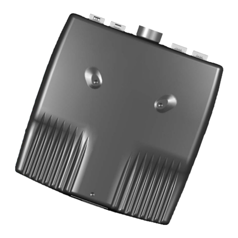
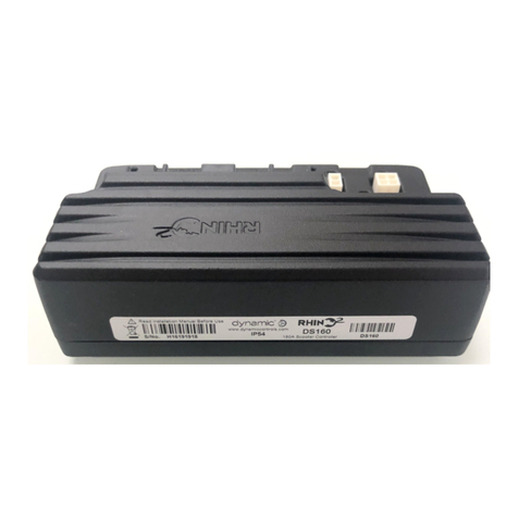
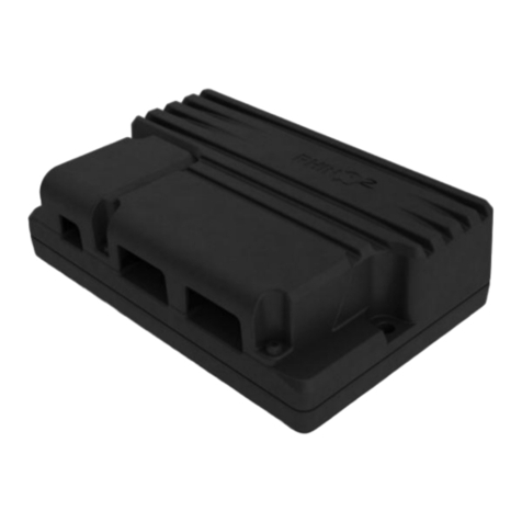
Figure 1: RHINO2 – DS90 and DS120 Figure 2: RHINO2 – DS160 and DS180
l90, 120, 160 and 180A models provide the power you want when you need it
lProgrammable acceleration curves, improved rollback on slopes, and improved
motor matching algorithms ensuring better curb-climbing and hill-starting
capabilities
lSpeed reduction wiper (SRW) technology provides a seamless speed reduction in
turns for extra stability
lThrottle Dual Decode (requires ISO compliant speed pot) provides extra safety in
case of a throttle failure.
lIntelligent motor and battery management providing automatic power flow
optimisation, auto battery configuration, 5 V and 12 V battery capacity outputs
(Trucharge) and in-depth battery logging and analysis tools
lSupport for a range of battery types, multifunction pins and flexible drive inhibits
lAdvanced diagnostics and servicing tools, including event and drive time logging, and
programmable servicing scheduler
l2 Drive profiles, brake and reverse lights, reversing beeper and electronic park brake
release
lIP54 ingress protection
lA separately available aluminium terminal cover provides increased protection to
IP55 when fitted
Page 8 - Introduction

lCompliant with EU Directive 2011/65/EU of 8 June 2011 – Restrictions on use of
Hazardous Substances (RoHS)
Note
Unless otherwise specified, all references in this manual apply to all variants of the RHINO2 controller.
Note
The RHINO2 controller conforms with global standards and is intended for both indoor and outdoor use.
GBK51948 RHINO2
Installation Manual Issue 5
Introduction - Page 9

GBK51948 RHINO2
Installation Manual Issue 5
Page 10 Page left blank intentionally

GBK51948 RHINO2
Installation Manual Issue 5
4.1 Electrical Specifications
Parameter Description
Compatible Battery
Supply 24 V supply, 2 x 12 V in series, circuit breaker protected
Compatible Motor 24 V DC permanent magnet type, typically rated 200-1000 watts.
Min Nominal Max Units
Operating Voltage ( Vbatt)See Note 1 18 24 32 V
Reverse Supply Voltage -32 V
Quiescent Current (idle) 80 mA
Quiescent Current (sleep) 1 mA
Quiescent Current (Key-Off) 1 mA
Charging Current 4 8 A (RMS)
Throttle Resistance (Pin 2 - Pin 8) 4 5 6 kΩ
Speed Limit Pot – Pin 9 (linear) 90 100 110 kΩ
Speed Reduction Wiper – Pin 4, 6 or 12 (log) 9 10 11 kΩ
Current Rating – DS90
lContinuous (@ 20°C ambient) 36 A
lPeak (180 seconds @ 20°C initial) See
warning below 90 A
lBoost Current 10 A
lBoosted Current 100 A
lBoost Time 10 s
Current Rating – DS120
lContinuous (@ 20°C ambient) 48 A
lPeak (180 seconds @ 20°C initial) See
warning below 120 A
lBoost Current 20 A
lBoosted Current 140 A
lBoost Time 10 s
Current Rating – DS160
lContinuous (@ 20°C ambient) 64 A
lPeak (180 seconds @ 20°C initial) See
warning below 160 A
lBoost Current 20 A
lBoosted Current 180 A
lBoost Time 10 s
Current Rating – DS180
lContinuous (@ 20°C ambient) 64 A
lPeak (60 seconds @ 20°C initial) See
warning below 180 A
Page 12 - Specifications

Parameter Description
Min Nominal Max Units
lBoost Current 20 A
lBoosted Current 200 A
lBoost Time 5 s
Park Brake Output
lVoltage 24 V
lCurrent 1.25 A
Note 1:
The RHINO2 transitions to Limp Mode when the battery voltage falls below its cut-off voltage or exceeds 30 V. During Limp
Mode, the scooter can continue to be driven, albeit at a reduced speed. If, while driving, the voltage drops below 17 V for more
than 4 seconds or rises above 33 V for more than 4 seconds, the scooter will slow down to a stop. Driving can resume once the
battery voltage is restored to within an acceptable voltage range, 21-29 V. If, while driving, the battery voltage rises to 35 V or
above, a slam stop will be invoked to prevent the battery being damaged.
Warning
The peak currents indicated above are based on when Stall Timeout is set to zero (that is, the stall timer is
disabled). The installer must ensure that the scooter’s wiring, connectors, and motor are suitable for these high
currents for this time period. The stall timer should never be disabled during normal operation.
GBK51948 RHINO2
Installation Manual Issue 5
Specifications - Page 13

GBK51948 RHINO2
Installation Manual Issue 5
4.2 Physical Specifications
Parameter Description
Aluminium Top, Base and Terminal cover Aluminium alloy ADC12
Protection Rating (with cover) Electronics rated to IP55
Protection Rating (without cover) Electronics rated to IP54
Shipping Weight:
Controller Unit
Terminal cover
DS90, 120, 160, 180
952 grams
55 grams
Min Nominal Max Units
Operating Temperature Range -25
-13
50
122
°C
°F
Storage Temperature Range -40
-40
65
150
°C
°F
Operating Humidity Range 0 90 %RH
Connector mating cycles‡1
lBattery 30
lMotor 30
lPark brake 30
lBattery charging and programming 30
lTiller 30
‡1 Connector descriptions / part numbers can be found in section 5 Installation and testing.
Figure 3: DS90 and DS120 variants Figure 4: DS160 and DS180 variants
For mounting hole dimensions, refer to Section 5.1 Mounting
Page 14 - Specifications

5 Installation and testing
5.1 Mounting 16
5.1.1 General Mounting Conditions 16
5.1.2 Mounting Orientation 17
5.2 Attaching the terminal cover 19
5.3 Connections and Wiring 20
5.3.1 General Wiring Recommendations 20
5.3.2 Wiring Diagram for DS90 and DS120 22
5.3.3 Wiring Diagram for DS160 and DS180 22
5.4 Battery Connections 23
5.5 Motor Connections 25
5.5.1 Motor Protection 26
5.5.2 Motor Testing 26
5.6 Park Brake Connections 27
5.6.1 Park Brake Testing 29
5.7 Battery Charging and Programming Connections 29
5.7.1 Battery charger connections 30
5.7.2 Programmer Connections 32
5.7.3 External Ambient Temperature Sensor Connection 33
5.8 Tiller Connector 34
5.9 Throttle Configuration 35
5.9.1 Protection against open-circuit, short-circuit and
leakage current 35
5.9.2 Single throttle wiper 36
5.9.3 Neutral Detect 37
5.9.4 Two throttle wipers - mirrored 40
5.9.5 Throttle Calibration 40
5.9.6 Speed Limit Pot Connections 41
5.9.7 Alternative Speed Reduction Options 42
5.9.8 Tiller Battery Supply 44
5.9.9 Key Switch Input 45
5.9.10 Status Indicator Output 45
5.9.11 Beeper Output 46
5.9.12 Battery Gauge Output 46
5.9.13 Brake and Reversing Lights 47
5.10 Multifunction Pins 48
5.10.1 Multifunction Inputs 48
5.10.2 Multifunction Outputs 50
5.11 Controller Power Modes 51
5.11.1 Powered Down 51
5.11.2 Normal Mode 51
5.11.3 Sleep Mode 52
5.11.4 Low Power Mode 52
5.12 Testing 54
GBK51948 RHINO2
Installation Manual Issue 5
Installation and testing - Page 15
Installation and testing

GBK51948 RHINO2
Installation Manual Issue 5
5.1 Mounting
5.1.1 General Mounting Conditions
Figure 5: RHINO2 Mounting Configuration
lThe position and orientation should give maximum mechanical protection to the
controller.
lMount out of the path of water splashes from wheels or cowling and protect the
connector panel from direct splashing.
lThe controller should be mounted under the scooter cover.
lFailure to adhere to the mounting conditions specified may lead to water ingress,
which could result in system malfunctions and long-term damage to the unit.
lFor peak performance, locate the controller so that air can flow over and around the
case, particularly if mounting in the tiller.
lA position close to the batteries and motor is recommended to reduce the length of
high-current wires.
lUse both screw positions to attach the controller. M5 cap screws are recommended.
Other M5 fasteners can also be used. Do not over tighten the mounting screws (max
8Nm).
lUse a magnetic tip screwdriver for removing and fitting fasteners.
lRefer to section 5.1.2 Mounting Orientation for recommended mounting orientations.
lIf an extension loom is fitted, mount it with the female connector facing horizontal or
downwards, and protect it from direct splashing. If the extension loom is to be used
for frequent disconnection, mount the female connector so that it faces downwards.
Warning
Regardless of mounting orientation, protect scooter wiring, connectors and components (including those of the
tiller head) from the risk of damage, water splashes and/or water ingress, and route the cabling so that water
will not run down into the connector system. Female connectors on extension cables should be mounted so that
they are horizontal or face downwards.
Do not mount the RHINO2 in a position where the user can come into contact with the unit. The case
temperature can exceed 41°C.
If cover accessory is used and product is mounted in an orientation that will allow water to pool, a drain or
drain holes (of 2.5 mm diameter) should be drilled in the cover.
Page 16 - Installation and testing

5.1.2 Mounting Orientation
Recommended mounting orientation
The recommended mounting orientations for RHINO2 units are vertical (with connector side
on the bottom) and horizontal (with connector facing upwards or downwards). The
horizontal (with connector facing downwards) mounting orientation is permitted to be tilted
a further 30° for mounting.
Figure 6: Vertical (Connector side on the bottom) Mounting Orientation
Figure 7: Horizontal (Connector facing upwards) Mounting Orientation
Figure 8: Horizontal (Connector facing downwards) Mounting Orientation
GBK51948 RHINO2
Installation Manual Issue 5
Installation and testing - Page 17

GBK51948 RHINO2
Installation Manual Issue 5
Mounting orientation to be avoided
The horizontally tilted mounting orientations and vertical (with connector side on the top)
orientation, which have chances of water and dirt accumulation, are not recommended.
Figure 9: Horizontally Tilted Mounting Orientations
Figure 10: Vertical (Connector side on the top) Mounting Orientation
Page 18 - Installation and testing
This manual suits for next models
3
Table of contents
Other Dynamic Controllers manuals
Popular Controllers manuals by other brands

BEA
BEA Two MC50s Interlocking 4 Doors Wiring diagram

Planet Networking & Communication
Planet Networking & Communication WAPC-500 Configuration guide

D&R ELECTRONICS
D&R ELECTRONICS FPC8TL-PIC Installation & operation manual

Ryobi
Ryobi One+ Easy Starter Original instructions

MICRO GROW
MICRO GROW GROWMASTER Installation procedures

Samson
Samson Type 5824 Mounting and operating instructions