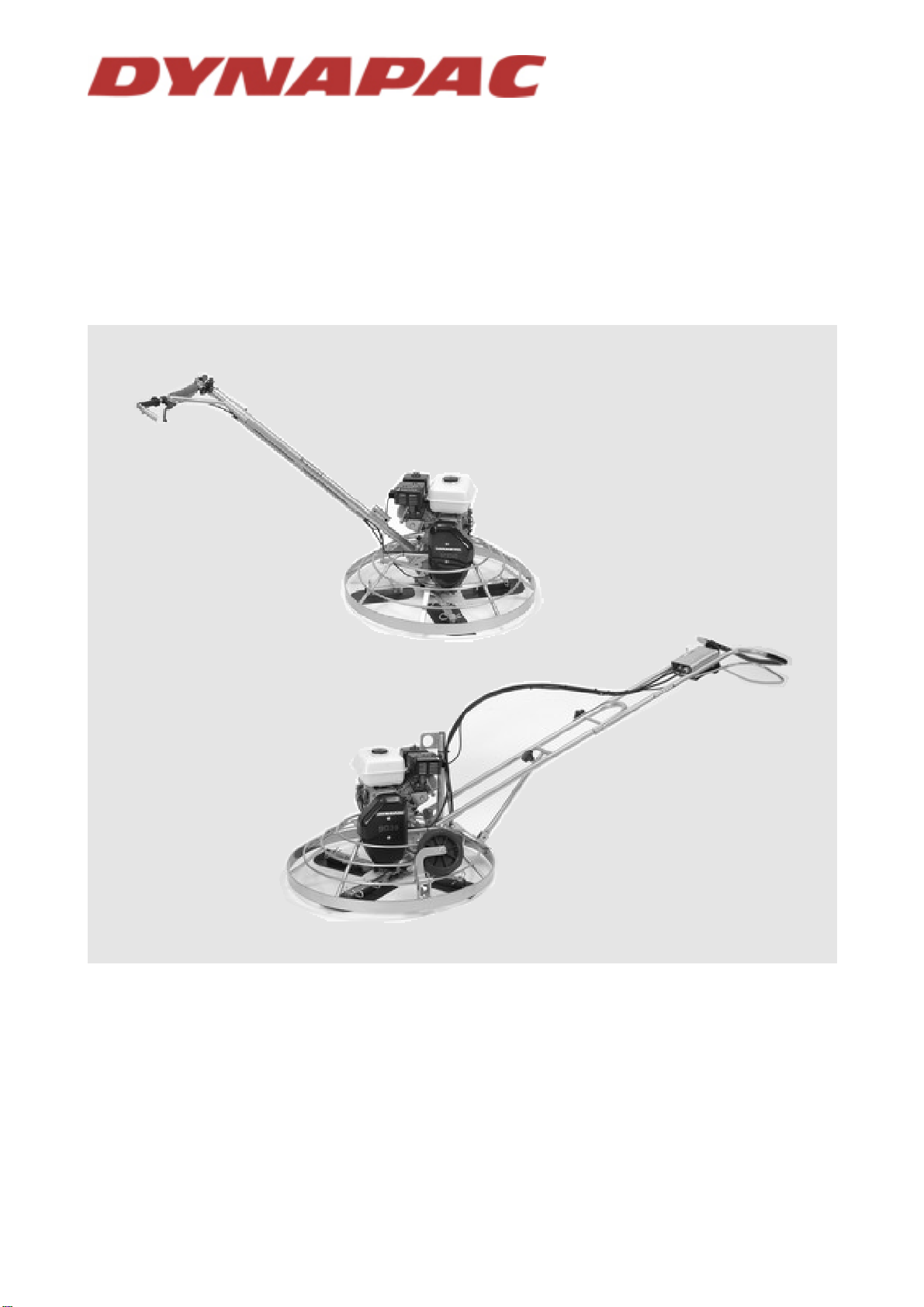
Dynapac BG49 Series Installer manual

CONCRETE EQUIPMENT
CONCRETE EQUIPMENTCONCRETE EQUIPMENT
CONCRETE EQUIPMENT
Manual number : 4700368349_ENG_NO.DOC
Revision :
BG49 Power Floats
Instructions and spare parts catalogue

INSTRUCTIONS – BG49
File: 4700368349_ENG_NO.doc Page 2 / 25 Original instructions
SUMMARY
GENERAL SAFETY RULES...............................................................................................3
Important rules for your safety ........................................................................................................................3
Safety equipment ............................................................................................................................................3
Working area...................................................................................................................................................3
Power supply...................................................................................................................................................4
Starting the machine .......................................................................................................................................4
Operation.........................................................................................................................................................4
Maintenance....................................................................................................................................................4
Be alert............................................................................................................................................................4
GENERAL ...........................................................................................................................5
DESIGN...............................................................................................................................5
TECHNICAL DATA .............................................................................................................5
ASSEMBLY INSTRUCTIONS.............................................................................................6
INSTALLATION OF OPERATING HANDLE...................................................................................................7
INSTALLATION OF BLADES .........................................................................................................................7
TEST...............................................................................................................................................................7
WORKSHOP TOOLS .....................................................................................................................................7
OPERATING INSTRUCTIONS............................................................................................8
BEFORE STARTING......................................................................................................................................8
STARTING......................................................................................................................................................8
STOPPING......................................................................................................................................................8
MAINTENANCE ..................................................................................................................8
DAILY..............................................................................................................................................................8
WEEKLY (50 hours)........................................................................................................................................8
SPARE PARTS CATALOGUE............................................................................................9
RANGE OF POWER FLOATS......................................................................................................................10
ACCESSORIES ............................................................................................................................................10
MAINTENANCE KITS...................................................................................................................................10
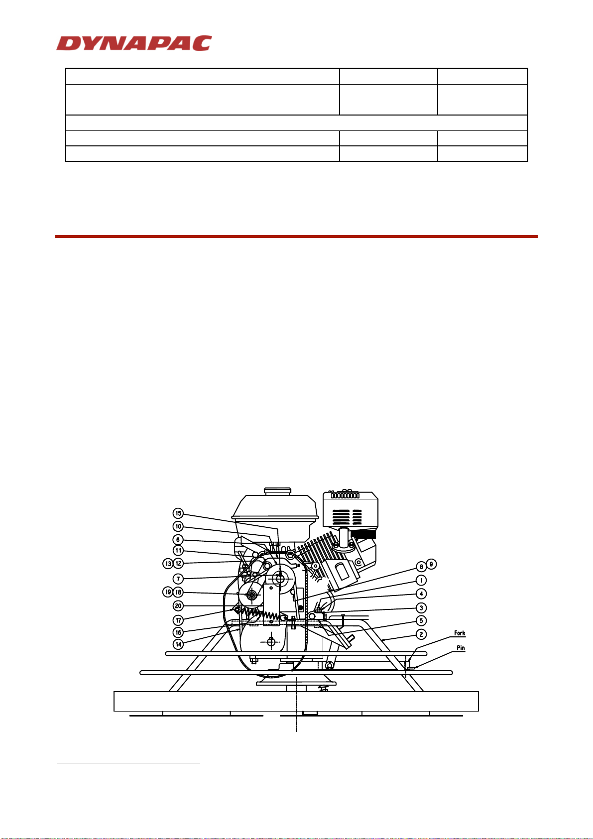
Engine and clutch..........................................................................................................................................11
Short handle..................................................................................................................................................13
Long handle...................................................................................................................................................15
Blades and guard ring...................................................................................................................................19
Gearbox ........................................................................................................................................................21

INSTRUCTIONS – BG49
File: 4700368349_ENG_NO.doc Page 3 / 25 Original instructions
GENERAL SAFETY RULES
Machines submitted
Powered with : Electric, Pneumatic, Petrol or Diesel engine.
Symbols
The words WARNING and CAUTION used in safety instructions, have the following meanings :
WARNING indicates hazards or hazardous procedures which could result in serious injury or death ,
if the WARNING is not observed.
CAUTION indicates hazards or hazardous procedures which could result in injury or damage to
equipment if the WARNING is not observed.
IMPORTANT RULES FOR YOUR SAFETY
WARNING
The machine must not be modified without prior consent of the manufacturer. Use only original parts.
If modifications are made without prior consent of the manufacturer there is a risk of serious injury to
the personal.
These safety recommendations have been compiled from international safety standards.
Local regulations must also be checked and observed. Before using the machine, read carefully
these instructions and keep them in a safe place.
Make sure that the signs about using, safety, and maintenance are always legible.
The use of the machine is restricted to the applications specified in the product literature.
Always change damaged parts immediately. Change wear parts in due time.
SAFETY EQUIPMENT
WARNING
The admissible sound level of 85 dB (A), can be exceeded because of the machine and/or the
application. Long time exposure to loud noise without ear protectors can cause permanent damage
to hearing.
Long time exposure to vibrations can damage the hands, fingers and wrists. Do not use the machine
if you are experiencing discomfort, cramp or pain. Consult a doctor before working again with the
machine.
Always use approved safety equipment. The following safety equipment applies to operators and
other personnel in the immediate vicinity of the working zone.
Safety helmet.
Ear protectors.
Dust mask in dusty environments.
Protective gloves.
Protective shoes.
Goggles.
To avoid the risk of clothes being caught in the machine, avoid wearing loose-lifting clothes. If you have long
hair, cover it with a hair net.
WORKING AREA
WARNING
Do not use the machine in explosive environments.
Do not operate a machine powered by a petrol or diesel engine in poorly ventilated spaces. These
types of engines produce toxic gases which can cause serious health troubles.

INSTRUCTIONS – BG49
File: 4700368349_ENG_NO.doc Page 4 / 25 Original instructions
POWER SUPPLY
WARNING
Make sure that the power supply equipment complies with the relevant safety requirements of the
local and the international standards.
- Electric machine: It must be ensured that the machine is connected to the voltage and the
frequency specified on the name plate. The power supply cable has to be properly sized. Check
that the cable and the plug of the machine are not damaged. Never switch off the machine by
pulling the plug from its socket. Use the machine switch. Keep the cable out of the moving parts
of the machine.
- Pneumatic machine: Check that the compressed-air hose and the hose coupling are not
damaged. Never attempt to loosen a compressed-air hose which is pressurized. First switch off
the air at the compressor and then leave the machine running itself to discharge the hose after
some seconds.
- Machine powered by petrol or diesel engine: Petrol has an extremely low flash-point and can
be explosive in certain situations. Keep away from all hot or spark-generating objects, do not
smoke, when handling fuel. Wait until the machine has cooled before filling the tank. Avoid
spilling petrol or diesel on the ground.
STARTING THE MACHINE
CAUTION
Before starting make yourself familiar with the machine and make sure that the machine does not
show any obvious faults. Then start the machine according the instruction and spare parts
catalogue.
OPERATION
CAUTION
Use the machine only for the purpose for which it is intended. Make sure you know how to stop the
machine quickly in the event of an emergency situation. Do not touch rotating parts during operation.
MAINTENANCE
CAUTION
Maintenance work must only be carried out by skilled personnel. Keep unauthorized persons away
from the machine. Do not carry out maintenance work while the machine is moving or the engine is
running. Never use a machine which is damaged.
BE ALERT
CAUTION
Always concentrate on what you are doing. Use common sense. Never operate the machine if you are
tired or under the influence of drugs alcohol or other substances which can affect your vision,
reaction, ability or judgement.

INSTRUCTIONS – BG49
File: 4700368349_ENG_NO.doc Page 5 / 25 Original instructions
GENERAL
The DYNAPAC BG49 is designed for rough and fine machine trowelling of concrete floor.
The original manual is in English.
DESIGN
The BG49 is driven by a four stroke petrol engine (1).
It is equipped with a dead-man handle (2) which stops the rotor as soon as it is released or if the operator
loose control of the operating handle (3).
The engine power is transmitted to the rotor supporting the blades (4) through a V belt clutch and a reduction
gear box (5). The blades are protected by a guard ring (6).
The blade control knob (7) provides an accurate and easy adjustment of the blade pitch.
The rotation speed of the blades should be adjusted by the throttle lever (8).
The engine stop is controlled by an ON-OFF switch (9) which avoids loosing the operating handle to stop the
engine.
The BG49 can be equipped of short or long operating handle.
1. Petrol engine.
2. Dead-man handle.
3. Operating handle.
4. Blades.
5. Reduction gear box.
6. Guard ring.
7. Control knob.
8. Throttle lever.
9. ON-OFF switch.
TECHNICAL DATA
BG49GS BG49GL
Total weight kg - (lb) 107 119
Rotor diameter mm - (in) 1140 - (44.80) 1140 - (44.80)
Blade speed (r.p.m.) 50 to 120 50 to 120
Number of blades 4
POWER UNIT
Engine brand HONDA
Model GX270 QX
Rated power kW - (hp) 6 - (8.0)
At (r.p.m.) 3 600
Fuel Gasoline
Gasoline tank capacity l - (gal) 6 - (1.60)
Noise level
1
LpA dB(A)
LwA dB(A) 93
104
1
measured in air at 1 m from the power floats dB(A) , according to ISO3744.

INSTRUCTIONS – BG49
File: 4700368349_ENG_NO.doc Page 6 / 25 Original instructions
BG49GS BG49GL
Vibration exposure
2
m/s
2
Uncertainty 5.97
0.50 3.16
OVERALL DIMENSIONS
L x w x h (mm) 2176x1196x1010 2796x1196x1010
(in) 85.4 x 47 x 39.8 110 x 47 x 39.8
IMPORTANT
The above information is a general description only, is not guaranteed and contains no warranties of
any kind.
ASSEMBLY INSTRUCTIONS
INSTALLATION OF ENGINE
Available for BG49 Kit (Without engine) P/N 4700368347 or for engine replacement. Equipped
to receive : HONDA GX270QX
1. Screw in place the four studs (1) on the base (2) (Screw driver 5 mm width). Use Loctite 243 or
equivalent.
2. Then put the engine in place and secure it with washers (3) and nuts (4) (17mm flat spanner).
3. Put in place the drive pulley (6) on the engine shaft without screwing the locking screw. Do not forget
the key (7).
4. Install the cover holder on the engine and tight it with screws (8) and washer (9) (13mm flat spanner).
5. Mount the complete lever (10) on the engine use 1 x washer (11) between the nut (12) and the engine.
6. Tighten the screw (13) and then secure it with nut (12) (2x13mm flat spanner) in order to let the
complete lever praticly free in rotation.
7. Put in place the V-belt (14) and tighten locking screws (15) in order to get the 3 x pulleys in line (3mm
Hexagonal spanner).
8. Hook the spring (16) to the guide screw (17).
9. When bending the V-belt by hand, using lever (10) the gap between guide screws and V-belt should be
approx.3 mm. If necessary adjust the gap with screw (18) and washer (19) (5mm Hexagonal spanner +
17mm flat spanner).
2
According to ISO5379

INSTRUCTIONS – BG49
File: 4700368349_ENG_NO.doc Page 7 / 25 Original instructions
10. Connect the cable 21 on the stop engine cable
and connect the cable 22 on the engine body.
INSTALLATION OF OPERATING HANDLE
•Take off the 4 x nuts and washers from the base. Then put in place the operating handle and secure
it with washers and nuts (17mm Flat spanner).
•Slide the electrical cable inside the protective tube of the operating handle and connect it to the
ON/OFF switch.
•Hook up the throttle cable for each particular engine (Cruciform screw driver). When throttle control is
fully pushed in, engine throttle control should be against idle adjustment stop. If adjustment in cable
length is necessary, make adjustment at handle end of the cable (3mm Screw driver).
•Dismantle the V-belt cover (10mm Flat spanner). Then slide the clutch cable through the adjusting
screw of the guard ring and through the tensioning lever hole . By hand let the tensioning lever bend
slightly the V-belt and then tighten the tensioning lever screw (3mm Screw driver). Ensure that when
the dead man handle is grip the V belt is normally tensioned and when it is released the V belt is not
tensioned.
•If necessary make adjustment of tensioning by the adjusting screws situated at each end of the
cable.
•Put in place the V-belt cover.
•Turn trowel control knob in a counter-clockwise direction until rotation is impossible. Take off the pin
from the fork, slide the cable into the fork and then secure it with the pin.
INSTALLATION OF BLADES
•Slip the blade in place on the trowel arm.
•Secure the blades with the spring clips supplied (2 per blades).
TEST
ALWAYS HAVE THE THROTTLE AT IDLE WHEN STARTING ENGINE
•Check engine oil level.
•Fill gasoline tank.
•Set ON/OFF switches on "ON" position (on engine and operating handle).
•Start the engine (see engine operating manual) and if necessary adjust throttle cable and clutch
cable for proper operation.
•Set the engine to 3000 rpm (see engine instruction manual).
WORKSHOP TOOLS
•1x Screw driver 5 mm width.
•1x 10mm Flat spanner.
•1x 17mm Flat spanner.
•2x 13mm Flat spanner.
•1x 3mm Hexagonal spanner.
•1x 5mm Hexagonal spanner.
•1x Screw driver 3 mm width.
•1x Cruciform screw driver.

INSTRUCTIONS – BG49
File: 4700368349_ENG_NO.doc Page 8 / 25 Original instructions
OPERATING INSTRUCTIONS
CAUTION
Keep clear of rotating parts when operating.
Always have throttle position at idle when starting engine.
Never lift by the guard-ring
Remove smoothing disc before lifting.
Always test dead-man handle for proper operation before beginning.
Never refuel while running or while engine is hot
Refuel in well ventilated area, away from sparks, and open flame.
Always disconnect spark plug before servicing.
Always disconnect the power supply before servicing
BEFORE STARTING
ALWAYS HAVE THE THROTTLE AT IDLE WHEN STARTING ENGINE
•Check engine oil level.
•Fill gasoline tank.
•Make sure that all blades are at the same angle. If necessary adjust the blade angle.
STARTING
•Turn the fuel valve "ON".
•Set ON/OFF switches on "ON" position.
•Close choke located on the engine only if the engine is cold.
•After the engine starts open choke for smooth running and let the engine warm up for two or three
minutes at idle speed. Adjust the throttle at desired speed and then clamp slowly the dead man
handle in order to start the blades rotating.
STOPPING
•Release the dead man handle.
•Set throttle at idle speed.
•Set the ON/OFF switch to "OFF" position.
MAINTENANCE
DAILY
Clean cement from machine.
Check engine oil level. Add oil as needed to reach up the maximum level.
Do not overfill. Refer to the engine instruction book.
Clean air filter foam cover.
Check blade pitch adjustment for proper operation.
Check "ON-Off" switch and dead man handle for proper operation.
WEEKLY (50 HOURS)
Check blades for excessive wear. If necessary reverse or replace blades.
Change engine oil. Refer to the engine instruction book.
Grease the blade arms (4 grease nipples) with SHELL Retinax HD grease or equivalent.
Check gear box oil level. Add oil as needed to reach up the maximum level. OIL MOBIL SHC634.

INSTRUCTIONS – BG49
File: 4700368349_ENG_NO.doc Page 9 / 25 Original instructions
SPARE PARTS CATALOGUE
RESERVDELSTÄLLNING
Följande uppgifter ska lämmas vid beställning av
reservdelar för att undvika leveransfel :
1. Maskintyp.
2. Maskinens seriunmmer.
3. Antal av önskad reservdel.
4. Reserdelens artikelnummer.
5. Reservedelens benämning.
6. Måttupgifter vid beställning av metervara.
ORDERING SPARE PARTS
To avoid errors in delivery, please give the following
information when ordering spare parts :
1. Type of machine.
2. Machine serial number.
3. Quantity required.
4. Part number.
5. Parts description.
6. Dimensions when ordering per length.
ERSATZTEILBESTELLUNG
Zur Vermeidung von Fehllieferungen sind bei der
Bestellung von Ersatzteilen folgende Angaben zu
machen :
1. Mashinentyp.
2. Herstellungsnummer.
3. Bestellmenge. (Quantity)
4. Ersatzteilbenennung. (Part N°)
5. Ersatzteilbenennung. (Description)
6. Massangaben bei Bestellung von Meterware.
ORDINI DI RICAMBI
Per evitare errori nelle consegne di ricambi, Vi
preghiamo di comunicarci le seguenti informazioni al
momento dell ‘ordinazione :
1. Tipo di macchina.
2. Numero di serie della macchina.
3. Quantitá dei pezzi desiderati. (Quantity)
4. Numero di codice del pezzo. (Part N°)
5. Descrizione del pezzo di ricambio. (Description)
6. Misura, in caso di ordine per metro.
PEDIDO DE RECAMBIOS
Para evitar errores en las entregas, deberá indicarse
los siguientes datos al hacer un pedido de
recambios :
1. Tipo de máquina.
2. Número de serie.
3. Cantidad de piezas deseadas. (Quantity)
4. Número de artículo de la pieza de recambio. (Part
N°)
5. Denominación de la pieza. (Description)
6. Indíquese la medida al solicitar un artículo que se
expide por metros.
COMMANDE DE PIECES DE RECHANGE
Les indications suivantes doivent être fournies lors
de la commande de pièces de rechange, afin d’éviter
toute erreur de livraison :
1. Type de machine.
2. Numéro de série.
3. Quantité désirée de pièce de rechange. (Quantity)
4. Numéro de la pièce de rechange. (Part N°)
5. Description de la pièce de rechange. (Description)
6. Longueur en cas de commande par mètre.

INSTRUCTIONS – BG49
File: 4700368349_ENG_NO.doc Page 0 / 25 Original instructions
SPARE PARTS
Note : To place spare part order, use :
- The serial number of the machine
- The description and the part number
RANGE OF POWER FLOATS
Type Engine brand Order
numbers Description
BG49GS HONDA 4700368344 DYNAPAC Blade arms
BG49GL HONDA 4700368295 DYNAPAC Blade arms
BG49GS HONDA 4700368345 Hexagonal blade arms
ACCESSORIES
Description BG49
P/N 4700368344
P/N 4700368295
BG49
P/N 4700368345
Set of 4 blades 4700702752 4700365553
Spring clips (8 per machine) 4700702681 -
Smoothing disc 4700365276 4700365276
Lifting eye 4700368354 4700368354
MAINTENANCE KITS
SPARE PARTS IN THE
MAINTENANCE KITS BG49 GS
P/N 4700368437 BG49 GL
P/N 4700368438
Clutch cable 4700365537 4700368394
Throttle cable 4700368103 4700368393
Blade angle cable 4700365536 4700368395
V-belt (2) 4700365516 4700365516
Dead-man handle 4700363518 -
Spark plug 4700361242 4700361242
Air filter element 4700361266 4700361266
Air filter foam 4700361267 4700361267
Carburettor gasket set 4700361272 4700361272

INSTRUCTIONS – BG49
File: 4700368349_ENG_NO.doc Page / 25 Original instructions
ENGINE AND CLUTCH
BG49GS BG49GL
Ref.
Description P/N Qty P/N Qty
1 Lever 4700365507 1 4700365507 1
2 Spacer 4700363490 1 4700363490 1
3 Pulley 4700365508 1 4700365508 1
4 Pulley 4700365510 1 4700365510 1
5 Nut 4700182119 1 4700182119 1
6 Engine HONDA 4700363330 1 4700363330 1
7 Cover holder 4700365533 1 4700365533 1
8 Bearing 4700363511 1 4700363511 1
9 Screw 4700508074 1 4700508074 1
10 Retaining ring 4700100322 1 4700100322 1
11 Screw 4700516002 1 4700516002 1
12 Screw 4700503013 1 4700503013 1
13 Washer 4700180918 4 4700180918 4
14 Nut 4700363512 1 4700363512 1
15 Nut 4700500029 4 4700500029 4
16 Washer 4700615044 4 4700615044 4
17 V-belt 4700365516 1 4700365516 1
18 Spring 4700363534 1 4700363534 1
19 Cover 4700365519 1 4700365519 1
21 Belt guide 4700365520 2 4700365520 2
22 Screw 4700500171 2 4700500171 2
23 Nut 4700570004 5 4700570004 5
24 Screw 4700503010 2 4700503010 2
25 Screw 0147300034 2 0147300034 2
27 Washer 4700600006 2 4700600006 2
28 Screw 4700187171 1 4700187171 1
29 Screw 4700533024 1 4700533024 1
30 Key - - - -
31 Dynapac Decal 4700704500 1 4700704500 1
32 Model Decal 4700368310 1 4700368310 1

INSTRUCTIONS – BG49
File: 4700368349_ENG_NO.doc Page 2 / 25 Original instructions

INSTRUCTIONS – BG49
File: 4700368349_ENG_NO.doc Page 3 / 25 Original instructions
SHORT HANDLE
BG49GS
Ref.
Description P/N Qty
1 Handle holder 4700363492 1
2 Cable tensionner 4700363493 1
3 Pulley 4700363494 1
4 Shaft 4700363495 1
5 Operating handle 4700368327 1
6 Sleeve 4700363500 1
7 Pin 4700110682 1
8 Screw 4700363501 3
9 Washer 4700600007 3
10 Screw 4700363502 1
11 Cable stop 4700363503 1
12 Screw 4700185920 2
13 Blade angle cable 4700365536 1
14 Handle 4700363505 1
15 Handle 4700363506 1
16 Pin 4700630007 2
17 Washer 4700604007 4
18 Nut 4700586018 4
19 Clutch cable 4700365537 1
20 Dead man handle 4700363518 1
21 Cable stop 4700363519 1
22 Throttle cable 4700368103 1
23 Throttle lever * 4700368434 1
24 Screw 4700541537 2
25 Expanding screw 4700364762 1
26 Handle holder 4700364758 1
27 Screw 4700500026 1
28 Screw 4700533034 1
29 Nut 4700586001 1
30 Handle 4700364759 1
31 Handle 4700364757 1
32 Cable shoe 4700185645 2
33 On/Off switch 4700364763 1
34 On/Off plate 4700365538 1
35 Membrane 4700364765 1
36 Sealing washer 4700364766 1
37 Cable 4700364119 2m
38 Belly cushion 4700365495 1
39 Dynapac Decal 4700360599 1
40 Decal 4700365464 1
41 Option : Lifting eye cpl. 4700368354 1
42 Nipple * 4700368433 1
43 Holder 4700368101 1
44 Decal 4700368102 1
45 Screw 4700100145 1
* Kit complete throttle lever : P/N 117268

INSTRUCTIONS – BG49
File: 4700368349_ENG_NO.doc Page 4 / 25 Original instructions

INSTRUCTIONS – BG49
File: 4700368349_ENG_NO.doc Page 5 / 25 Original instructions
LONG HANDLE
BG49GL
Ref.
Description P/N Qty
1 Screw 4700100145 2
2 Screw 4700100146 2
3 Sleeve 4700110035 1
4 Pin 4700110682 1
5 Retaining ring 4700152014 1
6 Cable stop 4700182174 1
7 Nut 4700183652 1
8 Gland 4700184307 1
9 Terminal 4700185645 2
10 Handle 4700312087 1
11 Plug 4700360531 1
12 Handle 4700363505 1
13 Switch 4700364763 1
14 Membrane 4700364765 1
15 Washer 4700364766 1
16 ON/OFF plate 4700365538 1
17 Sleeve 4700367157 1
18 Cable 4700367165 1
19 Decal 4700368312 1
20 Pipe 4700368365 1
21 Stay upper 4700368366 1
22 Stay lower 4700368367 1
23 Dead man handle 4700368372 1
24 Handle holder 4700368424 1
25 Holder 4700368385 1
26 Base 4700368386 1
27 Cover 4700368387 1
28 Screw 4700368388 1
29 Cover 4700368389 1
30 Screw 4700368390 1
31 Nut 4700368391 1
32 Bracket 4700368392 1
33 Throttle cable 4700368393 1
34 Clutch cable 4700117235 1
35 Blade angle cable 4700368395 1
36 Shaft 4700368396 1
37 Sleeve 4700368398 1
38 Plate 4700368399 1
39 Lifting eye 4700368429 1
40 Lower handle 4700368405 1
41 Spacer 4700368406 1
42 Box 4700368407 1
43 Shaft upper 4700368408 1
44 Screw 4700500013 1
45 Screw 4700500029 1
46 Screw 4700500030 2
47 Screw 4700500043 2
48 Screw 4700500088 2
49 Screw 4700500091 2

INSTRUCTIONS – BG49
File: 4700368349_ENG_NO.doc Page 6 / 25 Original instructions
BG49GL
Ref.
Description P/N Qty
50 Screw 4700533025 4
51 Screw 4700533027 4
52 Screw 4700533079 4
53 Screw 4700541409 8
54 Nut 4700586018 5
55 Washer 4700600004 2
56 Washer 4700600006 1
57 Washer 4700600008 3
58 Washer 4700604007 2
59 Washer 4700606002 4
60 Pin 4700629109 3
61 Screw 4700702618 1
62 Handle 4700702627 1
63 Clamp 4700702673 2
64 Stay 4700702788 1
65 Terminal 4700960066 2
66 Throttle lever 4700368434 1
67 Nipple 4700368433 1

INSTRUCTIONS – BG49
File: 4700368349_ENG_NO.doc Page 7 / 25 Original instructions

INSTRUCTIONS – BG49
File: 4700368349_ENG_NO.doc Page 8 / 25 Original instructions

INSTRUCTIONS – BG49
File: 4700368349_ENG_NO.doc Page 9 / 25 Original instructions
BLADES AND GUARD RING
BG49GS
P/N 4700368344
P/N 4700368345
BG49GL
P/N 4700368295
Ref.
Description P/N Qty P/N Qty
1 Shaft 4700363495 1 4700363495 1
2 Fork 4700365493 1 4700365493 1
3 Pulley 4700365509 1 4700365509 1
4 Nut 4700182119 1 4700182119 1
5 Pin 4700635002 1 4700635002 1
6 Pin 4700630007 2 4700630007 2
7 Bearing 4700182322 1 4700182322 1
8 Cup 4700182314 1 4700182314 1
9 Plate 4700368329 1 4700368329 1
10 Screw 4700500035 1 4700500035 1
11 Washer 4700603008 1 4700603008 1
12 Hub 4700363507 1 4700363507 1
13 Screw 4700182122 4 4700182122 4
14 Screw 4700185912 4 4700185912 4
15 Nut 4700573008 4 4700573008 4
16 Grease nipple 4700363510 4 4700363510 4
17 Cable stop 4700182174 1 4700182174 1
18 Screw 4700516002 1 4700516002 1
19 Bolt 4700365511 4 4700365511 4
20 Washer 4700365512 4 4700365512 4
21 Screw 4700365513 4 4700365513 4
22 Nut 4700586018 4 4700586018 4
23 Guard ring 4700368326 1 4700368326 1
Dynapac balde shaft 4700365515 4 4700365515 4
24 Hexagonal blade shaft 4700365545 4 -
Pin 4700702681 8 4700702681 8
25 Screw 4700500023 8 -
Dynapac blade 4700702751 4 4700702751 4
26 Bolt-on blade 4700365547 4 -
27 Gear box 4700365517 1 4700365517 1
28 Spring holder 4700363535 1 4700363535 1
29 Washer 4700600007 2 4700600007 2
30 Holder 4700365522 2 4700365522 2
31 Washer 4700604005 8 -

INSTRUCTIONS – BG49
File: 4700368349_ENG_NO.doc Page 20 / 25 Original instructions
Other manuals for BG49 Series
1
This manual suits for next models
2
Table of contents
Other Dynapac Trowel manuals
Popular Trowel manuals by other brands

Bartell
Bartell BC90 Owner's manual and parts book

BOMAX
BOMAX BM436 Operation manual

MBW
MBW SCREEDEMON WS500 Operator's safety and service manual

MULTIQUIP
MULTIQUIP Whiteman Series Operation manual

MULTIQUIP
MULTIQUIP Whiteman Series Operation and parts manual

Bartell Global
Bartell Global TS78 owner's manual