Dynaset HPW1200/100-440 User manual

HIGH PRESSURE PUMP HPW 1200/100-440
March 2013 JLe
1
HPW1200/100-440
HYDRAULIC HIGH PRESSURE WATER PUMP
OPERATING INSTRUCTIONS
Applications: abrasive power washing, street-cleaning, water cutting,
hydro demolition and scaling, water hydraulics, robotic washing,
pressure testing, offshore and underwater works, etc.
Dynaset HPW pump gives great waterpower with the best power to
weight ratio in the World.
Small size, lightweight, outstanding durable construction with
ingenious piston-to-piston action and low water consumption make
the hydraulic high-pressure water pump very cost effective.
HYDRAULIC FLOW l/min (gal min) max. 440 (116)
HYDRAULIC PRESSURE bar (psi) max. 300 (4350)
WATER DISCHARGE l/min (gal min) max. 100 (26,5)
WATER PRESSURE bar (psi) max. 1200 (17400)
WEIGHT kg (lb) 177 (390)

2
Operating with DYNASET HPW high-pressure pump user has to conform to all safety regulations concerning
pressurized equipment. Hydraulic circuit has a high-pressure over 350 bar (5077 psi).
EQUIPMENT TECHNICAL CONDITION HAS TO PAY SPECIAL ATTENTION.
In order to avoid accidents all operators and maintenance personnel must act in compliance with the laws,
regulations and recommendations the high pressure hydraulics, electricity and work safety issued by local
authorities.
EXTERME CLEANLINESS MUST BE MAINTAINED WHEN CARRYING OUT ANY DISSASSEMBLING OR
REPAIR OF HPW-UNIT AND HYDRAULIC SYSTEM. THIS IS CRUCIAL TO ENSURE SAFE, RELIABLE AND
LONG-LIFE OPERATION OF YOUR EQUIPMENT.
The pressure in hydraulic fluid circuit is considerably high and hydraulic system has to maintain regularly.
Especially couplings, valves and hoses have to be tight and clean as well as kept under constant observation.
Check and fix possible leakages of pressure and hot blowouts immediately avoiding user and bystander injuries.
In order to exclude possible accidents, it is not allowed to clean or inspect HPW unit when hydraulic fluid circuit
is pressurized. Prior to any cleaning, inspection and service hydraulic system of your carrier machine must be
stopped and all hydraulic fluid circuits depressurized.
Wear appropriate clothing and safety equipment such as goggles, ear and eye protection, safety shoes at all
times when operating by the HPW pump. Beware of machinery parts are warm by hot hydraulic oil.
Operators and maintenance personnel must always comply with local safety regulations and precautions in
order to close out the possibility of damages and accidents.
All installation and service hydraulic and electric equipment must be performing experienced personnel only.
Preventing freezing nozzles, water circuit and pipeline. Draining and air flushing have to perform
before ambient temperature reaches 0°C (32°F) or lower.
SAFETY PRECATIONS
WARNING STICKERS
Dynaset dispatch department includes one (1) warning sticker bag per one (1) main product.
Product recipient is obligated to fix determinate warning sticker to Dynaset product.
Attach sticker to visible and appropriate place or close to Dynaset product where it’s easily seen.
Before attaching sticker, clean surface with solvent detergent.
READ OPERATING INSTRUCTIONS. BEWARE OF HIGH PRESSURE KEEP FROM FREEZING. USE EAR PROTECTOR AND
SPLATTERS. GLOGGLES.
HIGH PRESSURE PUMP HPW 1200/100-440
March 2013 JLe

HIGH PRESSURE PUMP HPW 1200/100-440 OUTLINE DIMENSIONS
WP
FLUID CONNECTIONS
HYDRAULIC PORTS PUMPING FLUID PORTS
pressure return pressure intake
P T CMP WP S WMP
SAE 6000 SAE 6000 DIN MP *SAE 3000 HP *
1 1/4” 1 1/4” R1/8” 3/4” 2” 1/4”
110 mm
(4 3/10”)
915 mm (2’ 11 8/10”)
350 mm
(1’ 1 8/10”)
265 mm
(10 4/10”)
8 pcs. Ø 16 mm (6/10”)
15 mm
(6/10”)
835 mm (2’ 8 9/10”)
70 mm (2 8/10”)
194mm /
0,636”
630 mm (2’ 8/10”)
PT
S
CMP
WMP
3
HIGH PRESSURE PUMP HPW 1200/100-440
*MORE INFORMATION
ON PAGE 10.
March 2013 JLe

DYNASET HIGH PRESSURE PUMP HPW 1200/100-440 -pump is compact and integrated all-in-one units,
designed for both mobile and workshop installation. HPW-pumps perfectly work installed on excavators, mining
machines, tractors, trucks and vans. In workshop use, HPW-pump is accompanied with hydraulic aggregate.
DYNASET HPW-pump can be positioned deliberately, keeping in view following preconditions:
1. Easy service access to the unit should be ensured.
2. Pump should be mounted on sufficiently horizontal surface to enable proper working of leakage detecting
bores, which are found above and below seal disc the surface, see blue arrows. We recommended to using
eight (8) bolts to secure reliable fastening. Leakage detecting bores are made to the zones, which separate oil
and water chambers from each other.
If the draining from leakage detectors exceeds rate of 10 drops per minute, pump sealing’s should be replaced.
The drain fluid can be water, hydraulic oil or their solution.
INSTALLATION
4
Lower leakage detecting bores
LEAKAGE DETECTING BORES
GENERAL
Bottom view.
Inlet manifold removed
HIGH PRESSURE PUMP HPW 1200/100-440
March 2013 JLe
HPW-pump is to be connected to hydraulic system of carrier machine, as well as to pumping fluid circuit.
HPW can be installed with no particular efforts to system based on either constant or variable displacement
hydraulic pump, as well as to closed hydraulic systems.
1. HYDRAULIC SYSTEM WITH CONSTANT DISPLACEMENT PUMP:
The required oil flow is set by correct dimensioning of the hydraulic pump and keeping the demanded
rotation speed or, alternatively, with pressure compensated 3-way valve.
2. HYDRAULIC SYSTEM WITH VARIABLE DISPLACEMENT PUMP:
A. In system with OPEN CENTRE the required oil flow is set by DYNASET PRESSURE COMPENSATED
PRIORITY VALVE
B. In system with CLOSED CENTRE (load sensing system) the required oil flow is set by
DYNASET LS-VALVE kit, which comprises solenoid valve, pressure compensated oil flow limiter
and pressure relief valve.
INTEGRATION INTO A HYDRAULIC CIRCUIT

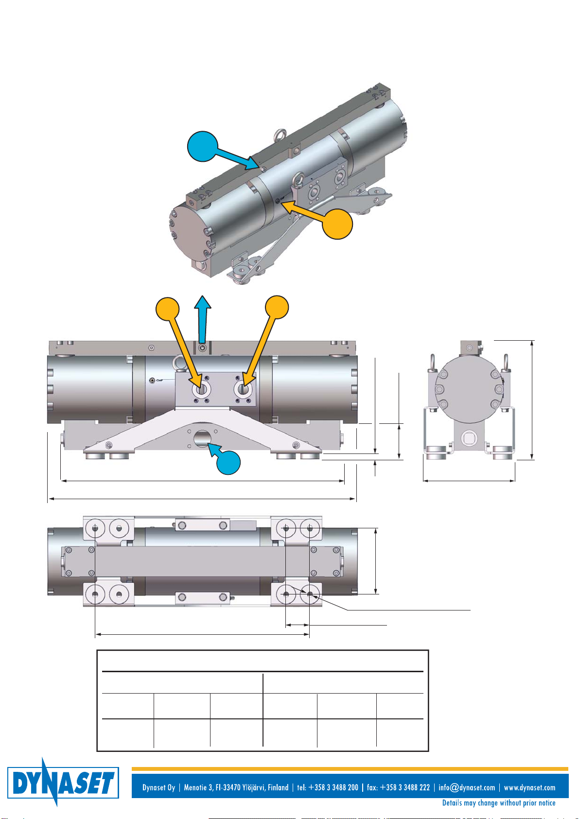
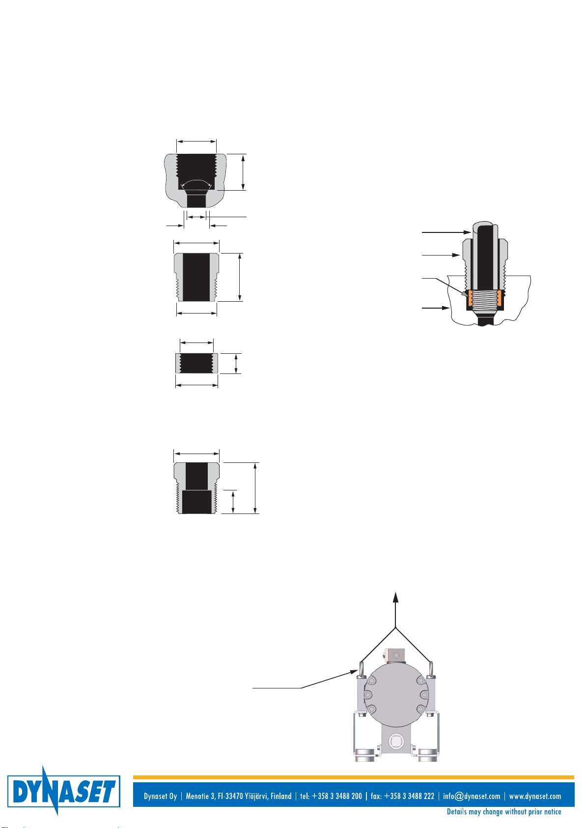
To ensure secure installation use in hydraulic ports SAE 6000 1 1/4” flanges. Use in pressure port MP 3/4“
fitting and in water intake SAE 3000 2” flange.
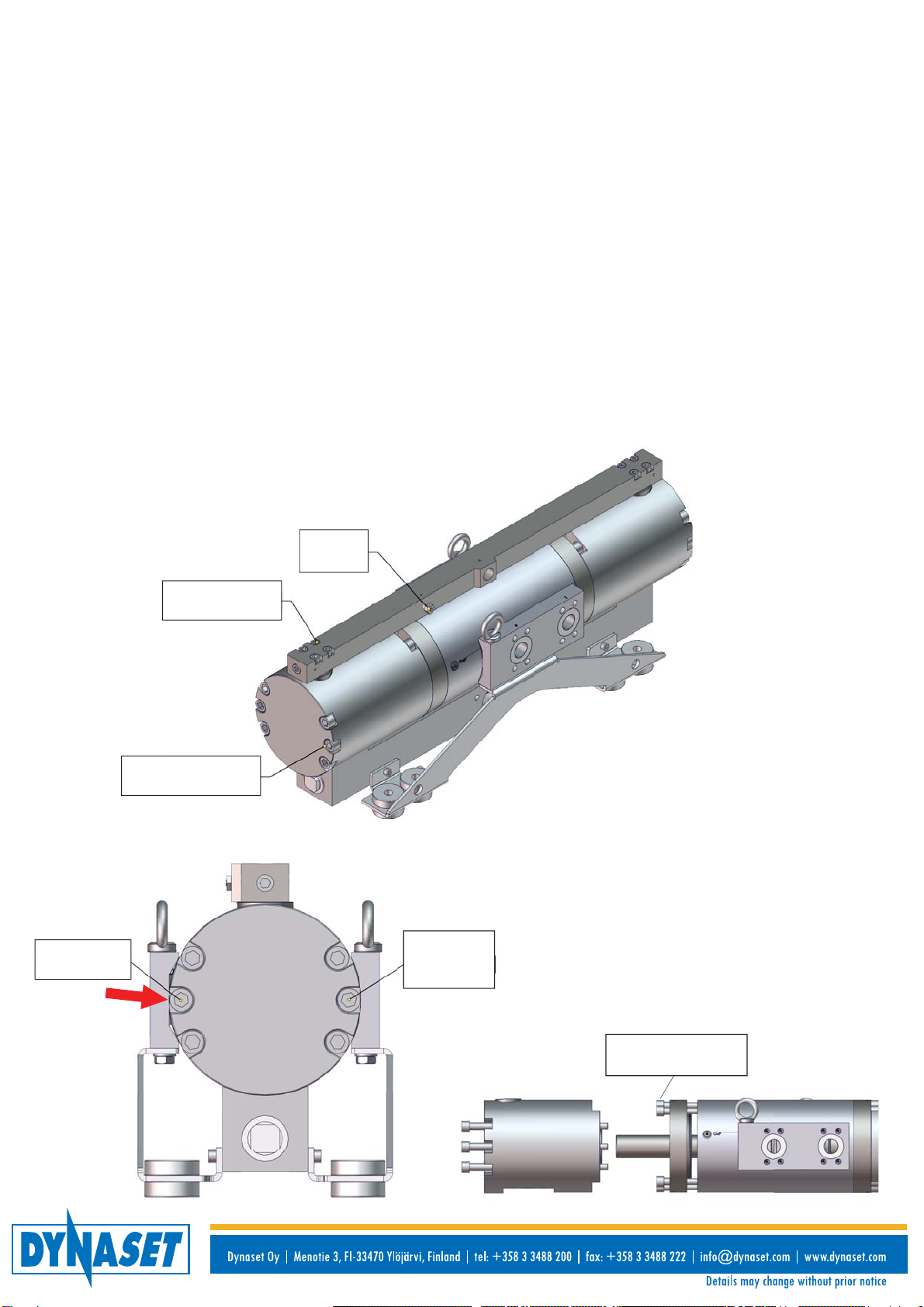
Recommended bolt torques on assembly.
- Water head left six (6) bolts 16x300 mm 300 Nm (221 ft-lb)
- Water head right five (5) bolts 16x300 mm 300 Nm (221 ft-lb), front middle near tank line 1 bolt 16x300 mm
200 Nm (148 ft-lb) red arrow, see next page).
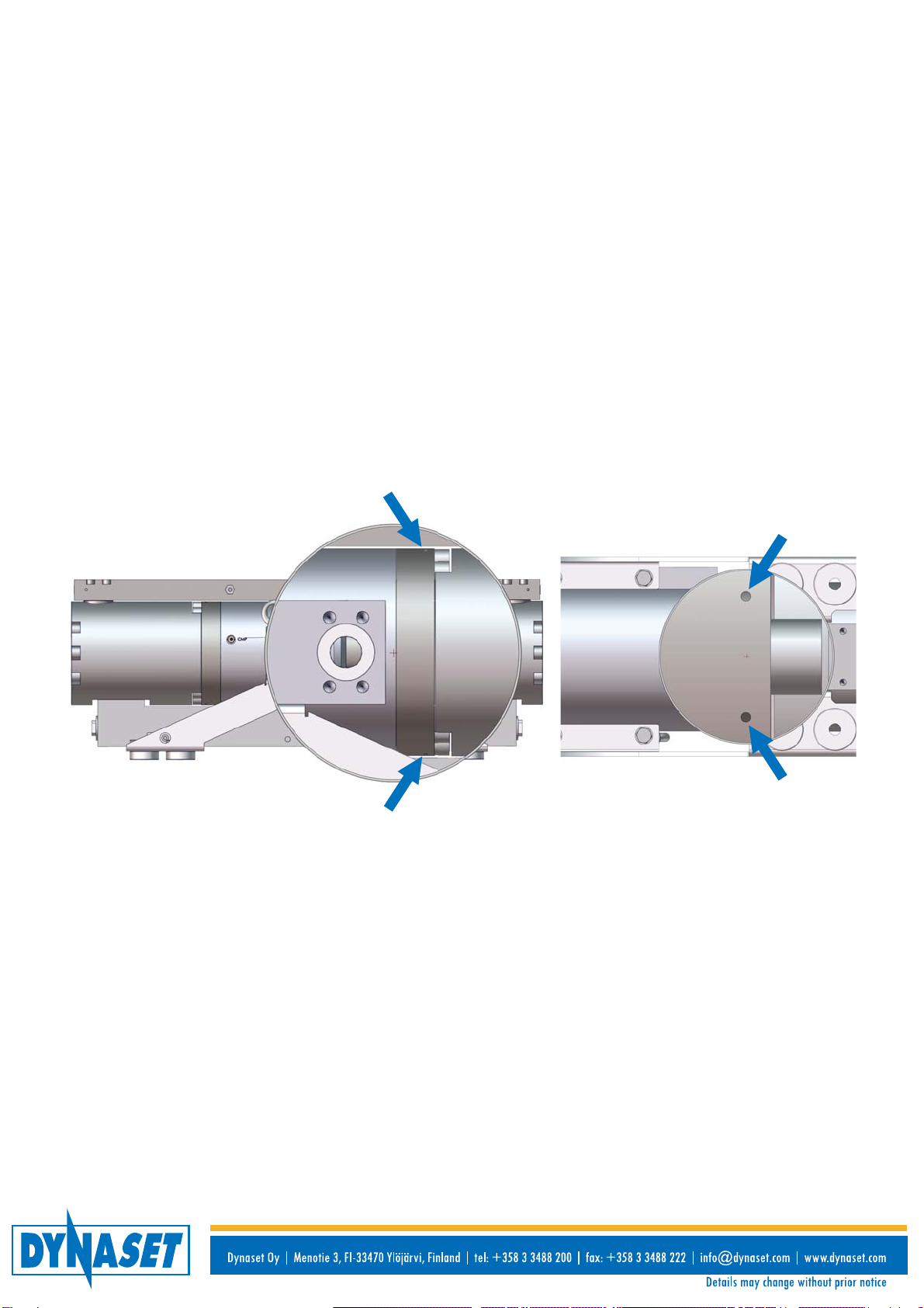
- Seal flange 2 psc. six (6) bolts 16x75 mm 335 Nm (247 ft-lb).
CONNECTIONS
5
1. Pressure and flow in pumping fluid circuit are adjusted by adjusting corresponding parameters in hydraulic
circuit.
2. In circuits based on constant displacement pump closing the water pressure line opens the pressure relief
valve in hydraulic system. PAY ATTENTION THAT HYDRAULIC FLUID CIRCULATION THROUGH
PRESSURE RELIEF VALVE CAUSES HEATING OF HYDRAULIC SYSTEM!
3. In circuits based on variable displacement hydraulic pump closing the water pressure line adjusts pump’s
swash plate at 0° angle when hydraulic pump produces flow only for self-lubrication and self-flushing.
Pressure control must be fast enough to protect HPW-pump from pressure peaks or the hydraulic system
must be provided with pressure peak limiter.
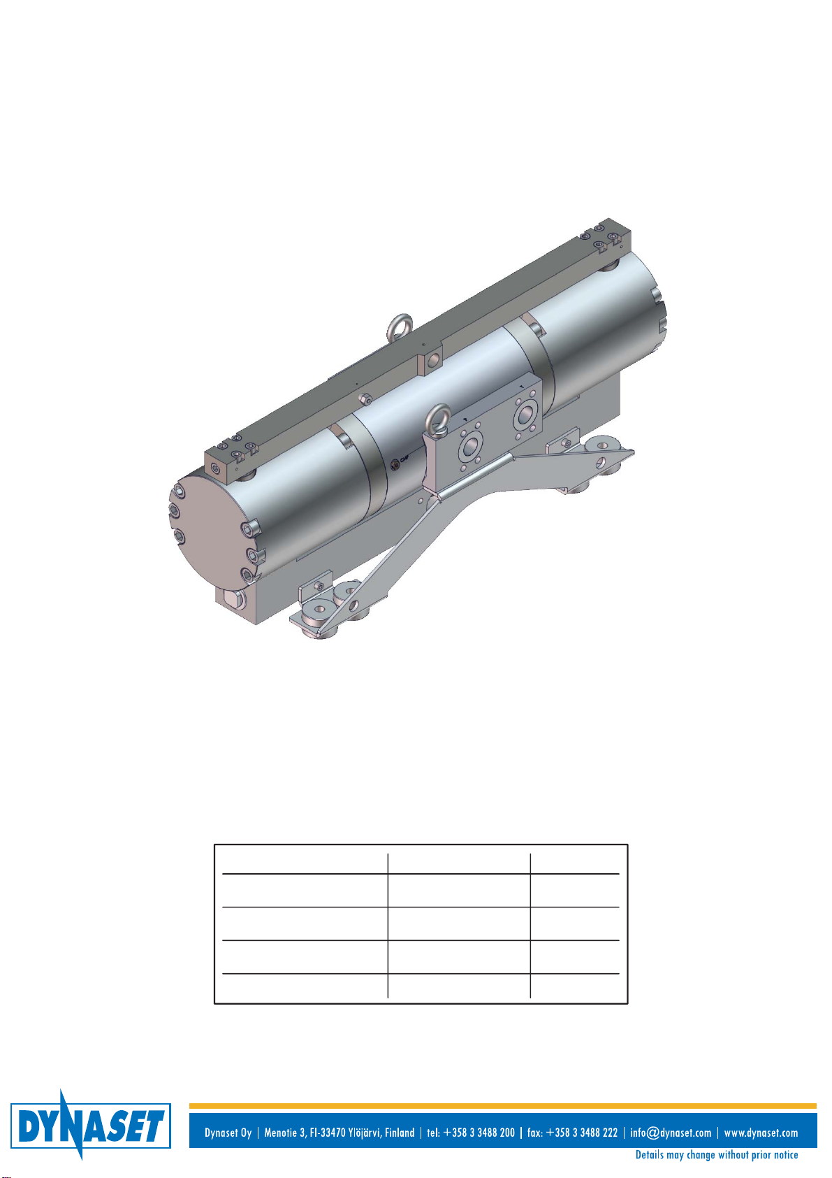
INSTALLATION
HIGH PRESSURE PUMP HPW 1200/100-440
March 2013 JLe
PUMP START-UP
HPW-pump starts immediately after the hydraulic flow has been put on either with control valve (manual or
solenoid) and/or by pulling the trigger of spray gun.
Immediately after opening the water pressure line, air is being vented out from the pumping fluid circuit and
high-pressure washing is about to begin!
DO NOT TRY WITH HAND THE WATER OR AIR COMING OUT FROM HIGH PRESSURE NOZZLE!
The nozzle, attached to a pressure tool, determines the flow rate and pressure of water when operating
parameters of hydraulic circuit meet HPW-pump’s requirements.
In other words, even your HPW-pump fits perfectly to hydraulic system and does well with the job, dimensioning
of the pressure tool should never be underestimated as a very important step for ensuring the optimal water jet
or hydro-demolition power in each application.
ADJUSTING FLOW RATE AND PRESSURE OF PUMPING FLUID
ATTENTION !
Check the ports of your HPW-pump and connect it to hydraulic and pumping fluid circuits according to their
markings !
1. If the hydraulic pressure line will be connected by accident to the return port and return line
correspondingly to the pressure port, it will not cause any harm to HPW-pump, however pump will not
operate.
2. Output power of HPW-pump depends on the pressure difference between pressure and return lines.
The more is the pressure in return line, the less is concerned pressure difference and output power of the
pump. The fact should be taken into account when certain number of machines are intended to be joined-up
in series.
3. Since the piston assembly reverses extremely rapidly (refer to the TECHNICAL SPECIFICATIONS), certain
oscillation can be imposed to the return line because of pressure pulsation. In order to reduce both pressure
pulsation and return line oscillation, the flexible hose with textile fabric cord is recommended to be used in
return line to protect from damage low pressure units, such as oil cooler.
4. Prior to connecting HPW-pump to hydraulic circuit, compatibility of used equipment should be ensured.
Hydraulic pressure and flow rate produced by hydraulic circuit should meet values demanded by your
HPW-pump. Refer to the technical specifications.

6
HIGH PRESSURE PUMP HPW 1200/100-440
6 pcs.
300 Nm (221 ft-lb)
8 pcs.
70 Nm (52 ft-lb)
41 Nm
(30 ft-lb)
5 pcs.
300 Nm
(221 ft-lb)
200 Nm
(148 ft-lb)
2 x 6 pcs.
335 Nm (247 ft-lb)
March 2013 JLe
Left water head
Right water head
PUMP ASSEMBLY AND BOLT TORQUES
HPW-pump is halted by shutting off the hydraulic flow. High pressure remains in closed water delivery line,
which should be depressurized to avoid unexpected water discharges. If spray gun or similar tool has been
used, pull the trigger for some time after the pump has halted.
In cold season, HPW-pump and pumping fluid pressure line should be dewatered after a working shift. Detach
the intake hose from HPW-pump and run it for a while until all water is moved from water circuit.
ATTENTION! In cold season, HPW-pump can be used for circulating the water through water circuit to keep it
unfrozen in transit.
Different water based solutions and special liquids can be used as pumping fluid with HPW-pumps. The only
requirement is that the pump MUST be thoroughly cleaned and flushed with sweet water after the job to prevent
pump and its sealing from oxidation and water valves from jamming. The procedure should be made even if
such a harmless liquid as seawater has been used.
ATTENTION! HPW-pump can be run dry unlimited time without any harm, because self-lubricating sealing and
circulating hydraulic oil prevent the pump from overheating.
STOPPING HPW-PUMP
LEFT WATER HEAD AND INLET MANIFOLD BOLT TORQUES
RIGHT WATER HEAD BOLT TORQUES
LEFT + RIGHT WATER HEAD BOLT TORQUES

7
1.x.x
1.x.x
1.x.x
1.x.x 1.x.x
1.x.x 1.x.x
PUMP SEALS ASSEMBLY CROSS-SECTIONS
Pressure valve seal 32
Ascending tube O-ring 57 Seat seal 70 Water valve seals 50
Water valve seals 50
Seat seal 70Ascending tube O-ring 57
Pressure valve seal 32
1.x.x
LEFT / RIGHT WATER HEAD ASSEMBLY
HIGH PRESSURE PUMP HPW 1200/100-440
1.x.x
1.x.x
LEFT SEAL DISC ASSEMBLY
Snap ring 55
Water valve seal 50
March 2013 JLe

SEAL KIT HPW1200/100-440 DETAILS QUANTITY
V100102700
1.x.x 2104564100 SEAL 150 HYDRAUL/WATER PISTON ASSY 1
1.x.x 2204349100 O-RING 144 SEAL FLANGE ASSEMBLY 2
1.x.x 2104534000 WATER PISTON SEAL, 1T SEAL FLANGE 2
1.x.x 2104539000 WATER PISTON SEAL, 2T SEAL FLANGE 2
1.x.x 0409016467 WATER PISTON SEAL, 1T SEAL FLANGE, WATER CYLINDER 4
1.x.x 0409016482 SEAL ASSEMBLY 70 SEAT, WATER CYLINDER 2
1.x.x 0409016484 SEAT SEAL ASSEMBLY 32 PRESSURE VALVE ASSEMBLY 2
1.x.x 0409016521 SEAL ASSEMBLY 21 PRESSURE MANIFOLD 4
1.x.x 2204339900 O-RING 120 WATER CYLINDER 2
1.x.x 220422000 O-RING 66 INLET MANIFOLD 2
1.x.x 2204205120 SEAL 55 ASCENDING TUBE 2
REPAIR KITS
8
MAINTENANCE
Due to small number of moving parts, in normal operating conditions HPW-pump does not require any other
service, except replacement of sealings or occasionally of water valves, which depends on content of abrasives
in pumping fluid, as well as on cleanliness of hydraulic oil.
Check constantly whether the fluid dropping from pump’s leakage detectors is growing and replace sealing in
proper time to exclude intermixing of hydraulic oil and pumping fluid.
The pressure in hydraulic fluid circuit is considerably high and hydraulic system has to maintain regularly.
Especially couplings, valves and hoses have to be tight and clean as well as kept under constant observation.
Check and fix possible leakages of pressure and hot blowouts immediately avoiding user and bystander injuries.
Prior to any cleaning, inspection and service hydraulic system of your carrier machine must be stopped and all
hydraulic fluid circuits depressurized.
To enable the easy surveillance, pump should be kept clean.
WHEN CARRYING OUT ANY DISASSEMBLING OR REPAIR OF HPW-PUMP, ABSOLUTE CLEANLINESS
MUST BE MAINTANED TO ENSURE RELIABLE AND TROUBLE-FREE OPERATION OF YOUR EQUIPMENT.
HIGH PRESSURE PUMP HPW 1200/100-440
March 2013 JLe

9
PRODUCT DISPOSAL
Conform to waste legislation, regulations and recommendations in waste disposal and waste recycling
issued by local authorities.
1. Precondition:
• Product is permanently useless or beyond repair.
• Before transportation get off all used agent (oil, cooling liquid) and dirty filters.
Items requiring special handling can normally be done by authorized waste management facility,
if not:
• Separating the base materials, iron, copper, steel, electronics, removing paint, polyester resin,
and insulation tape and/or plastics residues from all components.
• This ‘waste material’ can now be recycled.
2. Deliver the recycling and waste material to waste management facility.
Note! Customer can send the DYNASET equipment for reuse or recycling to the Dynaset company or to
other location determinate by Dynaset representative.
• Customer pays shipping cost.
• Equipment must be adequately packed for shipment.
• Shipment documents must contain purchaser’s name, contact information, equipment type and
serial number.
HIGH PRESSURE PUMP HPW 1200/100-440
March 2013 JLe

10
60°
Pressure head
outlet
Tubing
Gland
Collar
Collar
Gland
HPW pressure head
3/4” -14
15/16”
33/64”
5/8”
1 1/8”
1 1/8”
3/8”
3/4” -14
3/4” -16
15/16”
Medium pressure tube 3/4“ fitting on pressure head outlet WP.
Recommended material in Medium pressure connections, 316 stainless steel.
MEDIUM PRESSURE OUTLET CONNECTION
HIGH PRESSURE PUMP HPW 1200/100-440
Tube / Manifold assembly
5/8”
13/16”
3/8”
High pressure tube 1/4“ fitting on pressure head on WMP connection.
Gland
Lift HPW1200/100-440 only from eye bolts.
Working load limited at 45º fastening,
max. load 240 kg (530 lb).
Eye bolt
Rope 45º
240 kg
(530 lb)
March 2013 JLe

11
TECHNICAL SPECIFICATIONS
PARAMETERS HPW 1200/100-440
WATER POWER
WATER FLOW max l/min (gal/min) 100 (26,5)
WATER PRESSURE max bar (psi) 1200 (17400)
WATER TEMPERATURE max ºC (ºF) 70 (158)
PUMPING POWER max kW (hp) 200 (269)
WATER FEED PRESSURE min-max bar (psi) 1...16 (1...232)
PRESSURE RATIO water/hydraulic 4
SPEED RATIO 1/min 440
WATER PISTONS outer diameter mm (”) 50 (2”)
WATER CONNECTIONS
PRESSURE LINE MP 3/4“
Recommended hose length 10m with max. flow Pipe ID 13mm
SUCTION / FEED LINE SAE 3000 SAE 2”
SUCTION HOSE recommendation 2”
WATER FILTER min. abs. μm (mesh) 125 (120)
HYDRAULIC CONNECTIONS
PRESSURE LINE P SAE 6000 1 1/4”
RETURN LINE TSAE 6000 1 1/4”
SERVICE LINE S / CMP DIN 1/8”
HYDRAULIC FLUID REQUIREMENTS
VISCOSITY cSt 10 - 200 / optimal 25 - 35
TEMPERATURE max. ºC (ºF) 70 (158)
FILTER RATIO recommendation um min. 25
COOLING CAPACITY recommendation kW (hp) 35 (47)
HYDRAULIC POWER REQUIREMENTS
HYDRAULIC FLUID FLOW max. l/min (gal/min) 440 (116)
OPERATING PRESSURE Δp bar (psi) 300 (4350)
MAXIMUM PRESSURE bar (psi) 350 (5080)
IDLE RUN PRESSURE bar (psi) 10 (145)
RETURN LINE PRESSURE max bar (psi) 230 (3340)
WEIGHT kg (lb) 177 (390)
PRESSURE GAUGE OPTIONAL
WATER PRESSURE UNLOADER NOT AVAILABLE
LS-VALVE OPTIONAL
HIGH PRESSURE PUMP HPW 1200/100-440
March 2013 JLe
Table of contents
Other Dynaset Water Pump manuals
Popular Water Pump manuals by other brands

Champion Pump
Champion Pump CPSE manual

GORMAN-RUPP PUMPS
GORMAN-RUPP PUMPS PA6E60 6068H Installation, operation, and maintenance manual with parts list

Grundfos
Grundfos UNILIFT AP35B Installation and operating instructions

Pentair
Pentair Jung Pumpen US 73 E, Ex instruction manual

DIPRA
DIPRA SPIDO JE-600-P Original operating instructions

Pentair Pool Products
Pentair Pool Products SW Use and maintenance manual