7
Dynaset
Oy
|
Menotie
3,
33470
Ylöjärvi
|
puh.
03
3488
200
|
[email protected] |
www.dynaset.c
om
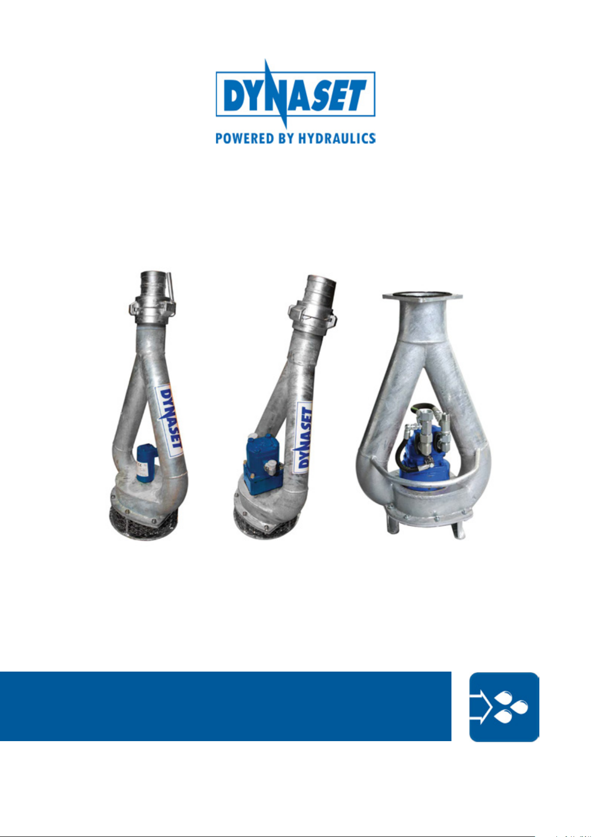
HYDRAULIC SUBMERSIBLE PUMPS
GENERAL
1. GENERAL
This manual contains general information about assembly, installation, operation
and maintenance of the DYNASET HSP hydraulic submersible pumps.
ATTENTION!
Read this user manual before installation, use or maintenance of the HSP
pump to ensure proper handling, operation and maintenance right from
the beginning. Pay attention to warnings and safety instructions. READ
CHAPTER ”2. SAFETY” for more information. for more information.
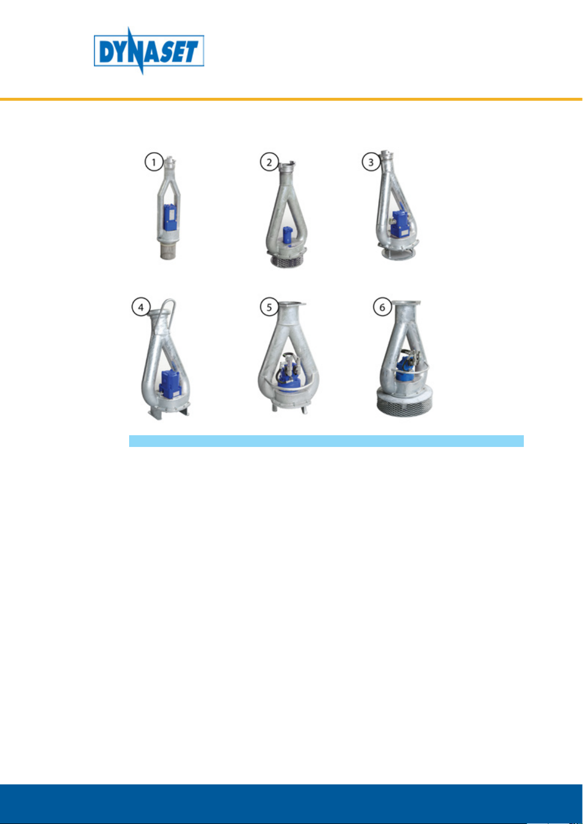
1.1. PRODUCT INFORMATION
Dynaset HSP hydraulic submersible pumps are designed for fast and efficient
pumping of water and other liquids. The volute and impeller of the HSP pump
are made of wear-resistant material which makes it a perfect choice for pumping
liquids containing impurities and solids
DYNASET submersible pumps can be used in municipal services, civil engineering,
industry, agriculture, off shore etc.