Dynaset Oy | Menotie 3, 33470 Ylöjärvi | puh. 03 3488 200 | info@dynaset.com | www.dynaset.com
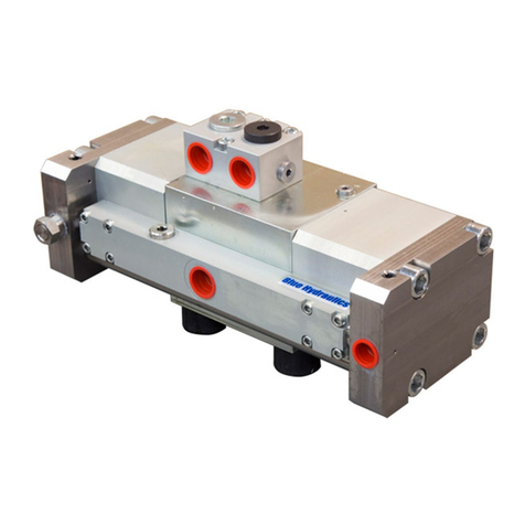
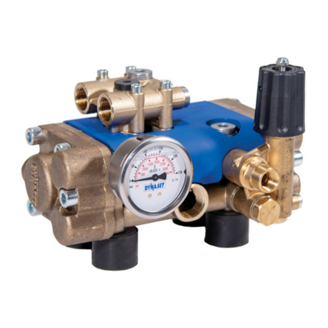
HYDRAULIC VIBRAS
TABLE OF PICTURES
Picture 1: Identication key for HVB 10
Picture 2: Identication key for HVD 10
Picture 3: HVB Type plate 11
Picture 4: HVD Type plate 11
Picture 5: HVB and HVD line-up 12
Picture 6: Main components of HVB 12
Picture 7: Main components of HVD 13
Picture 8: Operating description of HVB 19
Picture 9: Operating description of HVD 20
Picture 10: HVB installation 21
Picture 11: Installation of HVB to existing tool line 22
Picture 12: Installation of HVB with DYNASET PV-SAE priority valve 23
Picture 13: Installation of HVB with DYNASET LSV valve and switch 24
Picture 14: Installation position 25
Picture 15: Installing HVD and installation plate 25
Picture 16: Installation of HVD to existing tool line 26
Picture 17: Installation of HVD with DYNASET PV-SAE priority valve 27
Picture 18: Installation of HVD with DYNASET LSV valve and switch 28
Picture 19: Electric schema for solenoid valve 29
Picture 20: Operating HVB and HVD units 31
Picture 21: Removing the pump head 34
Picture 22: Removing the pump head and intake valve 34
Picture 23: Positioning the body 35
Picture 24: Removing the piston 35
Picture 25: Removing the piston from the cylider 35
Picture 26: Removing seals from piston and the cylinder 36
Picture 27: Installing the seals to piston and the cylinder 36
Picture 28: Lubricating the piston and the cylinder 36
Picture 29: Installing the piston assembly to the pump body 1 37
Picture 30: Installing the piston assembly to the pump body 2 37
Picture 31: Removing the pump head seals 38
Picture 32: Installing the pump heads 38
Picture 33: Removing the pump head 39
Picture 34: Removing the body seals and the piston 39
Picture 35: Removing piston shell 40
Picture 36: Replacing and lubricating piston assembly seals 40
Picture 37: Installing piston 40
Picture 38: Replacing and lubricating head seals 41
Picture 39: Installing body seals and head 41
Picture 40: Tightening the screws 42


