Dynasplint Type II User manual

CLINICIAN INSTRUCTIONS
Dynasplint® Wrist Extension System
Type II
INDICATION:
Dynasplint® Wrist Extension Systems are used for
the treatment of joint stiness and limited range of
motion due to:
Burns
CP
CVA
Dislocations
Fractures, e.g., Colles, distal radius, etc.
Head trauma
Hemophilia
MS
Rheumatoid arthritis
Spinal cord injuries
Tendon and ligament repairs
DYNASPLINT® and Dynasplint® Systems are registered trademarks of Dynasplint Systems, Inc.
Stretch Beyond Your Expectations.
®
Corporate Headquarters:
800.638.6771 toll-free
800.380.3784 fax
Canada:
800.668.9139 toll-free
905.851.3494 fax
Europe:
00131.455 230 418 phone
00131.455 231 303 fax
www.dynasplint.com

FITTING INSTRUCTIONS
IMPORTANT: Movement and rattling of spacer in the tension window is normal. This
will subside when more tension is applied to the tension screw.
STANDARD FITTING INSTRUCTIONS:
STEP 1: Completely open top-of-forearm cu and strap. Loosen the bottom-of-
forearm cu.
FIGURE 1.
STEP 2: The contour foam pad attached to the strut by a clip should be placed on
the thumb side of the hand. If necessary, remove clip with attached pad and
reverse its position with the at pad.
STEP 3: If necessary, take the unit o and adjust the length of the struts so that the
cu is located on the bulk of the muscle mass on the lower arm.
STEP 4: To shorten or lengthen the struts, rst remove the 1/8” screw near cam. Slide
the smaller tube in or out of the larger tube to obtain correct length. Replace
and gently tighten the screws. See Figure 2.
STEP 5: To lengthen strut distal to cam, loosen side set screw and adjust length.
Tighten screw gently. See Figure 3-A.
STEP 6: Without tension on the unit, place the patient’s lower arm and wrist in the
unit. Align the struts with the midlines and sides of the lower arm. Align
cams across joint axis. Fasten top-of-forearm cu loosely, leaving strap open.
Check placement. See Figure 2.
FIGURE 2.
1
Struts
Horizontal Bar
Cam
Velcro® Strap
Top-of-Forearm Cu
OPTION A HAND PIECE*
OPTION B HAND PAN
Horizontal Bar
Set Screws
Forearm Cu
Cam
Counterforce
Strap
Palmar Piece
Strut
*Hand piece is custom molded
to t patient’s hand.
Counterforce
Strap
D-wire

STEP 7: Position patient to view splint as in Figure 2. Close bottom-of-forearm cu
to position palmar bar and allow adequate wrist clearance, loosen the set
screws with adjustment tool. See Figure 3-B.
STEP 8: Lengthen or shorten horizontal bar by expanding or retracting bar until wrist
adequately clears cam. Next, slide and align the vertical post with the palm’s
midline. Tighten set screws gently.
STEP 9: Close counterforce strap and readjust top-of-forearm cu.
STEP10: Adjust stem rod height. Loosen set screws that hold the stem. See Figure 3-C.
With patient’s ngers in a relaxed, semiexed posture, position palmar bar in
the palm of hand. Tighten screws gently.
STEP 11: Adjust rotational angle of palmar bar by loosening wrist pivot assembly to
obtain comfortable position. See Figure 3-D. Tighten screws.
STEP 12: Adjust tilt of palmar bar by using the hex wrench to loosen sagittal screw.
See Figure 3-E. Tighten screw rmly.
FIGURE 3.
STEP 13: Take unit o and set the tension to the proper setting. See Protocol.
STEP 14: Reapply unit and check the alignment with Figure 2, making sure that:
Cams are aligned across the wrist axis.
Struts are placed on the medial and lateral sides of the arm.
Cu is evenly contoured across the arm, with enough space to slide
one nger under the upper and lower edge of the cu.
Palmar bar is adjusted to conform to patient’s palm.
STEP 15: Tape or mark the bottom-of-forearm cu to prevent alteration of the tting
by the patient.
STEP 16: Make a reference line with a marker on the top-of-forearm cu and counter-
force strap so that the patient knows where to close them.
STEP 17: Have the patient practice applying and removing the unit.
Give the patient the Patient Instruction Booklet to take home with the Dynasplint®
Wrist Extension System.
•
•
•
•
2
Struts
Palmar Bar
3-A Set
Screws
3-E Sagittal
Screw
3-D Wrist Pivot
Assembly
Stem Rod
Horizontal
Bar
Vertical Post
3-C Set Screws
3-B Set
Screws

PROTOCOL
Patients should wear the unit at the lowest tolerable tension setting for the longest
time possible. Optimally, the patient will wear the Dynasplint® System for six to eight
continuous hours, usually overnight. The tension should be set to produce as much as,
but not more than, one hour of post-wear stiness beyond normal discomfort. Success
in restoring range of motion depends on patient tolerance and compliance, length of
time since onset, and cause and severity of stiness/contracture, e.g., fracture, liga-
ment repair, spinal cord injury, etc.
STANDARD PROTOCOL
Protocols vary according to individual health practitioners’ discretion.
1. Conditioning and Adaptation:
Important: Movement and rattling of spacer does not mean the unit is broken. This
will subside when more tension is applied to the tension screw.
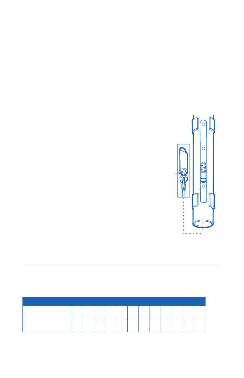
Day 1: Set tension screws at 1 on both struts. Have the patient wear the unit
for one period of up to four continuous hours. If the patient complains of pain
during the four-hour period, or reports more than one hour post-wear stiness/
discomfort, reduce tension by 0.5 increments or more if necessary on each strut,
until the patient can wear the unit four continuous hours per day.
Day 2 – Day 4: When the patient can wear the unit four continuous hours per
day, begin overnight application. With the tension still at 1 -or lower if needed-
have the patient wear the unit overnight for six to eight hours.
Advance tension setting by increments of 0.5 as tolerated to produce as much
as, but not more than, one hour post-wear discomfort/stiness beyond normal
discomfort. Higher tension settings are not always necessary to achieve results.
2. The patient should be inactive and relaxed while wearing the unit. The extremity
should be in a gravity-eliminated position. Position the patient while sitting, with
arm resting on a pillow level with the heart. In no way should the extremity be
dependent or hanging down.
3. If the patient should complain of pain, numbness, or discomfort while wearing the
unit, it should be removed; reapply the unit after reevaluation.
4. If the patient cannot adapt to overnight application, have the patient use the
Dynasplint® System during the day. In most cases, incorporating Dynasplint®
Systems early in treatment will, decrease rehabilitation time.
3

9
12
0
6
9
12
0
3
6
9
12
0
3
6
NEUROLOGICAL PROTOCOL:
Neurological patients being t in a standard unit that is neurologically dressed should
follow the NEUROLOGICAL protocol. Please see the Neurological Wrist Extension Clini-
cian Booklet for detailed instructions.
NOTE: Tension settings are dierent for the standard and neurological systems. If
patient is transferring from a NEUROLOGICAL unit to a STANDARD unit that is neuro-
logically dressed, please see the tension scale below to adjust tension properly.
TENSION ADJUSTMENT
STEP 1: Hold the unit so that you can see the tension adjustment
scales on one of the thick tubes (struts). To read tension,
press down or extend the palm pad. The etched line on
the indicator inside the strut (visible in the tension win-
dow) will line up with a number on one of the scales.
See Figure 4.
STEP 2: If the tension is not on “0” on both struts, adjust
the tension screws inside both struts, so that the
etched line on the spacers lines up with“0”. See
Figure 4. Place the rounded screw driver inside
the hollow end of the large cylinder to engage the
tension screw.
STEP 3: Turn the screwdriver clockwise to increase the
tension and counterclockwise to decrease the tension.
The indicator inside the scale will move accordingly
as tension increases or decreases, aligning with the
numbers 0-12 on the tension scale.
VERY IMPORTANT: Do this equally on both sides to balance the torque.
SPECIFICATIONS
Weight: Adult: 18.4 oz / Pediatric: 10.9 oz
Range: 0° to 90° of extension
4
Torque values expressed in foot pounds.
Standard
Wrist Extension
Measured at 30º flexion
SCALE SETTING
1 2 3 4 5 6 7 8 9 10 11 12
0.0 0.1 0.3 0.7 0.8 1.0 1.2 1.5 1.6 2.1 N/A N/A
FIGURE 4.
Tension
Screw
Torque values expressed in foot pounds.

TROUBLESHOOTING
Instruct patient to remove the Dynasplint® System immediately if pain or numbness occurs.
A hand pan can be substituted for the palmar bar and is available through the
Dynasplint® Systems representative. See options in Figure 2.
PROBLEM: Metal joints are pressing into the wrist.
SOLUTION: Open or lengthen horizontal bar.
PROBLEM: Comfort pads or Velcro® irritating the skin.
SOLUTION: Use stockinette between arm and splint.
PROBLEM: Pain.
SOLUTION: Decrease the tension by increments of 0.5 until the unit is
tolerated. Unless absolutely necessary, do not decrease
wearing time. Some patients may have to resort to day
time/evening use and/or multiple sessions, i.e., two, four-
hour daytime/evening sessions.
PROBLEM: Numbness.
SOLUTION: Check cu and straps for over-tightness. Decrease wearing
tension by increments of 0.5. Repeat adaptation wearing
schedule.
CONTRAINDICATIONS: Although Dynasplint® Systems can provide unusually con-
servative stretching force, these devices are contraindicated where range of motion
therapy is inappropriate.
PRECAUTIONS: Carpal tunnel syndrome, osteoporosis, thrombophlebitis, spasticity,
edema, gross ligament instability, and circulatory impairment.
NOTE: This device is restricted to use on the order of a licensed health care practitioner.
5


©1996 Dynasplint Systems, Inc.
Dynasplint Systems, Inc. products are covered by one or more of the following U.S.A. patents: 5,558,624; 5,645,521; 6,413,231; 6,506,172;
6,740,051; 6,908,475; 6,942,629; 6,942,631; 4,485,808; 4,508,111; 4,538,600; 4,944,290; 4,947,835; and 5,070,868. Other patents issued and/or
pending in the U.S.A. and internationally.
The product described in the enclosed literature is intended for the specic purpose as per the instructions attached. Any use of this product
outside of its intended purpose on any body part or in a manner outside the protocol established by Dynasplint Systems, Inc., is a use of the
product for which it, its divisions and employees cannot be held responsible. All implied warranties of tness for use for any other purpose (or
purposes) are expressly disclaimed.
Table of contents
Popular Medical Equipment manuals by other brands

ARJO HUNTLEIGH
ARJO HUNTLEIGH alpha active 4 Quick reference guide

SOMNOmedics
SOMNOmedics SOMNOscreen HD instruction manual

Breas Medical
Breas Medical NIPPY JUNIOR + instruction manual

Medivance
Medivance BD Arctic Sun 6000 Operator's manual

Emfit
Emfit QS IP-9360 quick guide

mychway
mychway YH-6551 user manual