DYNETICS INCORPORATED GroundAware User manual

DYNETICS INCORPORATED
GroundAware™Reconfigurable Surveillance Sensor
Installation, Operation,
and User’s Manual

G R O U N D A W A R E ™ R E C O N F I G U R A B L E S U R V E I L L A N C E S E N S O R
Installation, Operation, and User’s Manual
Dynetics, Inc.
1002 Explorer Blvd
Huntsville, AL 35806
Phone 256.964.4000

Version/
Revision
Document
Change #
Release
Date
Originator
Reason for Change
1/16/15
Joel Simoneau
and Mike Stokes
Initial version of the Installation, Operation,
and User’s Manual for the GroundAware RSS

Table of Contents
Important Safety Instructions.....................................................1
Safe Usage.....................................................................................1
General Description and Specifications ....................................2
........................................................................................................3
Specifications..................................................................................3
Installation.................................................................................4
Operation...................................................................................8
Configuration...................................................................................8
User Access....................................................................................8
User’s Guide..............................................................................8

G R O U N D A W A R E
1
Important Safety
Instructions
ARNING! Do no remove any part of the product
enclosure or create an opening in the produce enclosure in
any way. Risk of fatal electrical shock exists with any
exposure to the internal product components. Further, any
opening of modification of the enclosure by any non-Dynetics
personnel voids the product warranty and can only be reinstated by
Dynetics in writing.
The GroundAware™ product should only be used with the power and data cables
supplied with the unit by Dynetics. Failure to use provided cabling may result in
damage to the unit and increased risk of electrical shock.
Safe Usage
Dynetics recommends that at least two people be used to move the unit. The unit
should only be mounted by qualified personnel using the appropriate safety lanyards to
prevent unrestrained unit fall should the mounting fail. The mounting fixture, power
receptacle, and data receptacle used with the unit should be appropriately grounded by
a qualified electrician.
VERY IMPORTANT: GROUNDAWARE IS A
RADIATING DEVICE WITH RF HAZARDS.
INSTALLATION AND OPERATIONAL PROCEDURES
MUST ENSURE THAT NO HUMANS OR ANIMALS
PASS WITHIN ONE METER (1 m) OF THE FRONT OF
THE UNIT WHILE IT IS POWERED.
Section
1
W

2
General Description and Specifications
roundAware™ is a user Reconfigurable Surveillance Sensor that detects,
tracks, classifies, and provides actionable information relevant to objects
within a 120° field of view up to five kilometers from the sensor. This
capability is implemented via the interoperation of four sub-systems:
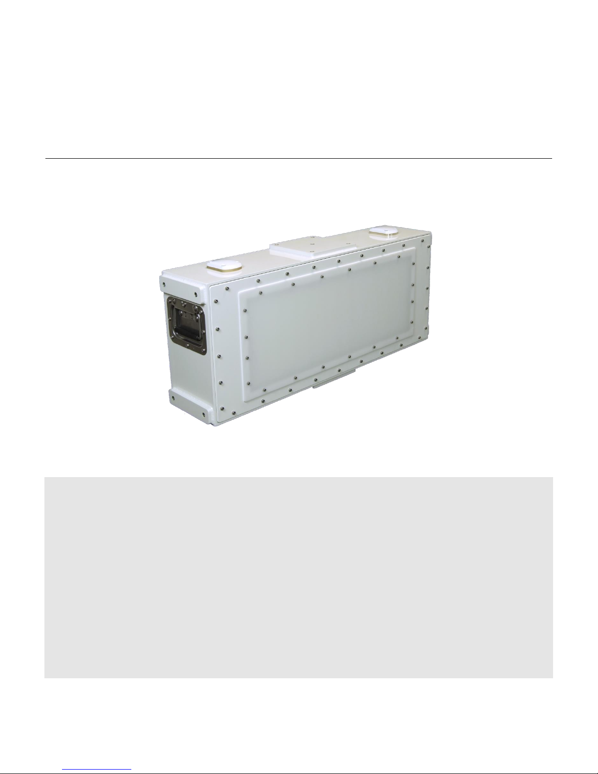
The radar sub-system transmits S-band radio frequency signals, digitizes and processes
the received returns, identifies detections, clusters detections to identify tracks, and
associates tracks with feature data that can be used to classify the object. The radar can
be configured to use three different waveforms, based on installed site, that will be
explained in further detail in later sections. This manual should be used with radar sub-
system model number 001-10018266.
The server sub-system receives track data, receives and processes classification data,
hosts the GoogleMaps based user interface, and implements external sensor (e.g.
single/dual band PTZ camera, unattended ground sensor, etc) integration. Server
hosting of the user interface includes managing user-defined alert zones, per-zone
alerting criteria, and the per-zone violation log. Commodity grade desktop or laptop
computers may be used to execute the server sub-system software.
The client sub-system renders the GoogleMaps user interface for each unique browser
session. Users may maintain their own zoom and view settings, while sharing zone
definitions, alert criteria, and camera control with other users. The user interface is
browser agnostic, but works best with Mozilla Firefox. While the client software is
executed on each user’s machine within a web browser, it is provided upon
authentication and managed by the server sub-system software.
The optional interface sub-system provides a cellular data link, optional use network
interfaces, and independent radar power on/off control. The interface sub-system also
includes the cabling, encoder, and power supplies required to integrate external
cameras or other sensors. This sub-system is self-contained in an environmentally
sealed enclosure with the external switches and connectors as required by the
customer.
GroundAware™ enables a customer to use the system in an environment where the
interface is continually monitored by personnel on desktop or mobile devices, or in an
Section
2
G

3
unmonitored environment where personnel can be alerted to intrusions based on user
defined criteria.
Figure 2-1 below illustrates how the GroundAware™ system and sub-systems interact
and what is typically provided by Dynetics and by the user/reseller. NOTE: Optional
integrated cameras and other sensors not shown.
FIGURE 2-1 GroundAware™ System/Sub-System Block Diagram
Specifications
The GroundAware™ system is a sophisticated, multi-channel digital beam-forming
device that utilizes state of the art Direct Digital Synthesis (DDS) waveform generation
and digital signal processing to detect and very accurately track small, slow targets while
minimizing false alarms. The GroundAware™ design has been refined by Dynetics
and end user testing across the United States at various critical infrastructure facilities,
and each unit is integration tested before delivery and verified to meet the

4
specifications enumerated in Table 2-2 below. NOTE: These specifications only apply
to the Radar Sub-System.
Operational Frequency
S Band: Dynetics Configurable by Site
Between 3,156.250 MHz –3,296.875 MHz
Antenna
Microstrip patch array
Azimuth Coverage
120° (60° Either Side of Radar Boresight)
Elevation Coverage
30° (15° Above/Below Radar Boresight)
Average Transmit ERP
20 W
Range Accuracy
2 m
Range Resolution
10 m
Minimum Detectable Velocity
0.5 m/sec
Instrumented Range
100 m to 5.0 km
Walker Detection Range
>2 km
Dimensions
12” x 30” x 10”
Weight
45 lbs
Power Requirements
400W max., 120Vac, 60 Hz, single phase
Data Interface
RJ45 Terminated IP4/IP6 Ethernet
Operating Ambient Temp
-20 deg C to +65 deg C
Storage Ambient Temp
-40 deg C to +80 deg C
Operating/Storage Humidity
0% at 78 °F to 100% percent at 95 °F
Operating Altitude
0 to 12,500 ft MSL
Rain Resistance
12 in./hr
Hail Resistance
3 cm hailstone strike at 30 m/s
Ice Resistance
Clear ice at 1/4 in. radial measured from the
sensor surface to the outer shell of the ice
Solar Radiation Exposure
Annual solar radiation up to 6500 MJ/m2
Sand/Dust Resistance
Dust environments of 1.03 gm/m3 Sand:
1.06 gm/m3, 40 kts wind.
Maximum Sustained Winds &
Gusts
50 mph, sustained;75 mph gusts
Browser Compatibility
Mozilla/Chrome w/ Quicktime
User Defined Parameters
User-defined alarm and ignore zones
User-defined alarm criteria per zone
TABLE 2-2 GroundAware™ System/Sub-System Block Diagram
Installation
The GroundAware™ system is very easy to install and prepare for configuration and
operation. As illustrated briefly in previous sections, installation falls into three
fundamental phases: mechanical, electrical, and data.
Mechanical installation of the system includes mounting the unit such that it is
horizontally level and perpendicular to the center point of the area to be monitored.
The unit includes carrying handles on each side to aide in the recommended two-

5
person emplacement of the system. ??? pattern X-Y-Z helicoils are included on the top
and bottom of each unit to allow a custom mount to be designed and built for
whatever fixture the customer requires.
Electrical installation includes connecting the unit to a maximum 400 watt, 120 volt, 60
Hz, single phase, grounded alternating current source using the provided power cable.
Optionally, the unit may be powered through the switch in the interface sub-system as
described previously. Any additional switches utilized in the provision of power to the
system (e.g. installed by the customer) should be rated for the type and quality of
power specified.
Data connectivity installation includes connecting the unit to an IP4/IP6 network
through which connectivity to the server sub-system can be obtained. The unit may be
connected to the server sub-system network by several different means such as, wired
50directly, cellular, Wi-Fi extending antennas, etc. based on user requirements.
Figure 2-3 below depicts the mechanical, electrical, and data interconnections of the
GroundAware™ system.

6
FIGURE 2-3 GroundAware™ Mechanical and Electrical Interconnections
Given a basic understanding of system connectivity, installation and startup should
proceed as follows, given a basic three sub-system setup:
1. Mount the radar sub-system unit mechanically per the customer site
requirements and preparations.

7
2. Connect the radar sub-system unit to the IP4/IP6 server sub-system network
using means required by the customer site.
3. Connect and power-on the server sub-system on the same IP4/IP6 network as
the radar sub-system.
4. Connect the radar sub-system to commercial power that meets the previously
provided specifications.
5. Wait approximately 90 seconds before proceeding to the activities described in
Section 3.

8
Operation
his section assumes that the precautions and setup steps of the previous two
sections have been read, understood, and followed. If any of the material or
steps from sections 1 and 2 have been skipped or poorly understood, please
pause and review the information and re-perform whatever steps may be
necessary to ensure that GroundAware™ is properly and safely installed, powered, and
connected before the activities of this section are performed.
Configuration
GroundAware™ may be generally configured by the user for three modes of
operation: short, medium, and long rage. Table 3-1 below specifies the parameters of
interest for each one of these modes.
Once the desired operational mode has been determined from the information
provided in Table 3-1, the following steps should be performed:
1. From the server sub-system, connect to the radar configuration page.
2. Select and save the configuration file corresponding to the radar sub-system
mode to be used.
3. Command the radar sub-system to begin radiating.
Note: GroundAware™ has been UL certified for operation in the three modes
described above and each unit is tested by Dynetics in each of these modes prior to
delivery. Additionally, each unit will be calibrated on-site by Dynetics personnel to
detect and track a 2m tall, 92kg human at a distance of 1610m assuming at least a 10m
emplacement height and unobstructed line of sight to target.
User Access
At this point, the desired operational mode should be set, the radar should be radiating,
and any site specific calibration by Dynetics personnel should be complete.
User’s Guide
The GroundAware™ user interface is an extended instance of GoogleMaps and is very
intuitive to use by anyone who has experience with web-based mapping web sites. The
traditional controls for zoom, pan, etc. work the same as with a standard GoogleMaps
Section
3
T

9
website. Dynetics will provide training as necessary to allow operators to monitor the
system using this interface and configure alarm zones to their preferences.
Table of contents