manuals.online logo
Brands
  1. Home
  2. •
  3. Brands
  4. •
  5. Dynex
  6. •
  7. Camera Accessories
  8. •
  9. Dynex DX-TRP61BL User manual

Dynex DX-TRP61BL User manual

V1 ENGLISH 14-0370
Storing your tripod
1Remove your camera.
2Loosen the center column set screw. Lower the column as far as
it will go, then tighten the set screw.
3Collapse the legs.
4Pull out the angle adjusting tabs and push the legs in.
5Store the tripod in the carrying case.
Important safety instructions
• Make sure that all leg locks are correctly tightened and that the
legs are fully opened before use.
• Do not carry or transport your tripod with camera equipment
attached (for example, over your shoulder or cradled in your
arms).
• Do not expose your tripod to excessive heat or cold, or use near
any ame or re.
• Do not oil or grease any part of the tripod.
• Do not use any solvents or thinners to clean your tripod. Use
only a mild detergent and wipe dry with a soft, lint-free cloth
only.
• Do not exceed the load limit of this tripod.
Specications
• Maximum operating height: 61 in. (157.5 cm)
• Minimum operating height: 17.3 in. (44 cm)
• Folded height: 22.4 in. (57 cm)
• Net weight: 3.0 lbs (1.4 kg)
• Max operating load: 6.6 lbs (3 kg)
• Number of leg sections: 4
• Quick release thread: 1/4 in. (0.6 cm)
• Panoramic angle: horizontal: 360° and vertical: 90°
• Material: aluminum alloy
One-year limited warranty
Visit www.dynexproducts.com for details.
Contact Dynex:
For customer service, call 800-305-2204 (U.S. and Canada) or
01-800-926-3020 (Mexico)
www.dynexproducts.com
DYNEX is a registered trademark of BBY Solutions, Inc.
Registered in some countries.
Distributed by Best Buy Purchasing, LLC, 7601 Penn Ave South, Richeld, MN 55423 U.S.A.
©2014 BBY Solutions, Inc. All Rights Reserved.
QUICK SETUP GUIDE
DX-TRP61BL
61" Eco-Pro Tripod
Before using your new product, please read
these instructions to prevent any damage.
Angle
adjusting tab
Leg
Package contents
• Tripod
• Carrying case
• Quick Setup Guide
Features
• Universal head ball
• Two-angle leg setting
• Quick ip leg locking
system
• Retractable hook
• Steady and easy operation
Setting up your tripod
1Open the ip-lever leg locks on each leg. Open the leg sections
from the top down (thickest section rst) to the height you want.
Note: Adjusting the thickest leg sections rst gives your tripod more
stability and support.
2Close the ip-lever leg locks to lock each leg.
Caution: Securing a leg lock incorrectly can cause a leg to retract
unexpectedly and could result in damage to the tripod or equipment
mounted on the tripod.
3Set the angle position by pulling out the angle adjusting tab and
lifting the tripod leg, then press the angle adjusting tab to lock
the leg.
4Adjust the height of the center column by loosening the center
column set screw, raising the center column to the height you
want, then tightening the set screw.
5Loosen the quick-release plate locking knob, press the safety lock
pin, then lift the mounting plate to remove it.
6Align the bottom of your camera or camcorder with the
1/4" mounting screw, then secure your camera or camcorder to
the plate with the screw. The screw should be tight.
7Press the safety lock pin, then slide the plate onto the tripod
head. Turn the quick-release plate locking knob until it stops to
secure the plate.
Using your tripod
1To adjust the ball head, turn the ball head locking knob
counter-clockwise, adjust the ball head, then lock the ball head
in place by turning the knob clockwise until tight.
2To adjust the horizontal movement of the head, turn the
horizontal pan locking knob counter-clockwise, move the ball
head into the position you want, then lock the head in place by
turning the knob clockwise until tight.
3For low angle shooting, unscrew the retractable
hook, then remove the center column. Reverse
the direction of the center column, then insert
the column into the base. Screw the
retractable hook into place.
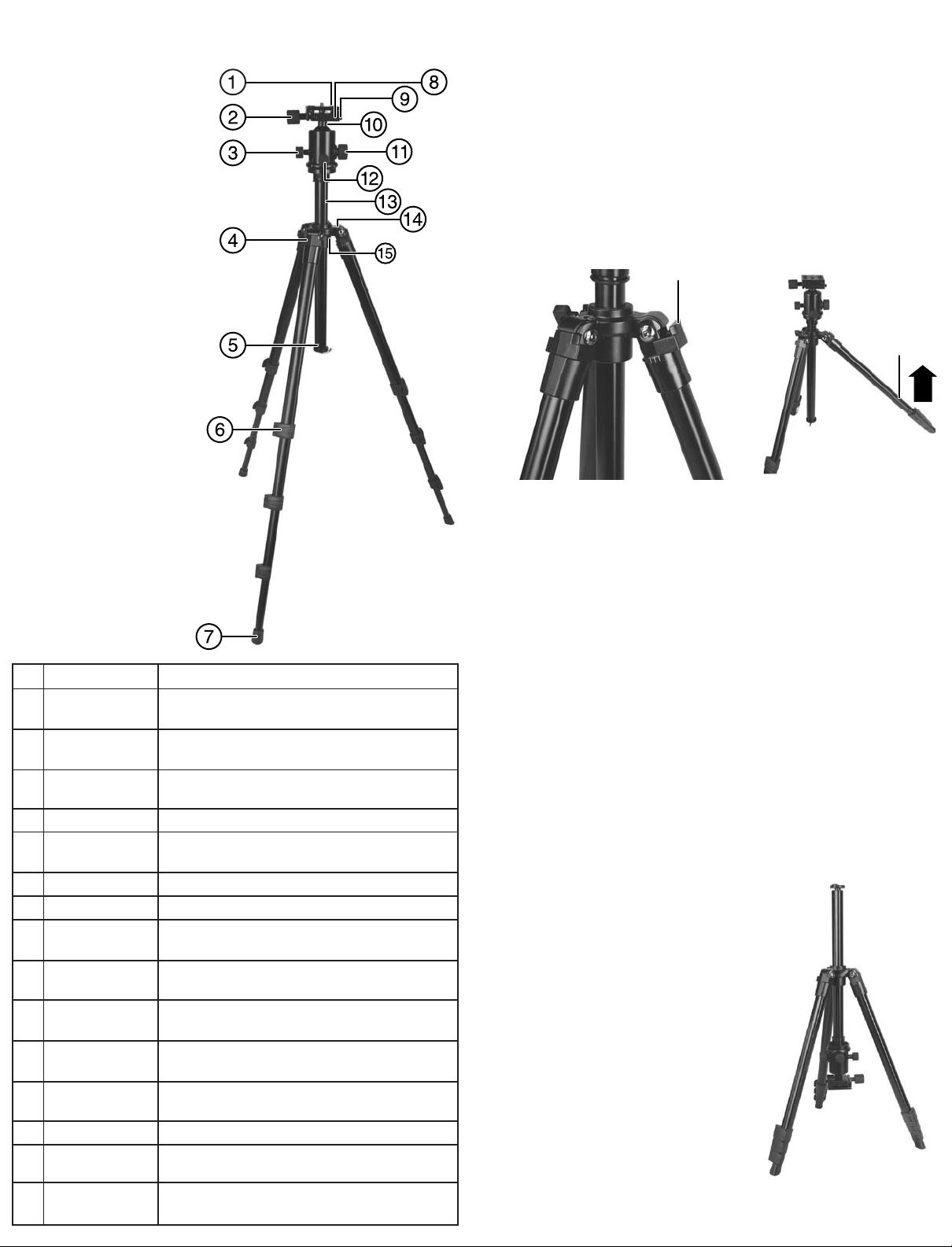
# Item
1 Quick-release
mounting plate
2 Quick-release plate
locking knob
3 Micro-adjustment
knob
4 Angle adjusting tab
5 Retractable hook
6 Flip-lever leg locks
7 Rubber foot
8 Mounting base
plate
9 Safety lock pin
10 Variable angle ball
head
11 Ball head locking
knob
12 Horizontal pan
locking knob
13 Center column
14 Leveling bubble
15 Center column set
screw
Description
Mount your device to this removable plate.
Locks the quick-release mounting base plate to the
tripod.
Adjusts the movement of ball head slightly.
Lets you adjust the leg angle position.
Hang a heavy item on this hook to add stability to the
tripod.
Lift to adjust leg height, then close to lock.
Provides a secure, non-slip footing for your tripod.
Slide the quick-release mounting plate into this base
plate.
Prevents the mounting plate from falling out when the
quick-release plate locking knob is released.
Allows the ball head to be adjusted to any angle.
Loosen to set the ball head at a dierent angle.
Loosen to adjust the horizontal pan movement. Tighten
to lock the horizontal movement of the ball head.
Adjustable column provides a quick height adjustment.
The tripod base is level when the bubble is within the
circle.
Adjusts and secures the height of the center column.
(The locking set screw is
not shown. It is located on
the opposite side not
shown in this image.)

Other Dynex Camera Accessories manuals

Dynex DX-TRP60 Owner's manual

Dynex

Dynex DX-TRP60 Owner's manual

Dynex DX-TRP58BL User manual

Dynex

Dynex DX-TRP58BL User manual

Dynex DX-TRPFLX Installation and operation manual

Dynex

Dynex DX-TRPFLX Installation and operation manual

Dynex DX-SFLX6B User manual

Dynex

Dynex DX-SFLX6B User manual

Dynex DX-TRP60 User manual

Dynex

Dynex DX-TRP60 User manual

Dynex DX-DGPK03 User manual

Dynex

Dynex DX-DGPK03 User manual

Dynex DX-SW040 User manual

Dynex

Dynex DX-SW040 User manual

Dynex DX-DA101381 User manual

Dynex

Dynex DX-DA101381 User manual

Dynex DX-MW010 User manual

Dynex

Dynex DX-MW010 User manual

Dynex DX-TRPMN665 User manual

Dynex

Dynex DX-TRPMN665 User manual

Dynex DX-NW080 User manual

Dynex

Dynex DX-NW080 User manual

Dynex DX-TRPFLX Installation and operation manual

Dynex

Dynex DX-TRPFLX Installation and operation manual

Dynex DX-MNP70BL User manual

Dynex

Dynex DX-MNP70BL User manual

Dynex DX-TRPFLX User manual

Dynex

Dynex DX-TRPFLX User manual

Dynex DX-TRPMN57 User manual

Dynex

Dynex DX-TRPMN57 User manual

Popular Camera Accessories manuals by other brands

Videotec MNVCAVTPSC 0604 operating instructions

Videotec

Videotec MNVCAVTPSC 0604 operating instructions

RIDGID R9937B Operator's manual

RIDGID

RIDGID R9937B Operator's manual

Pylontech US2000B+ product manual

Pylontech

Pylontech US2000B+ product manual

PROAIM P-WV-2PL-PP instruction manual

PROAIM

PROAIM P-WV-2PL-PP instruction manual

Tiffen Steadicam Zephyr operating manual

Tiffen

Tiffen Steadicam Zephyr operating manual

EnerSys Oerlikon Evolution instructions

EnerSys

EnerSys Oerlikon Evolution instructions

Sony XCD-V50CR operating instructions

Sony

Sony XCD-V50CR operating instructions

dji OSMO MOBILE 3 user manual

dji

dji OSMO MOBILE 3 user manual

Westcott 1881 Setup instructions

Westcott

Westcott 1881 Setup instructions

USA GEAR TrueSHOT GRCMDSS200BKEW user guide

USA GEAR

USA GEAR TrueSHOT GRCMDSS200BKEW user guide

dji Ronin-S user guide

dji

dji Ronin-S user guide

Sony XDCAM PDW-U1 Operation manual

Sony

Sony XDCAM PDW-U1 Operation manual

Sony Cyber-shot DSC-S600 supplementary guide

Sony

Sony Cyber-shot DSC-S600 supplementary guide

Teradek RT quick start guide

Teradek

Teradek RT quick start guide

PROAIM Gripmag Assembly manual

PROAIM

PROAIM Gripmag Assembly manual

Zircon SuperScan M1 user manual

Zircon

Zircon SuperScan M1 user manual

Bioenno Power BLF-0612C user manual

Bioenno Power

Bioenno Power BLF-0612C user manual

DVTEC EngRig manual

DVTEC

DVTEC EngRig manual

manuals.online logo
manuals.online logoBrands
  • About & Mission
  • Contact us
  • Privacy Policy
  • Terms and Conditions

Copyright 2025 Manuals.Online. All Rights Reserved.