Dynisco 1480 User manual

From lab to production,
providing a window into the process
-1-
www.dynisco.com
Rev: n/aP/N: n/a ECO: n/a
Dynisco 1480 1/8 DIN Indicator
Concise Product Manual 59471-5
Operang Manual
From lab to production,
providing a window into the process
-2-
www.dynisco.com
Rev: n/aP/N: n/a ECO: n/a
CAUTION: Installaon should be only performed by technically competent
personnel. Local Regulaons regarding electrical installaon & safety must be
observed. The host equipment is required to provide a suitable electrical, mechanical
and re enclosure to meet relevant safety standards. Impairment of protecon will
occur if the product is used in a manner not specied by the manufacturer.
CAUTION: All power supply connecons to the device must be removed when
carrying out any form of maintenance.
1. Installaon
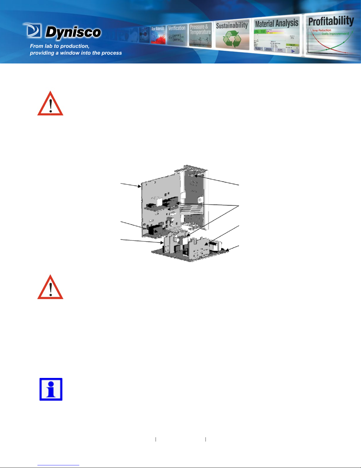
Installing Opon Modules/Maintenance
CPU PCB
Opon Module 2
Opon Module 1
Mounng Struts
Opon Module 3
PSU PCB
Future Opons
To access modules, rst detach the PSU and CPU boards from the front by liing rst the upper, and
then lower mounng struts. Gently separate the boards.
a. Plug the required opon modules into the correct connectors, as shown below.
b. Locate the module tongues in the corresponding slot on the opposite board.
c. Hold the main boards together while relocang back on the mounng struts.
Replace the instrument by aligning the CPU and PSU boards with their guides in the housing, then
slowly push the instrument back into posion.
NOTE: Opon modules are automacally detected at power up.

From lab to production,
providing a window into the process
-3-
www.dynisco.com
Rev: n/aP/N: n/a ECO: n/a
Opon Module Connectors
Panel Mounng
Not used
Not used
Opon Slot 2
Connector PL4A
Opon Slot 3
Connector PL4B
Opon Slot 1
Connectors
PL7 & PL8
The mounng panel must be rigid, and may be up to 6.0mm
(0.25inch) thick. Cut-out sizes are:
Cut-Out Dim A = 92mm
Cut-Out Dim B = 45mm
For n mulple instruments mounted side-by-side, cut-out A is 96n-4mm
Tolerance +0.5, -0.0mm
NOTE: For an eecve IP66 seal against dust and moisture, ensure gasket is well
compressed against the panel, with the 4 tongues located in the same ratchet slot.
Mounng Panel
Instrument
Housing
Ratchets
Gasket
1. Insert instrument into the
panel cut-out.
2. Hold front bezel rmly
(without pressing on display
area), and re-t mounng
clamp. Push clamp forward,
using a tool if necessary, unl
gasket is compressed
and instrument held rmly
in posion.

From lab to production,
providing a window into the process
-4-
www.dynisco.com
Rev: n/aP/N: n/a ECO: n/a
Rear Terminal Wiring
Connecons
All connecons to the device must be made through a spade format or similar
connecon, with connecon to the spade terminal touching both the insulaon and
conductor material. (Use a standard crimping tool). Connecons must be
mechanically secured so as to prevent any wiring becoming loose and coming in
contact with other wires or the instrument casing.
The above applies to any and all connecon to hazardous mains supply either
direct or indirect (Through a switch (Relay)) USE COPPER CONDUCTORS (EXCEPT
FOR T/C INPUT) Use Screened Cable on Retransmission Opon 1 Single Strand wire
gauge: Max 1.2mm (18SWG)
This diagram shows all possible opon combinaons. The actual connecons
required depend on the opons ed.
From lab to production,
providing a window into the process
-5-
www.dynisco.com
Rev: n/aP/N: n/a ECO: n/a
CAUTION: Check informaon label on housing for correct operang voltage before
connecng supply to Power Input. Fuse: 100 – 240V ac – 1amp an-surge 24/48V ac/
dc – 315mA an-surge
Electrical shock can result in death or serious injury. Avoid contact with the leads and
terminals. High voltages that may be present on leads can cause electrical shock
Note: At rst power-up the message Goto ConF is displayed, as described in secon 6 of this
manual. Access to other menus is denied unl conguraon mode is completed
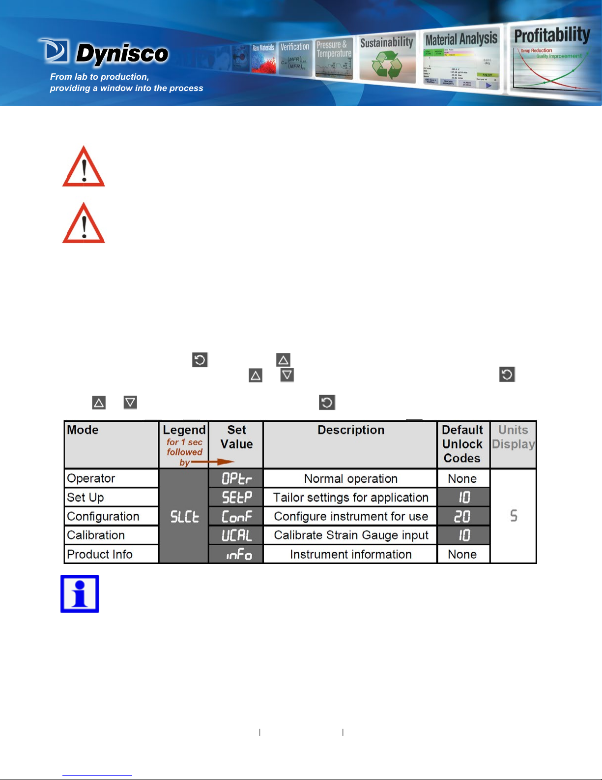
2. Select Mode
Select mode is used to access the conguraon and operaon menu funcons. It can be accessed at
any me by holding down and pressing . The SLCt legend is shown for 1 second, followed by
the legend for the current mode. Press or to choose the required mode, then press to
enter. An unlock code is required to prevent unauthorised entry to Conguraon, & Setup modes.
Press or to enter the unlock code, then press to proceed.
NOTE: Automac return to Operator Mode aer 2 minutes without key acvity.
From lab to production,
providing a window into the process
-6-
www.dynisco.com
Rev: n/aP/N: n/a ECO: n/a
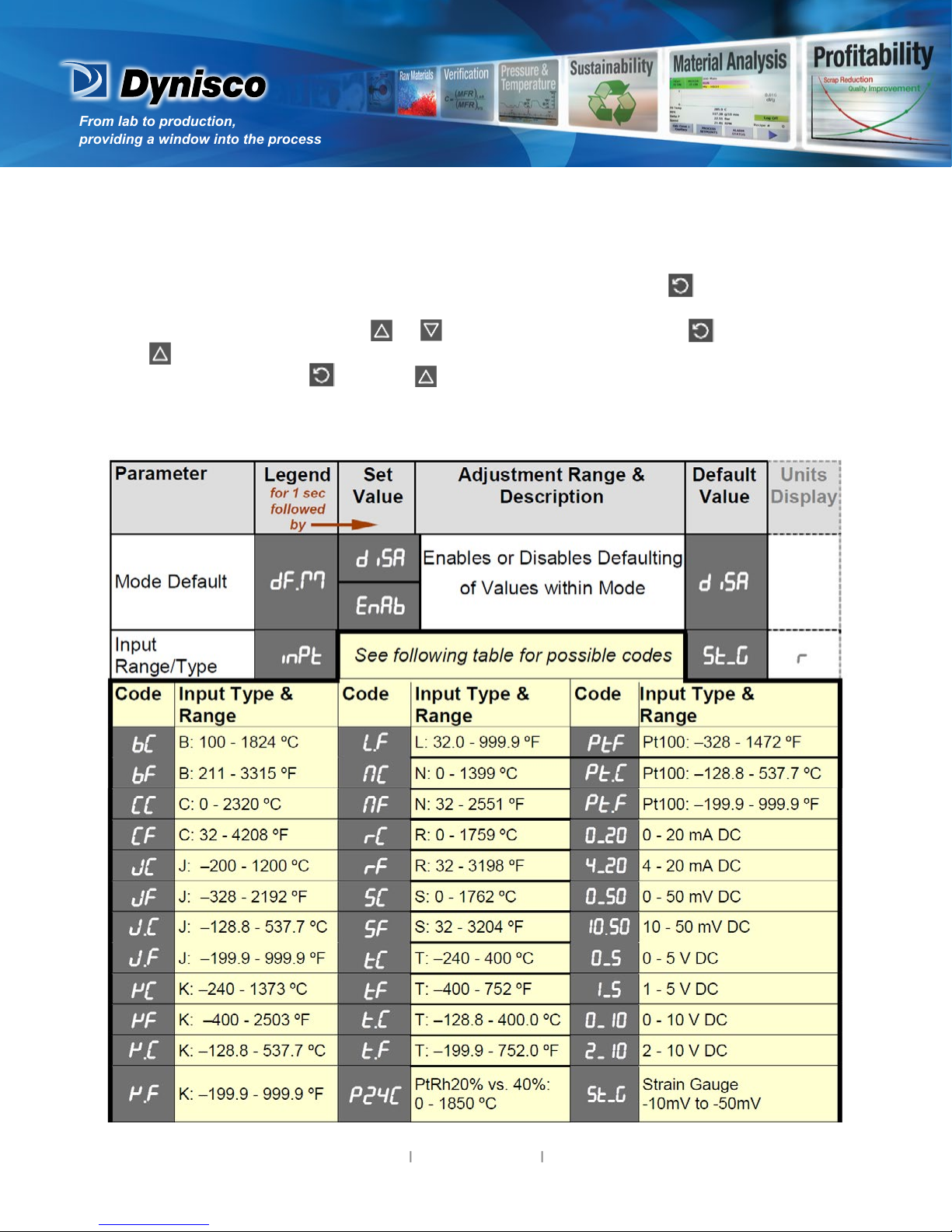
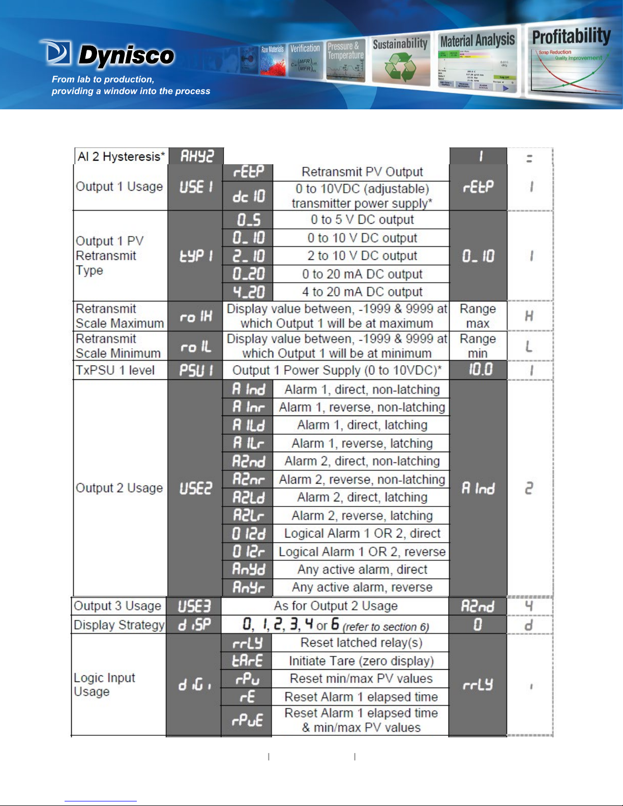
3. Conguraon Mode
First select Conguraon mode from Select mode (refer to secon 2). Press to scroll through
the parameters. While this key is pressed, and up to 1 second aer, the parameter legend is shown,
followed by the current value. Press or to set the required value. Press to display YES?
,press accept the change, otherwise parameter will revert to previous value. To exit from Con-
guraon mode, hold down and press , to return to Select mode. Note: Parameters
displayed depends on how instrument has been congured. Refer to user guide (available from
your supplier) for further details. Parameters marked * are repeated in Setup Mode.

From lab to production,
providing a window into the process
-7-
www.dynisco.com
Rev: n/aP/N: n/a ECO: n/a
From lab to production,
providing a window into the process
-8-
www.dynisco.com
Rev: n/aP/N: n/a ECO: n/a

From lab to production,
providing a window into the process
-9-
www.dynisco.com
Rev: n/aP/N: n/a ECO: n/a
4. Setup Mode
Note: Conguraon must be completed before adjusng Setup parameters. First select Setup
mode from Select mode (refer to secon 2). Press to scroll through the parameters (while this
key is pressed, and for 1 sec aer, the parameter legend is shown, then the current value). Press
or to change the value. To exit from Setup mode, hold down and press to return
to Select mode. Note: Parameters displayed depends on how instrument has been congured.

From lab to production,
providing a window into the process
-10-
www.dynisco.com
Rev: n/aP/N: n/a ECO: n/a
Table of contents
Other Dynisco Touch Panel manuals


Popular Touch Panel manuals by other brands


IBASE Technology
IBASE Technology ASTUT-152-RE1S user manual

YASKAWA
YASKAWA TP 610C manual

B&R
B&R Power Panel C Series user manual

Beijer Electronics
Beijer Electronics X2 control Hardware and installation manual

AXIOMTEK
AXIOMTEK GOT321W-521 user manual

TRIDONIC.ATCO
TRIDONIC.ATCO x-touchBOX Operation manual


