Rev B, ECN 12897, 08/18/16
3
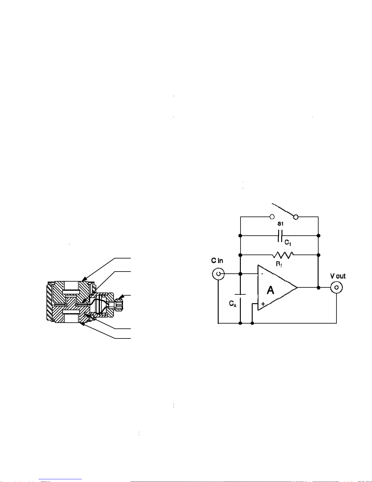
-q
Vo = -------- (Eq 1)
C
f
Where:
V
o is the output voltage (Volts)
q is the input charge, (pC)
C
fis the feedback capacitor, (pF)
This means that the sensitivity of the charge
amplifier is determined by the value of the feedback
capacitor only. Since the output voltage is fed back
to the summing junction of the amplifier (the input
terminal) the virtual input impedance is extremely
high which means that the charge signal generated
by the quartz crystals will not be drained away by
the measuring device.
SIGNAL POLARITY
Compressive forces on these sensors (see
Figure 1) produce negative-going output signals.
This is because most charge amplifiers are inverting
amplifiers and the output signal from the charge
amplifier will be positive going for compressive
loads. This is conventional.
By the same token, tension loads on the
1051C will produce positive-going output signals.
SENSITIVITY
The nominal charge sensitivity of Model
1051C is -18 pC/Lb.
CHARGE AMPLIFIER SELECTION
Dytran manufactures many different types of
charge amplifiers to suit the needs of most any
measurement requirement from the larger laboratory
type Model 4165 which features ranging and filtering
plus standardization to the miniature in-line types
4751 and 4705 which adapt the 1051C to LIVM
operation with constant current power units.
For laboratory measurements, the 4165 is
recommended and for field use, the dedicated
sensitivity n-line charge amplifiers may be a better
choice.
Consult the factory for recommendations on
the best type of charge amplifier for your
measurement needs.
INSTALLATION
Refer to outline/installation drawing 127-
1051C, supplied with this guide.
To mount model 1051C, it is necessary to
prepare a flat smooth mounting surface of 5/8”
minimum diameter. The surface should be flat to
.0005 TIR for best results.
The surrounding area must provide for room
to connect the cable to the 10-32 connector at the
end of the radial connector housing. Drill and tap a
1/4-28 hole to accept the model 6204 1/4-28
mounting stud. Thread in the mounting stud
(supplied) to secure the 1051C to its mounting
surface.
Before mounting the 1051C, thread the
sensor into the mounting port and examine the fit of
the mounting surfaces. They must meet parallel, i.e.,
a wedge must not be formed between these
surfaces. Also, at this time, inspect the mating
surfaces for foreign particles, which may become
lodged between these surfaces and clean if
necessary. It is important that the mating surfaces
meet squarely and intimately with no particles of
foreign matter of any kind included between them.
Foreign particles included between mating surfaces
could damage the sensor and/or modify the
sensitivity of the sensor.
When you are satisfied that the surfaces are
square and clean, place a thin layer of silicone
grease on one of the surfaces and thread the force
sensor place, torquing it in place with 25 to 30 Lb-
inches of torque to secure.
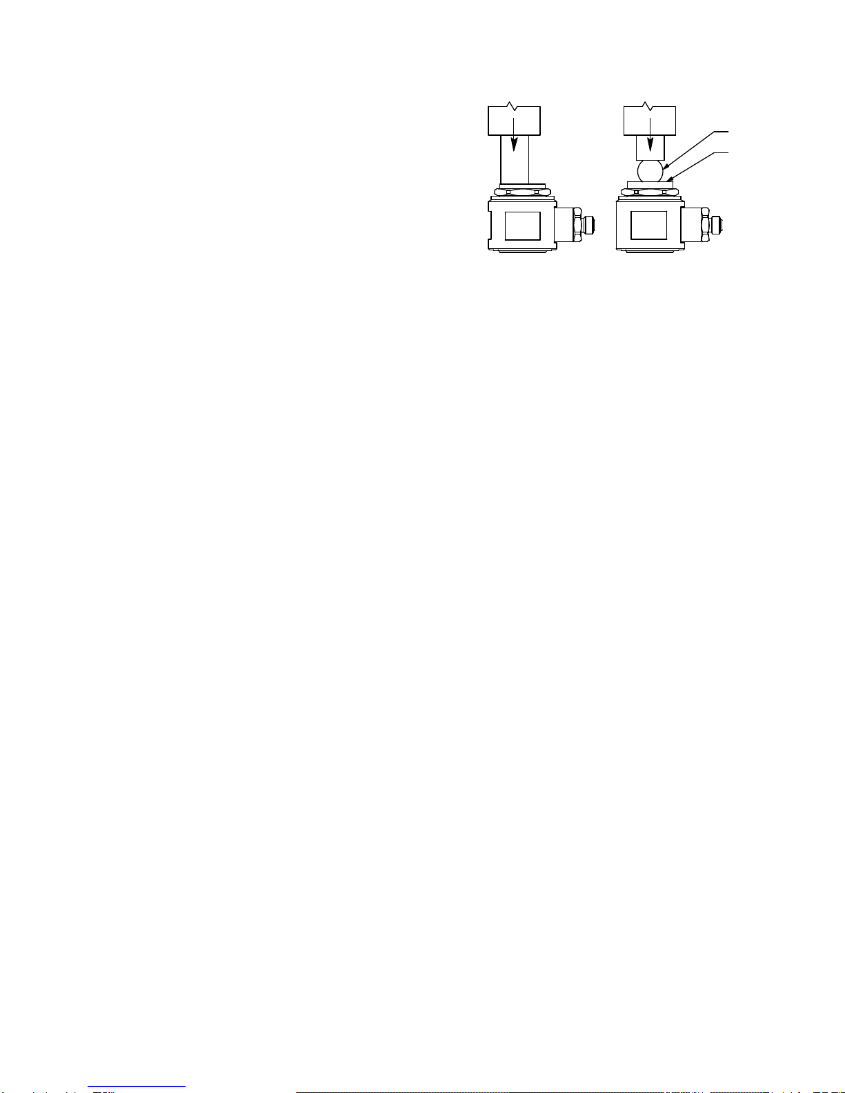
For most impact applications, the Model
6210S (steel) impact cap will be utilized. This cap is
threaded into the platen (top surface of the force
sensor). Thread this cap securely into the tapped
hole in the platen, again inspecting for foreign
particles between mating surfaces and clean if
necessary. For more permanent installations,
thread-locking compounds may be used to secure
the installation. Use these compounds sparingly.
For a slightly higher resonant frequency, the
aluminum cap, Model 6210A, may be a better choice
in some applications.
Connect the sensor to the charge amplifier
using Series 6010AXX cable (10-32 to 10-32) or
Series 6011AXX (10-32 to BNC plug), depending on
the connector called for by the power unit. Tighten