E Star ES-880 User manual
ES-880
DMX512 CV Decoder
ES-880
1
4
1. Product parameter
Input voltage
Max load current
Max output power
Output Scale level
Working temperature
Package size
Weight(G.W)
DC5V~24DC V
3A/CH×24CH Max 72A
360W/864W/1728W(5V/12V/24V)
L260×W120×H40mm
L290×W130×H46mm
Dimension
-30 -65
860g
ES-880 DMX512 CV Decoder Manual ES-880 DMX512 CV Decoder Manual
Thanks for choosing our ES-880 DMX512 decoder, ES-880 DMX512 decoder
converts the universal standard DMX512/1990 signal into PWM signal to drive
LED. It creates exclamatory, soft&perfect color fade effect by adopting special
L-PWM program technology, which makes the LED more colorful and vivid.
256 levels
DMX512/1990
24Ch
Input signal
Output DMX Channel
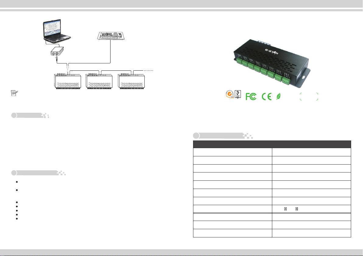
DMX console connection
NOTE: According to DMX512 protocol, in order to ensure a steady DMX Data trans
mission, you should weld a metalster(Metal Thin Film resistor,90-120Ω1/4W)at the
Data -),Please also refer to your DMX console manua to select a correct resistor.
5. Attention
6. After sales service
DC+
DC-DC+DC-
DMXIN
DMXOUT
DMXIN
DMXOUT
DMXIN
DMXOUT
ES-880
DMX data input
USB-DMX
Converter
DC5-24V
DC5-24V DC5 -2 4V
DMX OU T DMX IN DMX O UT
DMX512
PC CONSOLE
DMX512 CONSOLE
DMX IN DMX OU T
ES-880 ES-880
DC+
DC-DC+DC- D C+
DC-DC+DC-
end of each Layouteach layout of DMX data cable(between Foot 2 and Foot 3, Data+l and
Power supply chosen DC CV SMPS
RoHS
COMPLIANT
warranty
3 years
ISO9001:2008
1. The product shall be debugged and installed by professional persons.
2. This product is non-waterproof, please avoid the sun and rain. Put it in a water- proof box if
install outdoor.
3. Good condition of heat dissipation will prolong the working life of controller, please install the
product in a good ventilated condition.
4. Please check if the output voltage of the LED power supply comply with the voltage range of
the product.
5. The diameter of adopted cable should load enough connected LED light. Ensure a solid
connection in order to avoid triggering accident result from poor contact or cable overheat.
6. Ensure all wire connection are correct before power debugging, which is to avoid lamps to be
burnt because of wrong connection.
7. Please do not maintain it by yourself if any fault, please contact your supplier if any question.
1. Our LED controllers are provided with lifelong technical maintenance and warranty service.
Free warranty: Within 3 years from the date of purchase, we will offer free repair or
replacement if any product quality problem.
Charge warranty: If the product beyond the free charge maintenance period, we will charge
certain material cost.
2. The below situations exclude from free warranty.
The damage caused by improper connection to power supply, exceeded voltage, overload.
Use the product in a incorrect way.
The appearance of the product has been damaged severely or be out of shape.
Natural disasters and force majeure damage.
Warranty fragile label and the unique barcode have been damage.
3. The most responsibility we take is that we change the same models and same quantities products.
4. As for the repair products, please write down the description to malfunction, working environment,
and what you have done when malfunction happened, which are helpful to solve the problems
quickly.
This manual is only apply to this model. Any update is subjected to change without prior notice.
23
2. Basic Features
3. Decoder address setting
2. Testing function:
ES-880 DMX512 CV Decoder Manual ES-880 DMX512 CV Decoder Manual
1. Special L-PWM program technology, with more functions;
2. 24 output channels, which can connect signal color or RGB full-color lamps;
3. 0-100% smooth brightness adjusting, 256 grey steps per channel;
4. Universal standard DMX512 input protocol, addresses can be set up by DIP switch;
5. Working voltage from DC12V~DC24V;
6. With 10 auto testing modes and 8 speed adjusting modes;
FUN at “OFF” is DMX512 signal mode FUN at “ON” is auto testing mode
1 2 3 4 5 6 7 8 9 10
ON
0
1
OFF
ON
Picture 1
1. DMX initial address setting
DIP Switch
FUN at “OFF” (the10th DIP switch is upward) is DMX512 signal mode, pic 1
Value
1
2
3
4
5
6
7
8
9
001
002
004
008
016
032
064
128
256
Remark
This decoder adopts Dip switch to set the address,
the Dip switches from 1 to 9 are a kind of binary
value coding switches which used for setting DMX512
initial address code, the correlative bits is the 1-9
st th
bits of the DIP switch, the 1 bit is LSC, the 9 bit
MSC , 511 addresses totally.
DMX512 initial address is the total amount of the
Dip switches' number from 1 to 9, press Dip switch
downward (ON: at position “1”), user can get the
number of its position, if pressing upward (at
position “0”), the number of its position is 0.
Example 1: Set initial address to 37
st rd th
Set the 1 , 3 , 6 , bit of the DIP switch downward to “1”the rest to “0”
(picture 2), the summation from 1 to 9 is 1+4+ 32, so the DMX512 initial address
code is 37.
12345678910
ON
0
1
OFF
ON
Picture 2
12345678910
ON
0
1
OFF
ON
th
Such as FUN at “ON” (the 10 DIP switch is downward) is testing function.
DIP switch 1-9 at “OFF” is Black
DIP1 DIP2 DIP3 DIP4 DIP5 DIP6 DIP7 DIP8 DIP9
Red Green Blue Yellow Purple Cyan White Scan Color changing
th th
DIP8/DIP9 at “ON” (the 8 /9 DIP swithc is dowanward) is changing mode.
DIP switch 1-7 has 8 levels speed changing, DIP 7 is the fastest speed.
DIP switch 1-7 at “OFF” is speed 0
DIP1 DIP2 DIP3 DIP4 DIP5 DIP6 DIP7
Speed 1
12345678910
ON
0
1
OFF
ON
Speed 2 Speed 3 Speed 4 Speed 5 Speed 6 Speed 7
As the above pic, if several DIP switch at “ON”, it is subject to the maximum value.
if all DIP switch at “ON”, it is color fade effect of testing function, the speed is 7.
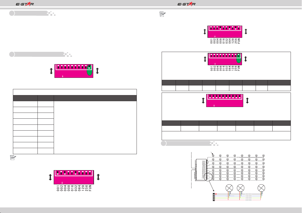
4. Conjunction Diagram
1.Connecting LED lamp:
Example 2: Set initial address to 328
th
Set the 4 , 7 , 9 , bit of the DIP switch downward to “1”the rest to “0”
th th
(as picture 3), the summation from 1 to 9 is 8+64+ 256, so the DMX512 original
address code is 328.
Picture 3
12345678910
ON
0
1
OFF
ON
R
G
B
Output Po rt
LED Light LED Lig htLED Light
LED Light
DMX IN
DMX OUT
12345678
DC+
DC-DC+DC-
DMXIN
M
DXU
OT
L -T 880
DC5V-12V


 user manual")


