Gewiss GHORUS GWA9801 User manual

KNX single-phase energy meter
with direct connection
GWA9801
Technical Manual

2
Contents
1Introduction ................................................................................................................................................ 4
2Application.................................................................................................................................................. 4
2.1 Association limits................................................................................................................... 4
3"Information” menu..................................................................................................................................... 5
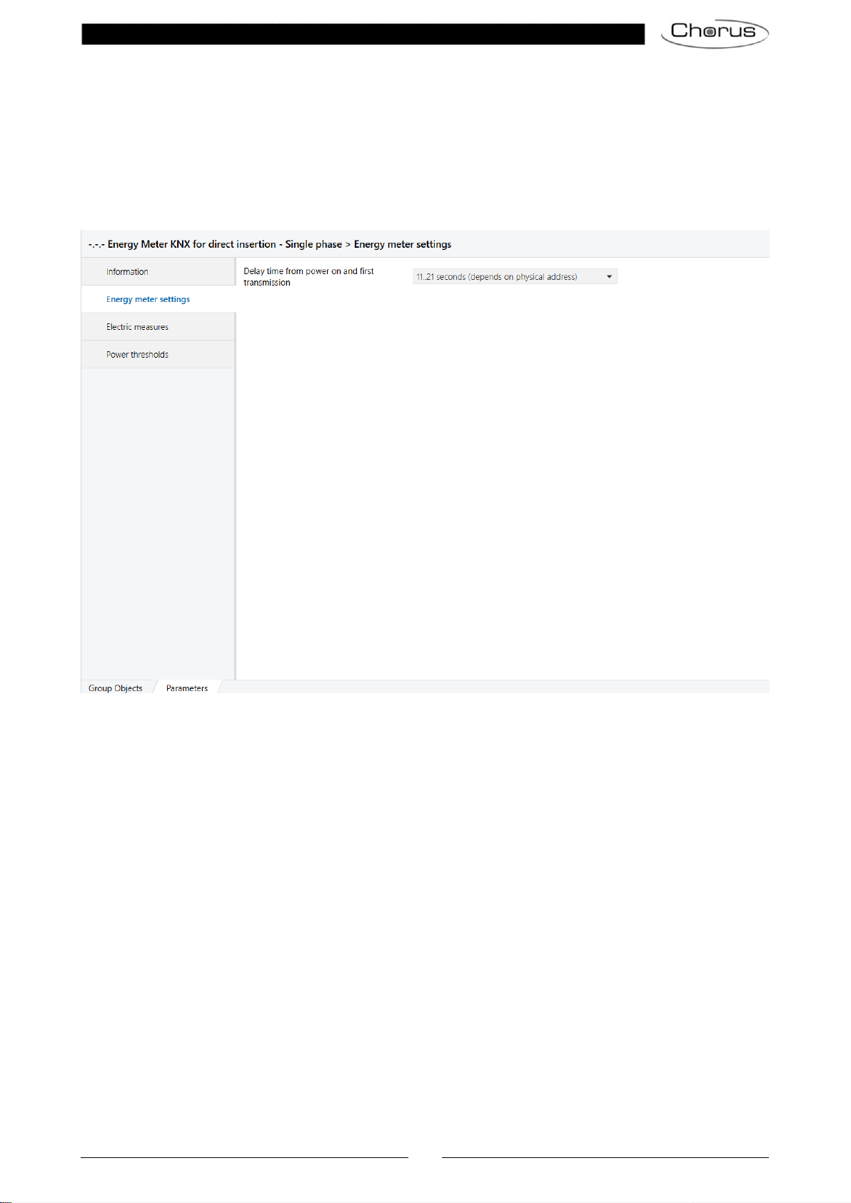
4“Energy meter settings” menu.................................................................................................................... 6
4.1 Parameters............................................................................................................................ 6
4.1.1 Delay time from power on and first transmission .................................................................. 6
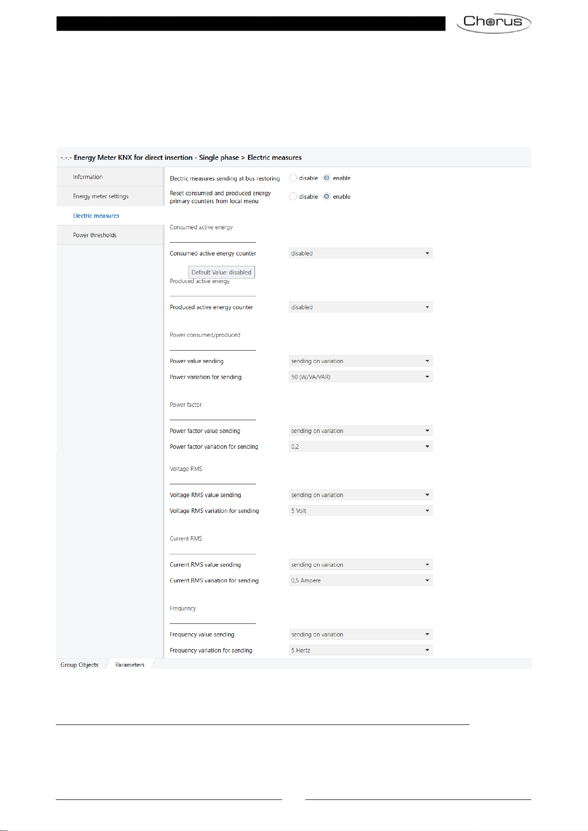
5“Electric measures” menu.......................................................................................................................... 8
5.1 Parameters............................................................................................................................ 9
5.1.1 Electric measures sending at bus restoring .......................................................................... 9
5.1.2 Reset consumed and produced energy primary counters from local menu ......................... 9
5.1.3 Consumed active energy counter.......................................................................................... 9
5.1.4 Consumed energy counter format....................................................................................... 10
5.1.5 Consumed energy primary counter init value...................................................................... 10
5.1.6 Consumed energy primary counter sending condition........................................................ 11
5.1.7 Consumed energy primary counter variation for sending ................................................... 11
5.1.8 Consumed energy primary counter sending period (minutes)............................................ 11
5.1.9 Reinitialize consumed energy counters .............................................................................. 11
5.1.10 Consumed energy differential counter overflow value ........................................................ 12
5.1.11 Consumed energy differential counter sending condition................................................... 12
5.1.12 Consumed energy differential counter variation for sending............................................... 12
5.1.13 Consumed energy differential counter sending period (minutes) ....................................... 13
5.1.14 Start/stop consumed energy differential counter from bus ................................................. 13
5.1.15 Produced active energy counter.......................................................................................... 13
5.1.16 Produced energy counter format......................................................................................... 14
5.1.17 Produced energy primary counter init value........................................................................ 14
5.1.18 Produced energy primary counter sending condition.......................................................... 14
5.1.19 Produced primary counter energy variation for sending ..................................................... 15
5.1.20 Produced energy primary counter sending period (minutes).............................................. 15
5.1.21 Reinitialize produced energy counters................................................................................ 15
5.1.22 Produced energy differential counter overflow value .......................................................... 15
5.1.23 Produced energy differential counter sending condition..................................................... 16
5.1.24 Produced energy differential counter variation for sending................................................. 16
5.1.25 Produced energy differential counter sending period (minutes) ......................................... 16
5.1.26 Start/stop produced energy differential counter from bus................................................... 17
5.1.27 Transmission of the power values....................................................................................... 17
5.1.28 Power variation for sending................................................................................................. 17
5.1.29 Transmission of the power values....................................................................................... 18
5.1.30 Power factor variation for sending....................................................................................... 18
5.1.31 Voltage RMS value sending................................................................................................ 18
5.1.32 Voltage RMS variation for sending...................................................................................... 18
5.1.33 Current RMS value sending ................................................................................................ 19
5.1.34 Current RMS variation for sending...................................................................................... 19
5.1.35 Transmission of the frequency value................................................................................... 19
5.1.36 Frequency variation for sending.......................................................................................... 19
6“Power thresholds” menu......................................................................................................................... 21
6.1 “Power thresholds menu parameters .................................................................................. 21
6.1.1 Power thresholds number to activate.................................................................................. 21
6.2 “Power thresholds X menu parameters............................................................................... 22
6.2.1 Threshold activation value................................................................................................... 22
6.2.2 Power threshold initial value (W)......................................................................................... 23
6.2.3 Power threshold hysteresis (W) .......................................................................................... 23
6.2.4 Changing threshold setting.................................................................................................. 24
6.2.5 Regulation step of threshold by bus.................................................................................... 24
6.2.6 Signalling of the overcoming power threshold .................................................................... 24
6.2.7 At overcoming power threshold........................................................................................... 25
6.2.8 At coming back under power threshold............................................................................... 25
6.2.9 Period of signalling sending (minutes) ................................................................................ 25
6.2.10 Over power threshold period counter format....................................................................... 25

3
6.2.11 Overflow value..................................................................................................................... 25
6.2.12 Period counter sending condition........................................................................................ 26
6.2.13 Period counter variation for sending.................................................................................... 27
6.2.14 Counter sending period (minutes)....................................................................................... 27
6.2.15 Over power threshold number counter format .................................................................... 27
6.2.16 Overflow value..................................................................................................................... 27
6.2.17 Number counter sending condition...................................................................................... 28
6.2.18 Period counter variation for sending.................................................................................... 28
6.2.19 Counter sending period (minutes)....................................................................................... 28
6.2.20 Power threshold function at download ................................................................................ 28
6.2.21 Power threshold function at bus restoring........................................................................... 29
7Annex....................................................................................................................................................... 30
7.1 Local menu and push-buttons on the GWA9801................................................................ 30
7.2 Accessing the PROG status menu and the Firmware Version ........................................... 31
7.3 Device start-up procedure................................................................................................... 32
7.3.1 Factory reset........................................................................................................................ 32
7.3.2 Procedure for activating the physical address programming mode.................................... 33
7.4 Device malfunctioning error feedback –No BUS connection ............................................. 33
7.5 Feedback of ETS download in progress ............................................................................. 33
7.6 Feedback of application deletion by ETS............................................................................ 34
8Communication objects............................................................................................................................ 35

4
1 Introduction
The device acts as a power meter.
It has a built-in meter for measuring the following electric values and sending them on the BUS: active energy
consumed and produced, active/reactive/apparent power, RMS voltage, RMS current, power frequency and
factor. Some of these values are also shown directly on the display.
Up to 20 absorption limit thresholds can be set and monitored; with the monitoring of the instantaneous power
(on the basis of power threshold values), signals can be sent when the limit thresholds are exceeded and a
count can be made for the time the measured power remains above the threshold or how often it exceeds the
limit.
The device can only be configured in “system mode” via ETS.
To make this manual easier to read, all the parameters and communication objects implemented by the device
are grouped in different paragraphs, each of which represents the relative configuration menu in the ETS
database.
2 Application
The main functions implemented in the application program are:
Measurement of the electric values active energy consumed and produced, active/reactive/apparent
power, RMS voltage, RMS current, power frequency and factor.
Setting of the primary and differential counters for active consumed and produced energy, with the
possibility to define the initial value and to reset.
Power thresholds: up to 20 absorption limit threshold levels can be set and monitored, and a signal is
sent on the BUS if these thresholds are exceeded; a count can be made for the time the measured
power remains above the threshold or how often it exceeds the limit.
2.1 Association limits
Maximum number of group addresses: 254
Maximum number of associations: 254
This means that up to 254 group addresses can be defined, and up to 254 associations can be made (between
communication objects and group addresses).

5
3 "Information” menu
The Information menu reminds the user, in operating terms, how to access the PROG menu in order to
activate the programming mode of the physical or individual address of the device, and how to return from this
menu to the RUN menu (long press on the UP and DOWN push-buttons).
Fig. 3.1
For more information, refer to paragraph 7.2 “Accessing the PROG status and firmware version” in the
annex, along with the User Manual.

6
4 “Energy meter settings” menu
The Energy meter settings menu contains just one parameter for configuring the transmission of telegrams
on the BUS following a BUS voltage failure and reset, to avoid a surge in messages and the risk of them
colliding.
The basic structure of the menu is as follows:
Fig. 4.1: “Energy meter settings” menu
4.1 Parameters
4.1.1 Delay time from power on and first transmission
To ensure that, with several devices in the line, the telegrams sent by the various devices do not collide when
the BUS voltage is reset, you can define a time limit after which the device can transmit the telegrams on the
BUS following a BUS voltage failure/reset. The “Delay time from power on and first transmission”
parameter is used to define this delay.
The values that can be set are:
-11..21 seconds (depends on physical address) (default value)
-5..9 seconds (depends on physical address)
-11 seconds
-13 seconds
-15 seconds
-17 seconds
-19 seconds
-21 seconds
-no delay

7
If the values 11..21 seconds (depends on physical address) and 5..9 seconds (depends on physical
address) are set, the device automatically calculates the transmission delay using an algorithm that examines
the physical address of the device itself; the values indicated (11/21 or 5/9) indicate the minimum and maximum
limits of the value range that can be calculated.
Note that this parameter therefore merely sets a delay for transmitting the telegrams in the first few seconds
after the first switch-on. It does not in any way hamper the user's interaction with the graphic interface of the
device.
The delay following the reset of the 230V supply voltage - rather than just the BUS voltage - may be different
even if the same value is set, because in the first case the device must actually start up while in the second it
might already be active if the 230V supply hasn't failed.

8
5 “Electric measures” menu
The Electric measures menu contains the parameters for enabling and setting the conditions for sending the
electric measurements detected for the load connected to the device. This menu is always visible. The
structure of the menu is as follows:
Fig. 5.1: “Electric measures” menu
The device has a built-in meter for measuring the following electric values: consumed active energy,
active/reactive/apparent power, RMS voltage, RMS current and power factor.
NB: the energy count is made even without the BUS voltage, as long as the device is powered.
The energy counters (energy produced and consumed) can be reset: by going to the energy counter
display page and pressing the SET push-button for at least 5 seconds until the required page appears.

9
Press SET again to reset the counter, or press the arrow push-buttons (or wait for the inactivity time-
out) to annul the reset.
The following parameters are used to configure the ways of measuring and sending the various values.
5.1 Parameters
5.1.1 Electric measures sending at bus restoring
The “Electric measures sending at bus restoring” parameter determines whether the communication
objects for signalling the electric measurements (configured to be transmitted on variation) must be transmitted
on BUS voltage reset as well. The parameter can have the following values:
- disable
- enable (default value)
5.1.2 Reset consumed and produced energy primary counters from local menu
There are two different counters for the consumed and produced energy values:
Primary counter
-The energy count is always active
-The initial value can be defined (a value that might be different from 0)
-Overflow value = maximum permitted by the counter
-It can be reset (reinitialised)
Differential counter
-The energy count can be activated/stopped via a communication object (e.g. the consumption is measured
within a defined time band managed by a KNX clock)
-The initial value is always 0
-The overflow value can be set (a value that might be different from the maximum permitted by the counter)
-It can be reset (reinitialised)
The “Reset consumed and produced energy primary counters from local menu” parameter enables the
reset of the primary counters for active consumed and produced energy via the local menu too (see User
Manual).
The values that can be set are:
-disable
-enable (default value)
PARAMETERS RELATING TO “CONSUMED ACTIVE ENERGY”
5.1.3 Consumed active energy counter
The “Consumed active energy counter” parameter can be used to activate the count of the active energy
consumed and define the format of the communication object used to send the counter value.
The values that can be set are:
-disabled (default value)
-enable primary counter

10
-enable primary and differential counters
If enable primary counter is selected, the “Consumed energy counter format”,“Consumed energy
primary counter init value”, “Reinitialize consumed energy counters”, and “Consumed energy primary
counter sending condition” parameters are displayed, along with the Consumed active energy primary
counter communication object.
If enable primary and differential counters is selected, not only the parameters/communication objects listed
previously (in relation to the primary counter) are displayed but also the “Consumed energy differential
counter overflow value”,“Start/stop consumed energy differential counter from bus”,and “Consumed
energy differential counter sending condition” parameters and the Consumed active energy differential
counter communication object.
5.1.4 Consumed energy counter format
The capacity of the primary and differential counters used for the energy count must be sufficient to measure
the energy in KNX coding in kWh (maximum value = 2147483647 kWh). The “Consumed energy counter
format” parameter defines the dimension and coding of the communication object used to transmit the value
of the primary and differential counters (if enabled). The values that can be set are:
-watthour (Wh) (default value)
-kilowatthour (kWh)
The value set for this item will define the format of the Consumed active energy primary counter and
Consumed active energy differential counter objects, and the values that can be set for the “Consumed
energy primary counter init value” and “Consumed energy differential counter overflow value”
parameters.
5.1.5 Consumed energy primary counter init value
The “Consumed energy primary counter init value” parameter is used to set the initial value of the primary
energy counter; when the primary counter is in overflow (i.e. it reaches its maximum value), the count is
stopped but can be reinitialised using the relative BUS command on the object.
Depending on the value set for the “Consumed energy counter format” parameter, the values that can be
set for this item will be different:
If the format is watthour (Wh), the format (Data Point Type) of the Consumed active energy primary
counter communication object is 13.010 DPT_ActiveEnergy, and the values that can be set for the
parameter are:
-from 0 (default value) to 2147483647 watthour, in steps of 1
If the format is kilowatthour (kWh), the format (Data Point Type) of the Consumed active energy
primary counter communication object is 13.013 DPT_ActiveEnergy_kWh, and the values that can be
set for the parameter are:
-from 0 (default value) to 2147483647 kilowatthour, in steps of 1
The device can use the Reset consumed active energy primary counter (Data Point Type: 1.015
DPT_Reset) communication object, the device can receive the primary counter reinitialisation commands that
bring the counter back to the value set for the “Consumed energy primary counter init value” item; a value
of “0” is ignored, whereas when the value “1” is received, the primary counter is reset at the initial value and
the Overflow consumed active energy primary counter object is set at “0”.
Via the Overflow consumed active energy primary counter (Data Point Type: 1.002 DPT_Bool) object, the
device indicates the overflow of the primary counter. When an overflow occurs, a value of “1” is sent; a value
of “0” is sent when the counter is reinitialised.

11
5.1.6 Consumed energy primary counter sending condition
The “Consumed energy primary counter sending condition” parameter defines the conditions for sending
the current primary counter value. The values that can be set are:
-sending on request
-sending on variation (default value)
-sending periodically
-sending on variation and periodically
Selecting sending on variation or sending on variation and periodically,visualises the parameter
“Consumed energy primary counter variation for sending” whereas selecting sending periodically o
sending on variation and periodically visualises the parameter “Consumed energy primary counter
sending period (minutes))”.
If sending on request is selected, no new parameter is enabled because the primary counter value is not
sent spontaneously by the device; only in the case of a status read request (e.g. from a supervisor) will it send
the user a telegram in response to the command received, giving information about the current value of the
primary counter.
If the sending condition of the primary counter is different from sending on request, the value of the counter
is sent after a BUS voltage reset in order to update any connected devices.
5.1.7 Consumed energy primary counter variation for sending
The “Consumed energy primary counter variation for sending” parameter is visible if the primary counter
value is sent with a change. It defines the minimum count variation (in relation to the last value sent) that
causes the new value to be spontaneously sent. The values that can be set are:
- 10 Wh
- 20 Wh
- 50 Wh (default value if the counter format is “Wh”)
- 100 Wh
- 200 Wh
- 500 Wh
- 1000 Wh (default and ONLY value that can be set from the database if the counter format
is “kWh”)
5.1.8 Consumed energy primary counter sending period (minutes)
The “Consumed energy primary counter sending period (minutes)” parameter is visible if the primary
counter value is sent periodically. It defines the frequency for spontaneously sending telegrams indicating the
current primary counter value. The values that can be set are:
-from 1 to 255 in steps of 1 (default value 15)
In the event of a voltage failure, the primary counter value is saved in a non-volatile memory so it can be reset
when the power supply returns.
5.1.9 Reinitialize consumed energy counters
If the device configuration needs to be updated, and the ETS database downloaded again, you can indicate
whether the energy counter value (primary and differential) must be reinitialised or not via the “Reinitialize
consumed energy counters” parameter. The values that can be set are:
-no (default value)
-yes
By setting no, the counter values are saved in a non-volatile memory and reset when the device is relaunched.

12
5.1.10 Consumed energy differential counter overflow value
The “Consumed energy differential counter overflow value” parameter is used to set the maximum value
of the differential active energy counter; in fact, unlike the primary counter, it is possible to set the maximum
count value - i.e. the value beyond which the differential counter is in an overflow condition.
Depending on the value set for the “Consumed energy counter format” parameter, the values that can be
set for this item will be different:
If the format is watthour (Wh), the format (Data Point Type) of the Consumed active energy differential
counter communication object is 13.010 DPT_ActiveEnergy, and the values that can be set for the
parameter are:
-from 0 to 2147483647 (default value) watthour, in steps of 1
If the format is kilowatthour (kWh), the format (Data Point Type) of the Consumed active energy
differential counter communication object is 13.013 DPT_ActiveEnergy_kWh, and the values that can
be set for the parameter are:
-from 0 to 2147483647 (default value) kilowatthour, in steps of 1
5.1.11 Consumed energy differential counter sending condition
The “Consumed energy differential counter sending condition” parameter defines the conditions for
sending the current differential counter value. The values that can be set are:
-sending on request
-sending on variation (default value)
-sending periodically
-sending on variation and periodically
Selecting sending on variation or sending on variation and periodically visualises the “Consumed energy
differential counter variation for sending” parameter, whereas selecting sending periodically or sending
on variation and periodically visualises the “Consumed energy differential counter sending period
(minutes)” parameter.
If sending on request is selected, no new parameter is enabled because the differential counter value is not
sent spontaneously by the device; only in the case of a status read request (e.g. from a supervisor) will it send
the user a telegram in response to the command received, giving information about the current value of the
differential counter.
If the sending condition of the differential counter is different from sending on request, the value of the counter
is sent after a BUS voltage reset in order to update any connected devices.
5.1.12 Consumed energy differential counter variation for sending
The “Consumed energy differential counter variation for sending” parameter is visible if the differential
counter value is sent with a change. It defines the minimum count variation (in relation to the last value sent)
that causes the new value to be spontaneously sent. The values that can be set are:
- 10 Wh
- 20 Wh
- 50 Wh (default value if the counter format is “Wh”)
- 100 Wh
- 200 Wh
- 500 Wh
- 1000 Wh (default and ONLY value that can be set from the database if the counter format
is “kWh”)

13
5.1.13 Consumed energy differential counter sending period (minutes)
The “Consumed energy differential counter sending period (minutes)” parameter is visible if the
differential counter value is sent periodically. It defines the frequency for spontaneously sending telegrams
indicating the current differential counter value. The values that can be set are:
-from 1 to 255 in steps of 1 (default value 15)
In the event of a supply voltage failure, the differential counter value is saved in a non-volatile memory so it
can be reset when the power supply returns.
5.1.14 Start/stop consumed energy differential counter from bus
Unlike the primary counter, the differential counter can be started/stopped via a BUS command; this makes it
possible, for example, to measure the consumption within a specific time band managed by another KNX
device. The “Start/stop consumed energy differential counter from bus” parameter enables this function,
making the dedicated communication object visible. The values that can be set are:
-disable (default value)
-enable
Selecting enable visualises the Trigger consumed active energy differential counter (Data Point Type:
1.010 DPT_Start) communication object, for receiving the count start (“1”) / stop (“0”) commands.
Following an ETS download, the count is started by default, regardless of whether or not its start/stop has
been enabled via the BUS.
Via the Overflow consumed active energy differential counter (Data Point Type: 1.002 DPT_Bool) object,
the device signals the overflow of the differential counter. When an overflow occurs, a value of “1” is sent; a
value of “0” is sent when the counter is reinitialised.
The device can use the Reset consumed active energy differential counter (Data Point Type: 1.015
DPT_Reset) communication object, the device can receive the differential counter reinitialisation commands
that bring the counter back to 0 (initial value); a value of “0” is ignored, whereas when the value “1” is received,
the differential counter is reset at "0" and the Overflow consumed active energy differential counter object
is set at “0”.
PARAMETERS RELATING TO “PRODUCED ACTIVE ENERGY”
5.1.15 Produced active energy counter
The “Produced active energy counter” parameter can be used to activate the count of the active energy
produced and define the format of the communication object used to send the counter value.
The values that can be set are:
-disabled (default value)
-enable primary counter
-enable primary and differential counters
If enable primary counter is selected, the “Produced energy counter format”,“Produced energy primary
counter init value”, “Reinitialize produced energy counters”, and “Produced energy primary counter
sending condition” parameters are displayed, along with the Produced active energy primary counter
communication object.
If enable primary and differential counters is selected, not only the parameters/communication objects listed
previously (in relation to the primary counter) are displayed but also the “Produced energy differential
counter overflow value”,“Start/stop produced energy differential counter from bus”,and “Produced

14
energy differential counter sending condition” parameters and the Produced active energy differential
counter communication object.
5.1.16 Produced energy counter format
The capacity of the primary and differential counters used for the energy count must be sufficient to measure
the energy in KNX coding in kWh (maximum value = 2147483647 kWh). The “Produced energy counter
format” parameter defines the dimension and coding of the communication object used to transmit the value
of the primary and differential counters (if enabled). The values that can be set are:
-watthour (Wh) (default value)
-kilowatthour (kWh)
The value set for this item will define the format of the Produced active energy primary counter and
Produced active energy differential counter objects, and the values that can be set for the “Produced
energy primary counter init value” and “Produced energy differential counter overflow value”
parameters.
5.1.17 Produced energy primary counter init value
The “Produced energy primary counter init value” parameter is used to set the initial value of the primary
energy counter; when the primary counter is in overflow (i.e. it reaches its maximum value), the count is
stopped but can be reinitialised using the relative BUS command on the object.
Depending on the value set for the “Produced energy counter format” parameter, the values that can be
set for this item will be different:
If the format is watthour (Wh), the format (Data Point Type) of the Produced active energy primary
counter communication object is 13.010 DPT_ActiveEnergy, and the values that can be set for the
parameter are:
-from 0 (default value) to 2147483647 watthour, in steps of 1
If the format is kilowatthour (kWh), the format (Data Point Type) of the Produced active energy primary
counter communication object is 13.013 DPT_ActiveEnergy_kWh, and the values that can be set for the
parameter are:
-from 0 (default value) to 2147483647 kilowatthour, in steps of 1
The device can use the Reset produced active energy primary counter (Data Point Type: 1.015
DPT_Reset) communication object, the device can receive the primary counter reinitialisation commands that
bring the counter back to the value set for the “Produced energy primary counter init value” item; a value
of “0” is ignored, whereas when the value “1” is received, the primary counter is reset at the initial value and
the Overflow produced active energy primary counter object is set at “0”.
Via the Overflow produced active energy primary counter (Data Point Type: 1.002 DPT_Bool) object, the
device indicates the overflow of the primary counter. When an overflow occurs, a value of “1” is sent; a value
of “0” is sent when the counter is reinitialised.
5.1.18 Produced energy primary counter sending condition
The “Produced energy primary counter sending condition” parameter defines the conditions for sending
the current primary counter value. The values that can be set are:
-sending on request
-sending on variation (default value)
-sending periodically

15
-sending on variation and periodically
Selecting sending on variation or sending on variation and periodically visualises the “Produced primary
counter energy variation for sending” parameter, whereas selecting sending periodically or sending on
variation and periodically visualises the “Produced energy primary counter sending period (minutes)”
parameter.
If sending on request is selected, no new parameter is enabled because the primary counter value is not
sent spontaneously by the device; only in the case of a status read request (e.g. from a supervisor) will it send
the user a telegram in response to the command received, giving information about the current value of the
primary counter.
If the sending condition of the primary counter is different from sending on request, the value of the counter
is sent after a BUS voltage reset in order to update any connected devices.
5.1.19 Produced primary counter energy variation for sending
The “Produced primary counter energy variation for sending” parameter is visible if the primary counter
value is sent with a change. It defines the minimum count variation (in relation to the last value sent) that
causes the new value to be spontaneously sent. The values that can be set are:
- 10 Wh
- 20 Wh
- 50 Wh (default value if the counter format is “Wh”)
- 100 Wh
- 200 Wh
- 500 Wh
- 1000 Wh (default and ONLY value that can be set from the database if the counter format
is “kWh”)
5.1.20 Produced energy primary counter sending period (minutes)
The “Produced energy primary counter sending period (minutes)” parameter is visible if the primary
counter value is sent periodically. It defines the frequency for spontaneously sending telegrams indicating the
current primary counter value. The values that can be set are:
-from 1 to 255 in steps of 1 (default value 15)
In the event of a voltage failure, the primary counter value is saved in a non-volatile memory so it can be reset
when the power supply returns.
5.1.21 Reinitialize produced energy counters
If the device configuration needs to be updated, and the ETS database downloaded again, you can indicate
whether the energy counter value (primary and differential) must be reinitialised or not via the “Reinitialize
produced energy counters” parameter. The values that can be set are:
-no (default value)
-yes
By setting no, the counter values are saved in a non-volatile memory and reset when the device is relaunched.
5.1.22 Produced energy differential counter overflow value
The “Produced energy differential counter overflow value” parameter is used to set the maximum value
of the differential active energy counter; in fact, unlike the primary counter, it is possible to set the maximum
count value - i.e. the value beyond which the differential counter is in an overflow condition.
Depending on the value set for the “Produced energy counter format” parameter, the values that can be
set for this item will be different:

16
If the format is watthour (Wh), the format (Data Point Type) of the Produced active energy differential
counter communication object is 13.010 DPT_ActiveEnergy, and the values that can be set for the
parameter are:
-from 0 to 2147483647 (default value) watthour, in steps of 1
If the format is kilowatthour (kWh), the format (Data Point Type) of the Produced active energy
differential counter communication object is 13.013 DPT_ActiveEnergy_kWh, and the values that can
be set for the parameter are:
-from 0 to 2147483647 (default value) kilowatthour, in steps of 1
5.1.23 Produced energy differential counter sending condition
The “Produced energy differential counter sending condition” parameter defines the conditions for
sending the current differential counter value. The values that can be set are:
-sending on request
-sending on variation (default value)
-sending periodically
-sending on variation and periodically
Selecting sending on variation or sending on variation and periodically visualises the “Produced energy
differential counter variation for sending” parameter, whereas selecting sending periodically or sending
on variation and periodically visualises the “Produced energy differential counter sending period
(minutes)” parameter.
If sending on request is selected, no new parameter is enabled because the differential counter value is not
sent spontaneously by the device; only in the case of a status read request (e.g. from a supervisor) will it send
the user a telegram in response to the command received, giving information about the current value of the
differential counter.
If the sending condition of the differential counter is different from sending on request, the value of the counter
is sent after a BUS voltage reset in order to update any connected devices.
5.1.24 Produced energy differential counter variation for sending
The “Produced energy differential counter variation for sending” parameter is visible if the differential
counter value is sent with a change. It defines the minimum count variation (in relation to the last value sent)
that causes the new value to be spontaneously sent. The values that can be set are:
- 10 Wh
- 20 Wh
- 50 Wh (default value if the counter format is “Wh”)
- 100 Wh
- 200 Wh
- 500 Wh
- 1000 Wh (default and ONLY value that can be set from the database if the counter format
is “kWh”)
5.1.25 Produced energy differential counter sending period (minutes)
The “Produced energy differential counter sending period (minutes)” parameter is visible if the differential
counter value is sent periodically. It defines the frequency for spontaneously sending telegrams indicating the
current differential counter value. The values that can be set are:
-from 1 to 255 in steps of 1 (default value 15)

17
In the event of a supply voltage failure, the differential counter value is saved in a non-volatile memory so it
can be reset when the power supply returns.
5.1.26 Start/stop produced energy differential counter from bus
Unlike the primary counter, the differential counter can be started/stopped via a BUS command; this makes it
possible, for example, to measure the energy produced within a specific time band managed by another KNX
device. The “Start/stop produced energy differential counter from bus” parameter enables this function,
making the dedicated communication object visible. The values that can be set are:
-disable (default value)
-enable
Selecting enable visualises the Trigger produced active energy differential counter (Data Point Type:
1.010 DPT_Start) communication object, for receiving the count start (“1”) / stop (“0”) commands.
Following an ETS download, the count is started by default, regardless of whether or not its start/stop has
been enabled via the BUS.
Via the Overflow produced active energy differential counter (Data Point Type: 1.002 DPT_Bool) object,
the device signals the overflow of the differential counter. When an overflow occurs, a value of “1” is sent; a
value of “0” is sent when the counter is reinitialised.
The device can use the Reset produced active energy differential counter (Data Point Type: 1.015
DPT_Reset) communication object, the device can receive the differential counter reinitialisation commands
that bring the counter back to 0 (initial value); a value of “0” is ignored, whereas when the value “1” is received,
the differential counter is reset at "0" and the Overflow produced active energy differential counter object
is set at “0”.
PARAMETERS RELATING TO “POWER CONSUMED/PRODUCED”
5.1.27 Transmission of the power values
The device can calculate the instantaneous power consumed by the load connected to the channel contacts
or produced in all its components (active, reactive and apparent), and signal the values via the Active power
measured (Data Point Type 14.056 DPT_Value_Power), Reactive power measured (Data Point Type 14.xxx
4-byte float value) and Apparent power measured (Data Point Type 14.056 DPT_Value_Power)
communication objects.
The conditions that determine the sending of the communication objects that signal the instantaneous
consumed or produced power value can be set via the “Power value sending” parameter, which can have
the following values:
- Disable sending
- Sending on request
- Sending on variation (default value)
If any value other than Disable sending is selected, the Active power measured, Reactive power measured
and Apparent power measured communication objects are displayed.
5.1.28 Power variation for sending
The “Power variation for sending” parameter is used to set the minimum variation needed to trigger the
transmission of the communication objects that signal the instantaneous absorbed or produced power value.
The setting is valid for all three power values. The parameter can have the following values:
- 5 (W/VA/VAR)

18
- 10 (W/VA/VAR)
- 20 (W/VA/VAR)
- 50 (W/VA/VAR) (default value)
- 100 (W/VA/VAR)
PARAMETERS RELATING TO “POWER FACTOR”
5.1.29 Transmission of the power values
The device can signal the current value of the power factor of the input signal detected on the contacts, using
the Power factor measured (Data Point Type 14.057 DPT_Value_Power_Factor) communication object. The
conditions that determine the sending of the communication object can be set via the “Power factor value
sending” parameter, which can have the following values:
- disable sending
- sending on request
- sending on variation (default value)
If any value other than "disabled" is selected, the Power factor measured communication object is displayed.
5.1.30 Power factor variation for sending
The “Power factor variation for sending” parameter is used to set the minimum variation needed to trigger
the transmission of the communication object that signals the power factor. The parameter can have the
following values:
- 0.1
- 0.2 (default value)
- 0.3
- 0.4
PARAMETERS RELATING TO “RMS VOLTAGE”
5.1.31 Voltage RMS value sending
The device can signal the current value of the RMS voltage detected on the channel contacts, using the
Voltage RMS measured (Data Point Type 9.020 DPT_Value_Volt)communication object. The conditions that
determine the sending of the communication object can be set via the “Voltage RMS value sending”
parameter, which can have the following values:
- disable sending
- sending on request
- sending on variation (default value)
If any value other than disable sending is selected, the Voltage RMS measured communication object is
displayed.
5.1.32 Voltage RMS variation for sending
The “Voltage RMS variation for sending” parameter is used to set the minimum variation needed to trigger
the transmission of the communication object that signals the voltage value. The parameter can have the
following values:
- 1 Volt
- 2 Volt
- 5 Volt (default value)

19
- 10 Volt
- 15 Volt
- 25 Volt
PARAMETERS RELATING TO “RMS CURRENT”
5.1.33 Current RMS value sending
The device can signal the current value of the current absorbed by the load connected to the channel contacts,
using the Current RMS measured (Data Point Type 9.021 DPT_Value_Curr)communication object. The
conditions that determine the sending of the communication object that signals the absorbed current can be
set via the “Current RMS value sending” parameter, which can have the following values:
- disable sending
- sending on request
- sending on variation (default value)
If any value other than disable sending is selected, the Current RMS measured communication object is
displayed.
5.1.34 Current RMS variation for sending
The “Current RMS variation for sending” parameter is used to set the minimum variation needed to trigger
the transmission of the communication object that signals the input voltage value. The parameter can have the
following values:
- 0.1 Ampere
- 0.2 Ampere
- 0.5 Ampere (default value)
- 1 Ampere
- 1.5 Ampere
- 2.5 Ampere
PARAMETERS RELATING TO “FREQUENCY”
5.1.35 Transmission of the frequency value
The device can signal the current value of the frequency of the input signal detected on the contacts, using the
Frequency measured (Data Point Type 14.033 DPT_Value_Frequency) communication object. The
conditions that determine the sending of the communication object can be set via the “Frequency value
sending” parameter, which can have the following values:
- disable sending
- sending on request
- sending on variation (default value)
If any value other than disable sending is selected, the Frequency measured communication object is
displayed.
5.1.36 Frequency variation for sending
The “Frequency variation for sending” parameter is used to set the minimum variation needed to trigger
the transmission of the communication object that signals the frequency. The parameter can have the following
values:

20
- 1 Hertz
- 2 Hertz
- 5 Hertz (default value)
- 10 Hertz
Table of contents
Other Gewiss Circuit Breaker manuals

Gewiss
Gewiss 90 RESTART AUTOTEST 2P PRO User manual

Gewiss
Gewiss JOINON User manual

Gewiss
Gewiss MSX 160c User manual

Gewiss
Gewiss MSX/M 160c User manual

Gewiss
Gewiss 90 Series User manual

Gewiss
Gewiss MSX/M 160c User manual

Gewiss
Gewiss MTX Series User manual

Gewiss
Gewiss MSX/E/M 1000 User manual

Gewiss
Gewiss MSXD 125 User manual

Gewiss
Gewiss 90 RCD User manual