Revised: 7/22/2015 3 of 8
By: HA
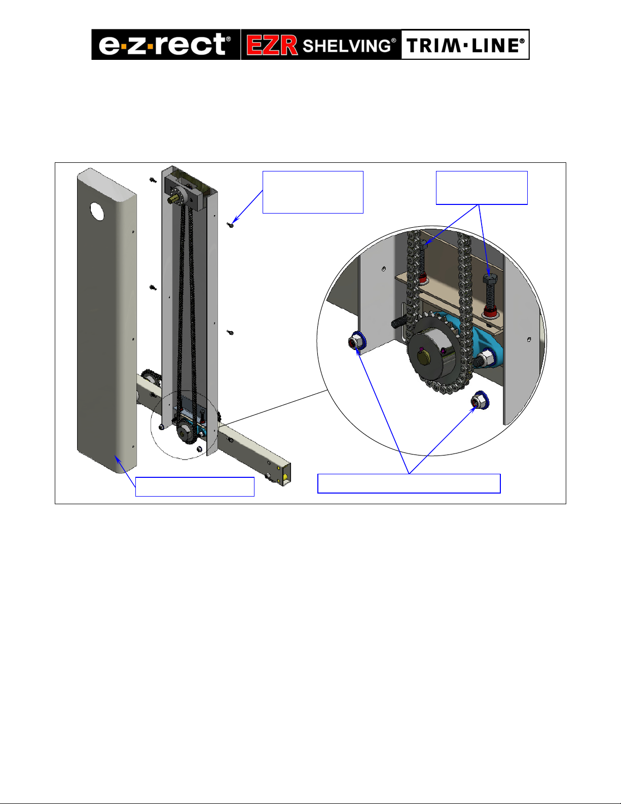
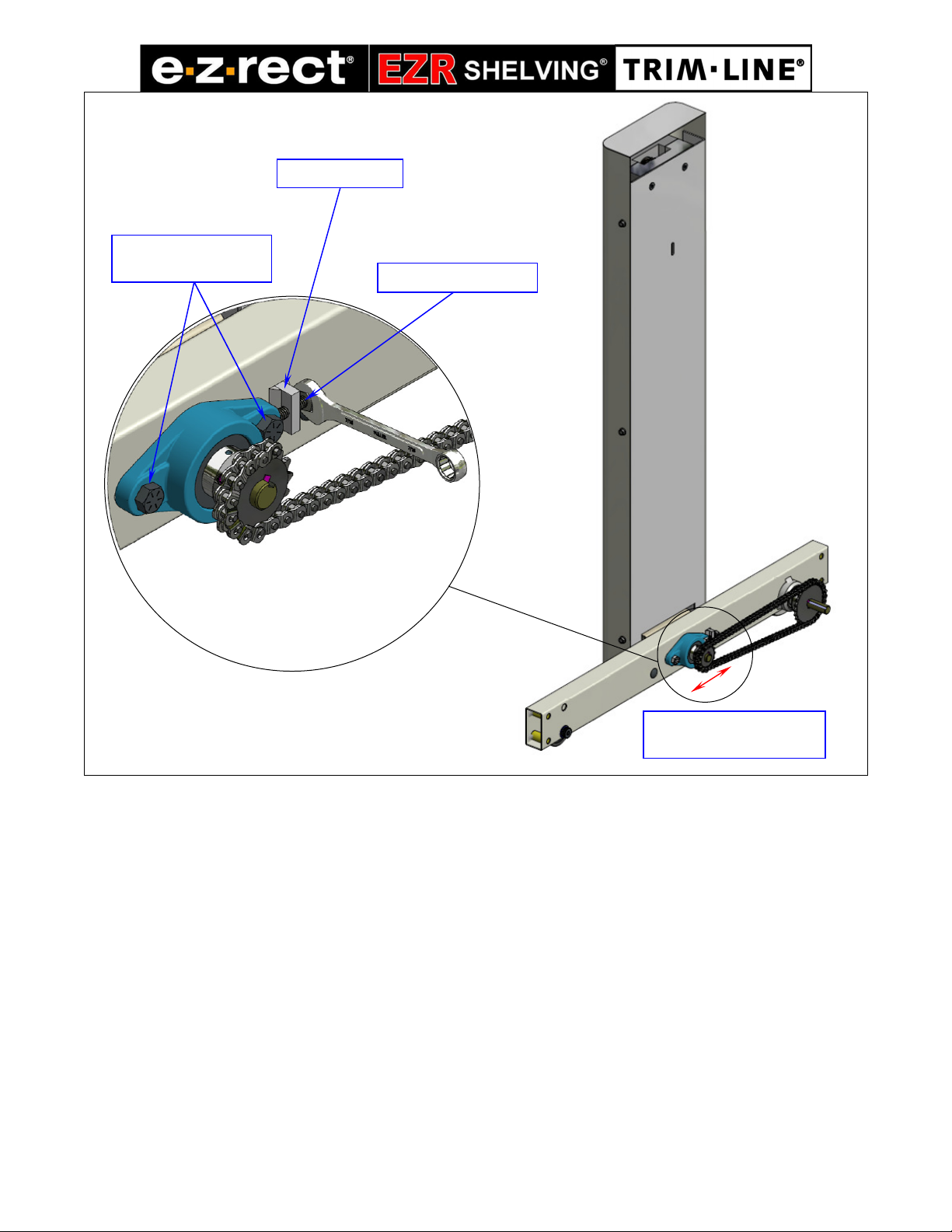
Figure 3: Secure Mechanical Assist to a centre shelving post
5. Replace the casin cover on the mechanical assist unit.
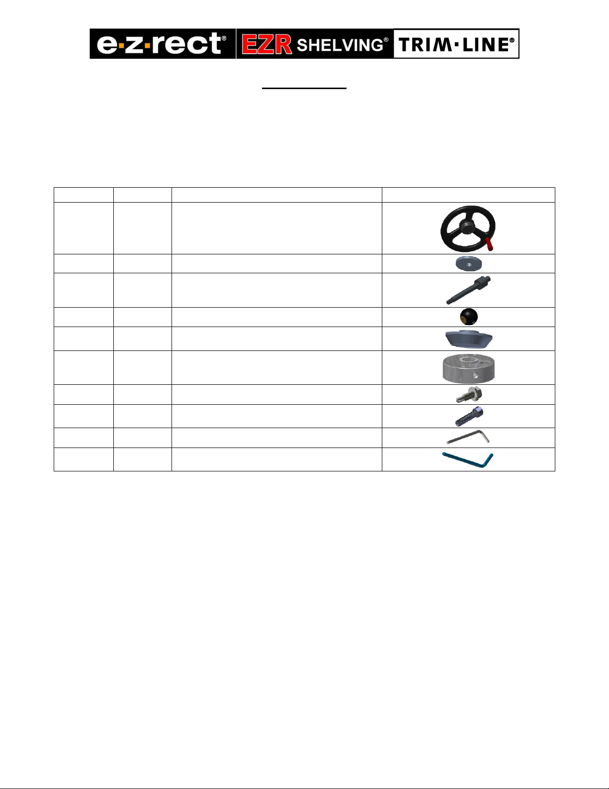
6. In a separate box, labeled Mechanical Assist Drive Handle Assembly, remove the drive handle
installation components consistin of a drive handle assembly, washer rin , lockin pin,
threaded ball knob, centre cap, aluminum hub and three #14 x ¾” tek screws.
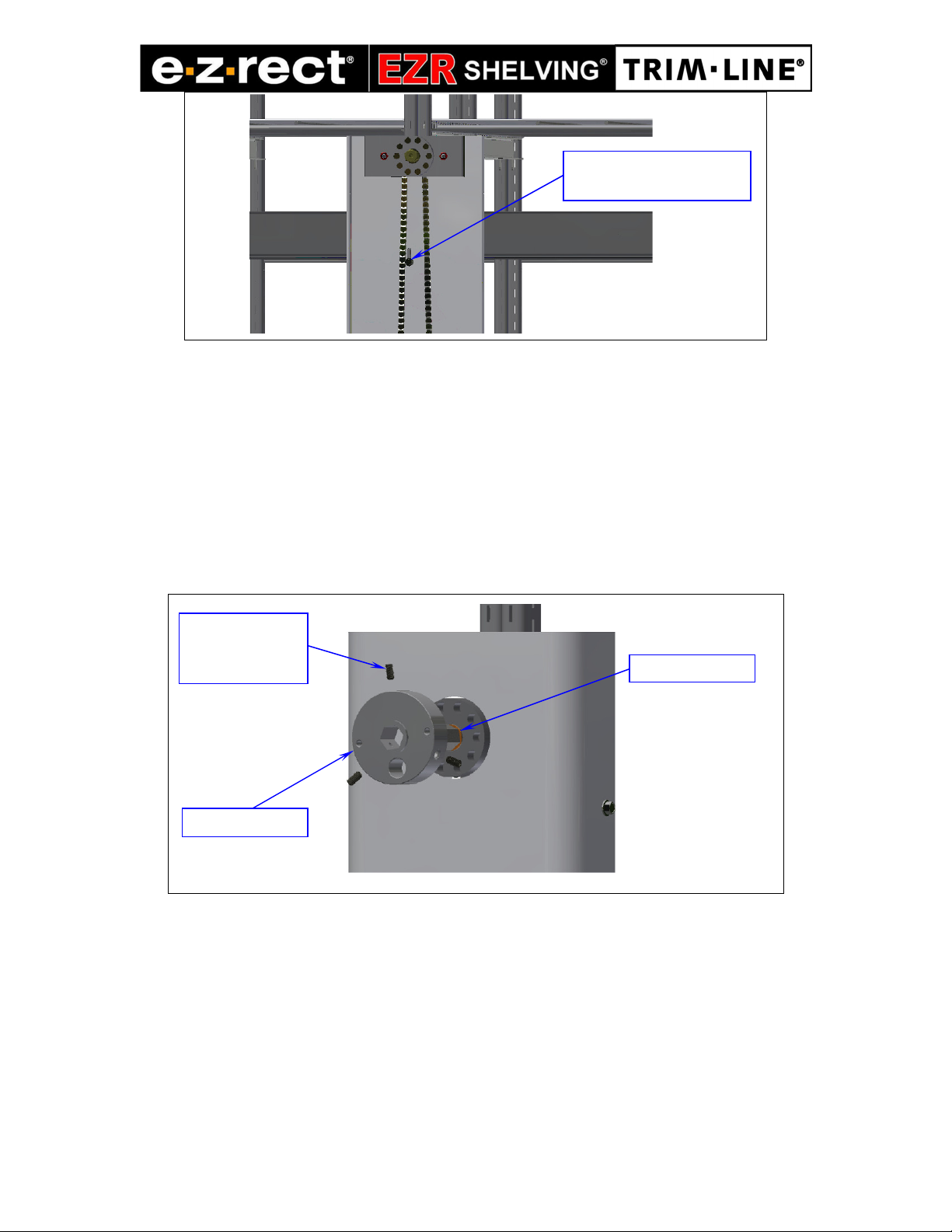
7. Slide the Aluminum Hub onto the drive spindle until it is butted a ainst the retainin rin .
The hub has three socket head setscrews. Usin the supplied Allen key, ti hten the three
setscrews firmly on the shaft. See Figure 4 below
Figure 4: Aluminum Hub installation
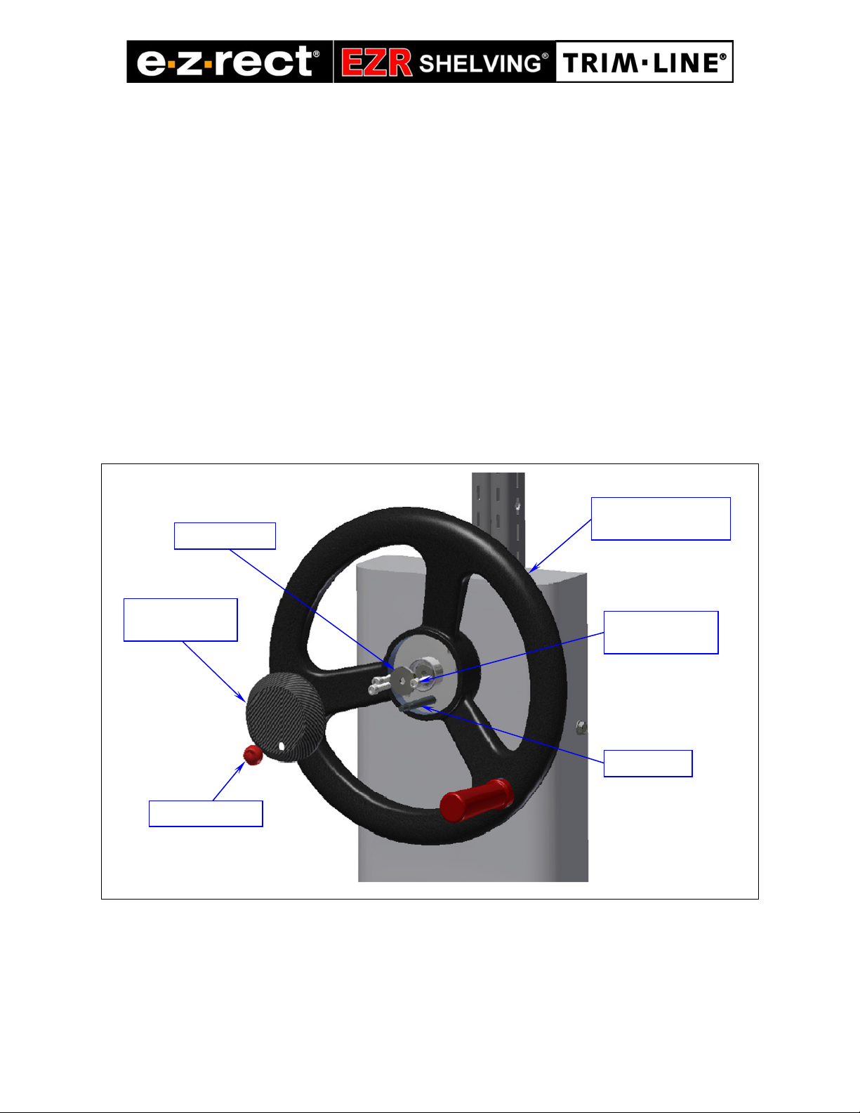
8. Rotate the hub so that the bi hole on it ali ns with one of the Front rank Block holes.
9. Insert the Locking Pin into the bi hole until it bottoms out and the aluminum hub is locked
in.
10.Slide the Drive Handle Assembly onto the drive spindle. Aside from the centre hole, the
drive handle has one lar er and two sli htly smaller holes. The lockin pin fits into the lar er
hole while the two smaller holes should ali n with the threaded holes on the hub.
Secure Mechanical Assist
usin a self-drillin screw
Secure the hub
head setscrews