E3 Cycling F11C User manual

Battery Installation
To help you get started quickly, the computer battery has been installed at the factory. Under
normal usage a battery should last approximately one year. The F11C uses a 3V CR2032
button cell battery, which is available at most camera and electronic shops.
NOTE: Most problems that occur with cyclocomputers are caused by a dead or weak battery.
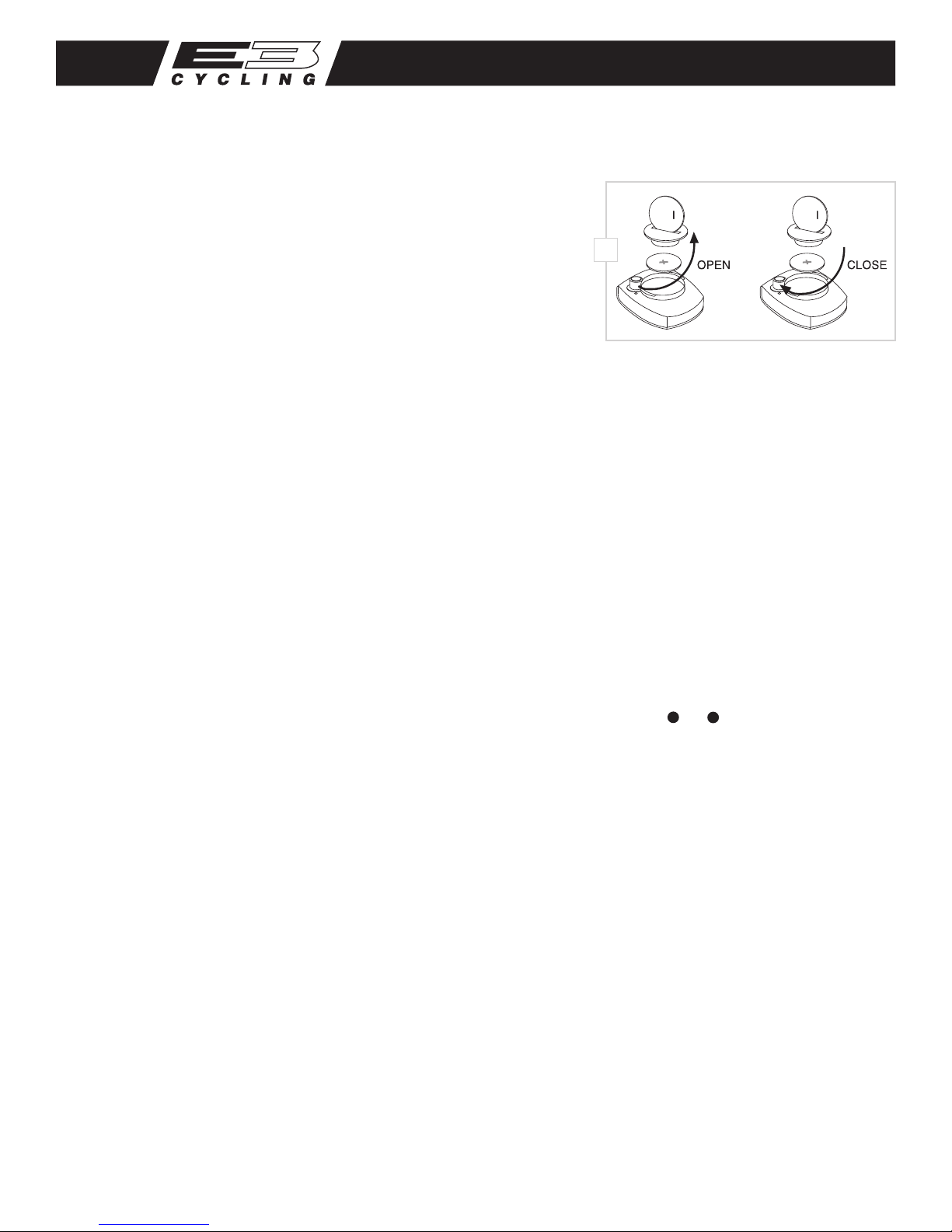
Should you need to replace the battery, follow the steps below.
1. Remove the battery cap from the bottom of the computer using a small coin. See Figure 1.
2. Install the battery in the battery compartment with the positive (+) side facing the battery cap.
3. Reinstall the battery cap and tighten securely. NOTE: During a battery change, all data will be cleared from memory. Make a note of your
current wheel size setting and cumulative odometer mileage before replacing the battery so you can reprogram these values once the new
battery is installed (see “Program Wheel Size”and “Set the Odometer”).
4. If for some reason the screen is blank or shows an irregular display after a battery change, press the reset button on the underside of the
computer head. See Figure 6.
Determine Wheel Size
The F11C uses wheel circumference (measured in millimeters) to calculate speed and distance. Before you can program the F11C you must
calculate wheel circumference using one of the three methods below.
1. Select size from chart (least accurate): Use the chart to nd the circumference for your tire size. The chart lists the programming sizes for some
of the most popular tire sizes currently in use. These numbers are estimations which may not precisely match the circumference of your wheel,
due to variations in tire size between brands and models.
2. Measure wheel diameter (more accurate): Measure your wheel diameter (including wheel and tire) in millimeters (1 inch = 25.4mm) and
multiply by 3.1416. This value is your wheel circumference.
F11C Cycle Computer
c
25
c
25
Thank you for your purchase of an E3™ cycle computer. With all the features that a professional rider needs to keep track of a
ride, the F11C is the perfect accessory for any cyclist. The cadence function makes the F11C an excellent choice for improving road
training as well.
1
Computer Functions
CURRENT SPEED (m/h or km/h)
Displays current speed, up to 105mph (168km/h). Accurate to 0.1m/h
or km/h. Always displayed at the top of the screen.
SPEED DISPLAY BAR
Provides a graphic display of current speed. Additional segments
of bar illuminate as current speed increases.
CLOCK (TIME)
Displays time of day in a 12 hour or 24 hour format.
AUTOMATIC RIDE TIMER (ATM)
Auto start/stop timer is activated by front wheel movement and
records actual ride time up to 9:59:59.
TRIP DISTANCE (DST)
Displays distance traveled during current ride (or since last reset),
up to 999.9 mi. or km.
ODOMETER (ODO)
Displays cumulative ride distance, up to 99,999 mi. or km.
SPEED COMPARISON (56)
Compares current speed to average speed. As you ride, a (5) or (6)
will appear next to current speed to indicate whether
your current speed is above (5) or below (6) your average speed.
This function is automatic, requires no programming and
cannot be disabled.
AVERAGE SPEED (AVG)
Calculates average speed based on ride time (ATM) & trip distance (DST).
MAXIMUM SPEED (MAX)
Displays highest speed attained during a ride (or since last reset), up to
105m/h (168km/h).
STOPWATCH (STP)
Manual stopwatch allows you to time any portion of a ride, up to 9:59:59.
CADENCE (C)
Displays crank revolutions per minute (RPM) from 30 to 240.
DUAL WHEEL SIZE SETTINGS
Wheel circumference is used to calculate speed and distance. The F11C
includes two wheel size settings ( 1and 2), allowing you to switch your
computer between two bikes with dierent wheel sizes (e.g. your road
bike and mountain bike).
AUTO SLEEP
To prolong battery life, the F11C will automatically enter“sleep” mode
after 5 minutes of non-use. The computer will automatically restart as
soon as it receives input from the speed sensor, or when any button is
pressed.
SCAN MODE
Allows hands free viewing of all display screens except Cadence. When
scan mode is activated, the computer will scroll through all display
screens (except Cadence) on a continuous loop, displaying each screen
for two seconds. To activate scan mode, press and hold the LEFT button
for three seconds in any display screen except Cadence. To exit scan
mode, press the LEFT or RIGHT button in any display screen.

3. Perform roll-out test (most accurate): See Figure 2.
STEP 1
Stand your bicycle upright. With your tire inated to its proper pressure,
rotate your front wheel so that the valve is located at the bottom (6
o’clock position). Make a mark on the oor to indicate the valve location.
STEP 2
Roll the bicycle forward in a straight line for one complete wheel
revolution, until the valve is again at the bottom (ideally, you should be
on the bike). Make a mark on the oor to indicate the valve location.
STEP 3
Measure the distance between the marks in millimeters
(1 inch = 25.4mm). This value is your wheel circumference.
Program the Computer
Before using your F11C, you must program wheel size (see “Determine
Wheel Size,” above), select a speed scale (miles or kilometers), set the
odometer (if desired), input your weight and set the clock. The rst step
is to select the speed scale.
Select Miles or Kilometers, Program Wheel Size
& Set the Odometer
The F11C is capable of displaying speed and distance information
in either miles or kilometers. Also, the odometer can be set so
that cumulative mileage can be restored after a battery change or
transferred from another computer.
(SELECT MILES OR KILOMETERS)
STEP 1
Press the RIGHT button to advance to the Odometer display screen
(ODO). In the Odometer display screen (ODO), press and hold the RIGHT
button for three seconds.
STEP 2
“km/h”or “m/h” will appear on the right side of the screen. Press the LEFT button to select miles (m/h) or kilometers (km/h).
STEP 3
Press the RIGHT button to conrm your selection and advance to the wheel size setting screen.
(PROGRAM WHEEL SIZE)
STEP 4
After the speed scale has been selected, the computer will automatically advance to the rst wheel size programming screen ( 1). The digit at the
right of the screen will ash. Press the LEFT button to adjust the ashing digit according to the wheel circumference value determined above.
Press the RIGHT button to advance to the next ashing digit.
STEP 5
Repeat this sequence until the correct wheel size has been entered. Then press the RIGHT button to advance to the second wheel size setting
screen ( 2).
STEP 6
The digit at the right of the screen will ash. Press the LEFT button to adjust the ashing digit. Press the RIGHT button to advance to the next
ashing digit.
STEP 7
Repeat this sequence until the second wheel size has been entered. Then press the RIGHT button to advance to the odometer setting screen.
(SET THE ODOMETER)
STEP 8
After programming wheel size, the computer will automatically advance to the odometer setting screen. (If you don’t want to change the
odometer setting, press the RIGHT button ve times to exit the set-up mode.) The digit at the right of the screen will ash. Press the LEFT button
to adjust the value. Press the RIGHT button to advance to the next ashing digit.
STEP 9
Repeat this sequence until the odometer has been set to the appropriate value. Then press the RIGHT button to exit the set-up mode and return
to the Odometer display screen.
16 x 1.75
20 x 1.75
26 x 0.75
24 x 1.75
24 x 1
1272
1590
1948
1907
1954
26 x 1.0
26 x 1.6
26 x 1.5
26 x 1
1973
2105
2026
2051
26 x 1.75
26 x 2
26 x 2
26 x 1.9
2070
2089
2114
2133
TIRE SIZE CIRCUMFERENCE
1/8
3/8
3/8
27 x 1
28 x 1.5
28 x 1
28 x 1
28 x 1.75
2199
2224
2268
2265
2205
700 x 18c
700 x 25c
700 x 23c
700 x 20c
2102
2114
2133
2146
700 x 28c
700 x 40c
700 x 37c
700 x 32c
2149
2174
2205
2224
TIRE SIZE CIRCUMFERENCE
3/8
1/2
1/4
1x
Distance in mm / inch
2

Input Weight
The F11C uses body weight to estimate calories and fat burned during a ride.
STEP 1
Press the RIGHT button to advance to the Stopwatch display screen (STP). In the Stopwatch display screen (STP), press and hold the RIGHT button
for three seconds. “Lb”or “Kg”will ash in the lower line of the display. Press the LEFT button to select pounds (Lb) or Kilograms (Kg). Press the
RIGHT button to conrm your selection and advance to the weight input screen.
STEP 2
The right digit will ash. Press the LEFT button to adjust the value. Press the RIGHT button to advance to the next ashing digit.
STEP 3
Repeat this sequence until you have entered your correct weight. Then press the RIGHT button to exit the set-up mode and return to the
Stopwatch display screen.
Set the Clock
The F11C is equipped with a digital clock that displays time of day in a 12 hour or 24 hour format.
STEP 1
Press the RIGHT button to advance to the CLOCK display screen (TIME). In the Clock display screen (TIME), press and hold the RIGHT button for
three seconds.
STEP 2
“12” or “24”will ash in the lower line of the display. Press the LEFT button to select 12 hour or 24 hour mode. Press the RIGHT button to conrm
your selection and advance to the hours setting.
STEP 3
The hours will ash. Press the LEFT button (or press and hold) to advance the hours. Press the RIGHT button to advance to the minutes setting.
STEP 4
The minutes will ash. Press the LEFT button (or press and hold) to advance the minutes. Press the RIGHT button to set the time and return to the
Clock display screen.
Installation
We recommend that you install your F11C in the following manner, starting with the sensor units on the chainstay and working up to the
mounting bracket on the handlebar.
WHEEL MAGNET AND SENSOR INSTALLATION
STEP 1
Identify the two sensors and magnets. The cadence sensor is connected to the shorter cable and has“CADENCE” printed on one side. The
cadence magnet is the square, at magnet with “CADENCE MAGNET” molded on one side.
STEP 2
Using two zip-ties, mount the cadence sensor loosely (so that you can slide it around) to the outside of the left (non-drive side) chainstay. See Figure 3.
STEP 3
Use an included zip-tie to attach the cadence magnet loosely to the inside of the left crank arm directly opposite the cadence sensor.
The words on the magnet should face the sensor. Adjust the position of the magnet and sensor until the magnet passes the sensor with
1mm-3mm of clearance.
STEP 4
Using two more zip-ties, mount the speed sensor loosely (so that you can slide it around) to the inside of the left (non-drive side) chainstay. See Figure 3.
STEP 5
Attach the wheel magnet loosely to one of the spokes on the same side of the wheel as the sensor. Adjust the position of the magnet and sensor
to achieve 1-3mm of clearance between the two (1mm is about the thickness of a penny). See Figure 3. If the magnet and sensor are not close
enough, the computer will not pick up a reading or readings will be inconsistent and erratic. Most problems that occur when installing a new
computer are related to magnet and sensor alignment and spacing.
STEP 6
Once the speed and cadence sensors and magnets are aligned properly, tighten the zip-ties to secure all four in place and trim the excess zip-tie
ends with scissors.
STEP 7
Route the sensor cable along the frame toward the handlebar, securing it with zip-ties or electrical tape to ensure it does not contact or interfere
with the crank or wheels in any way. Be sure to leave enough slack in the cable to allow for the movement of the handlebar while steering, and
the motion of the suspension fork if your bike is equipped with one.

Tech Support 1(800)553-8324
0408_4
Made in China
STEP 8
Wrap the excess sensor cable around the front brake cable housing, securing with electrical tape as
necessary. When nished, enough cable slack should remain for the computer mounting bracket to reach
the handlebar. Check to make sure that all excess sensor cable is either taped down or wrapped around the
brake cable housing so that nothing can snag it during a ride.
BRACKET INSTALLATION
Remove the backing from the small, adhesive rubber pad and apply the pad to the underside of the
mounting bracket. Use two zip-ties to attach the bracket to the handlebar as shown in Figure 4. Once
the bracket is securely installed, trim the excess zip-tie ends with scissors.
COMPUTER HEAD INSTALLATION
Place the computer head in the bracket and twist the head clockwise until you hear a ‘CLICK’, indicating
that the unit is locked in the bracket. See Figure 5. To remove the computer head, twist the head
counterclockwise and then lift it out of the bracket.
TEST OF INSTALLATION
Once installation is complete, test the unit to make sure everything is adjusted and working properly.
STEP 1
Install the computer head in the handlebar bracket and press the RIGHT button to advance to the Cadence
(C) display screen.
STEP 2
Lift the rear of the bicycle and turn the cranks. The computer should register a speed reading and cadence
reading within 1-2 seconds. If it does not, check the alignment of the speed and cadence magnets with the
sensors. Make sure the space between the magnets and sensors is 3mm or less. Adjust as necessary and
re-test.
Select Wheel Size
When switching your computer between bikes with dierent wheel sizes, don’t forget to select the
appropriate wheel size setting ( 1or 2) for each bike. In the Average Speed display screen (AVG), press and
hold the RIGHT button for three seconds to change between wheel size 1and wheel size 2.
Using the Stopwatch
STEP 1
In the Stopwatch display screen (STP), press the LEFT button to start the Stopwatch. Press the LEFT button
again to stop the Stopwatch. While the Stopwatch is running, the computer will calculate an estimate of
Calories burned and Fat burned during the timed session.
STEP 2
When the Stopwatch is stopped, Stopwatch time, Calories burned (C) and Fat burned (Lb or Kg) will be
displayed in a continuous loop. Remember that Calories burned and Fat burned are only calculated while
the Stopwatch is running.
STEP 3
To reset the Stopwatch, advance to the Stopwatch display screen (STP) and press and hold both the LEFT and RIGHT buttons for four seconds.
Reset Display Screens
The ATM, DST, AVS and MAX display screens are reset simultaneously. In the Automatic Ride Timer display screen (ATM), press and hold both the
LEFT and RIGHT buttons for four seconds to reset the data in all four screens.
The Stopwatch is reset independently. In the Stopwatch display screen (STP), press and hold both the LEFT and RIGHT buttons for four seconds
to reset the Stopwatch.
Maximum Speed can also be reset independently. In the Maximum Speed display screen (MAX), press and hold both the LEFT and RIGHT buttons
for four seconds to reset Maximum Speed.
To reset ALL display screens and ALL programmed settings (including Clock, Odometer, wheel size settings and weight), depress the reset button
on the underside of the computer head. See Figure 6.
4
LOCK
UNLOCK
5
6
3
cadence
1-3mm
1-3mm
speed
Table of contents
Popular Bicycle Accessories manuals by other brands

THM Carbones
THM Carbones THM FRONTALE Instruction book

Silva
Silva 37313-2 Full version manual

Ceramicspeed
Ceramicspeed Oversize Pulley Wheel System Mounting & Maintenance

Bosch
Bosch Active Line Plus Series Original operating instructions

Sigma
Sigma BUSTER 600 manual

Specialized
Specialized Snell Helmet owner's manual