6
4.3.Installationon HIGHWAY
OpenyourAmigacomputerhousing(seeyourcomputer'smanualfor
detailedinstructions)byremovingtheholdingscrewsonthebackand/
orthesides.Afterwards,theupperpartofthehousingcaneasilybe
removed.
RemovethefromitsZorroslotandputitonthetable,withthe
SMDpartslookingupwards.TheZorroconnectorshouldfacetoyou,
theUSBconnectortotheright.
HIGHWAY
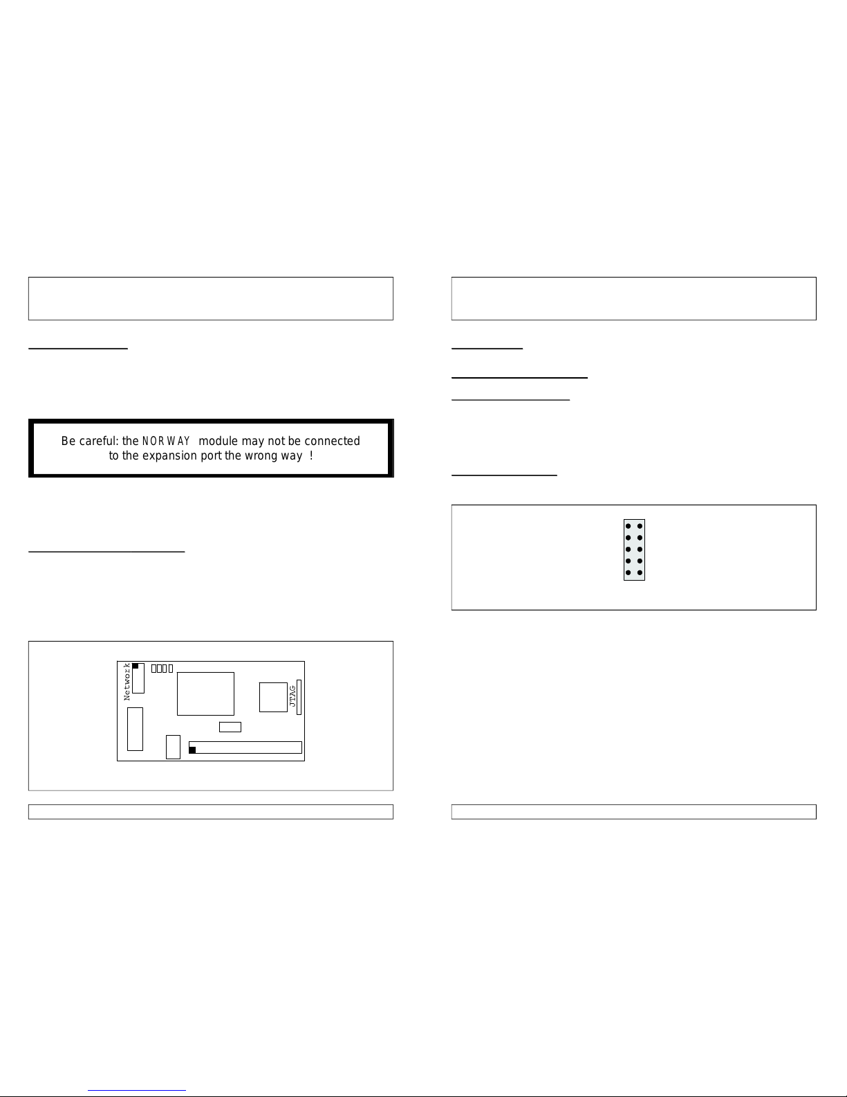
[Fig.2]Connectionofand(topside/frontsideview).HIGHWAY NORWAY
JTAG
ZorroConnector
1
1Expansionport
StatusLEDs
NIC
redcable
Theisnowattachedtotheexpansionportofthe
withtheSMDpartsfacingdownwards.Pleasecheckcarefullythat
bothconnectorsfitperfectlyandthat
.
Misplacingthecanleadtodamages.
Insertthe/combicardintoitsZorroslot.
NORWAY
NORWAY
NORWAY
HIGHWAY
HIGHWAY
nopinsareleftoveronany
side
NORWAY
7
4.4.Connectingthenetworkcable
4.5.StatusLEDs
Thesmallsizeoftheopensmanypossibilitieswhereto
placetheSUBD9connectorcarryingthenetworksignals.
Connectthe10pinfemaleconnectorwiththeflatribboncable(see
figure2)tothe.Theredcablemustfaceawayfromthe
card.Nowfixtheholdingplateinafreeslot.Youalsocan
mountthisconnectorinaspareplateposition(likeintheA4000CPU
plateonthebackside).Placetheenclosedsticker“Ethernet”nextto
theconnectortoavoidconfusionwhenconnectioncables!
TheSUBD9toRJ45adaptorenclosedinyourpackageisnow
connectedtotheholdingplateyoujustmounted.Fixatetheadaptor
withitsscrewstogetasecureconnectiontothenetwork.
Yourtwistedpairnetworkcablecandirectlybeconnectedtothe
adaptor.Useanormal,straightforwardcableforconnectionstohubs
orswitches.Foradirectconnectionbetweentwocomputersa
crossovercableisneeded.Bothcabletypesshouldbeonstockatyour
computerdealer.
CloseyourcomputerbeforereconnectingtheACpowercable.
IYourisequippedwithfourLEDswhichallowcontrolof
networktraffic.Theyarelocatedbetweenthenetworkconnectorand
theNIConthemodule.
TheLEDsshowthefollowingsignal(lefttoright):
TX.......green.......Datatransfertonetwork
RX.......green.......Datatransferfromnetwork
COL......red.........Collision
LNK......orange......Carrierfound
NORWAY
NORWAY
NORWAY
NORWAY
HIGHWAY
NORWAY