EA3GCY EGV-9B BPFLPF User manual

EGV-9B_BPFLPF module for EGV-9B CW Transceiver kit Page 2
INTRODUCTION
EGV-9B_BPFLPF
The EGV-9B_BPFLPF is the 3 to 30MHz filter plug-in module for the EGV-9B 9-band CW transceiver.
This module incorporates 5 7-pole low-pass filters and two variable band-pass filters and one band-pass
filter. All the filters are switched by means of relays to avoid their interactions.
Note: good experience on radio assembly is required.
It shouldn't be your first transceiver to build.
All SMD parts soldered at the factory. You don't have to solder anything SMD
SPECIFICATIONS
RX BAND-PASS FILTER:
Power requirements: 12 –14VDC
Antenna impedance: 50 ohms nominal.
Frequency:
1) Fixed filter for 80m
2) Variable filter from 60 to 30m
3) Variable filter from 20 to 10m
LOW PASS FILTER:
Filters: 80m, 60-40m, 30-20m, 17-15m and 12-10m
Harmonics output: -45dBc or better below the fundamental frequency (excepted 60, 17 and 12m)
Other spurious signals: -50dBc or better below the fundamental frequency.
60, 17 and 12m bands: The attenuation of harmonics signals are not so good.
Switching: Relays.
Board dimensions: 100 x 100 mm.
PLEASE READ ALL ASSEMBLY INSTRUCTIONS COMPLETELY AT
LEAST ONCE BEFORE YOU BEGIN.

EGV-9B_BPFLPF module for EGV-9B CW Transceiver kit Page 3
COMPONENT LIST
Resistors
Checked
Ref.
Value
Ident./Comment
Located
R1
220 Ω
Top layer
R2
220K
Top layer
R3
220K
Top layer
R4
220K
Top layer
R5
220K
Top layer
R6
220K
Top layer
R7
220K
Top layer
Potentiometer
P1
50K
50K shaft potentiometer 50K 503
Top layer
Capacitors
Checked
Ref.
Value
Ident./Comment
Located
C1
470p
SMD capacitor NP0 or CG0 100V
Bottom layer
C2
1200p
SMD capacitor NP0 or CG0 100V
Bottom layer
C3
1200p
SMD capacitor NP0 or CG0 100V
Bottom layer
C4
470p
SMD capacitor NP0 or CG0 100V
Bottom layer
C5
270p
SMD capacitor NP0 or CG0 100V
Bottom layer
C6
680p
SMD capacitor NP0 or CG0 100V
Bottom layer
C7
680p
SMD capacitor NP0 or CG0 100V
Bottom layer
C8
270p
SMD capacitor NP0 or CG0 100V
Bottom layer
C9
180p
SMD capacitor NP0 or CG0 100V
Bottom layer
C10
390p
SMD capacitor NP0 or CG0 100V
Bottom layer
C11
390p
SMD capacitor NP0 or CG0 100V
Bottom layer
C12
180p
SMD capacitor NP0 or CG0 100V
Bottom layer
C13
82p
SMD capacitor NP0 or CG0 100V
Bottom layer
C14
220p
SMD capacitor NP0 or CG0 100V
Bottom layer
C15
220p
SMD capacitor NP0 or CG0 100V
Bottom layer
C16
82p
SMD capacitor NP0 or CG0 100V
Bottom layer
C17
56p
SMD capacitor NP0 or CG0 100V
Bottom layer
C18
150p
SMD capacitor NP0 or CG0 100V
Bottom layer
C19
150p
SMD capacitor NP0 or CG0 100V
Bottom layer
C20
56p
SMD capacitor NP0 or CG0 100V
Bottom layer
C21
100n
SMD capacitor 50V
Bottom layer
C22
100n
SMD capacitor 50V
Bottom layer
C23
100n
SMD capacitor 50V
Bottom layer
C24
100n
SMD capacitor 50V
Bottom layer
C25
100n
SMD capacitor 50V
Bottom layer
C26
100n
SMD capacitor 50V
Bottom layer
C27
100n
SMD capacitor 50V
Bottom layer
C28
2p7
SMD capacitor 50V
Bottom layer
C29
4p7
SMD capacitor 50V
Bottom layer
C30
390p
SMD capctiro 50V
Bottom layer
C31
390p
SMD capacitor 50V
Bottom layer
C32
33p
SMD capacitor 50V
Bottom layer
Note: All SMD places allow 0603, 0805, 1206 or 1210 format

EGV-9B_BPFLPF module for EGV-9B CW Transceiver kit Page 4
Semiconductors
Checked
Ref.
Type
Ident./Comment
Located
Printed “D”
8 x diodes printed D are 1N4148 (vertically mounted)
Top layer
Printed “DV”
All diodes printed DV are BB201 SMD (bottom layer PCB)
Bottom layer
D1
10V zener 0.5W
10V
Top layer
Inductors/RF Transformers/Relay
Checked
Ref.
Value/Type
Ident./Comment
L1
5u3H 3334
34 Shielded coil
Top layer
L2
5u3H 3334
34 Shielded coil
Top layer
L3
5u3H 3334
34 Shielded coil
Top layer
L4
5u3H 3334
34 Shielded coil
Top layer
L5
1u2H 3335
35 Shielded coil
Top layer
L6
1u2H 3335
35 Shielded coil
Winding toroids (see text)
Turns (0.4 wire)
L7
T37-2
Red toroid
25 turns
L8
T37-2
Red toroid
27 turns
L9
T37-2
Red toroid
25 turns
L10
T37-2
Red toroid
18 turns
L11
T37-2
Red toroid
20 turns
L12
T37-2
Red toroid
18 turns
L13
T37-6
Yellow toroid
15 turns
L14
T37-6
Yellow toroid
16 turns
L15
T37-6
Yellow toroid
15 turns
L16
T37-6
Yellow toroid
12 turns
L17
T37-6
Yellow toroid
14 turns
L18
T37-6
Yellow toroid
12 turns
L19
T37-6
Yellow toroid
10 turns
L20
T37-6
Yellow toroid
11 turns
L21
T37-6
Yellow toroid
10 turns
Relays
RL1 to RL3
EA2-12NJ
EA2- 12NJ (NEC or KEMET)
--
RL4 to RL13
G5V-1 12V
Omron G5V-1 12V
--
Hardware
Checked
Qty/Ref.
Type/Comment
Located
1 BNC socket
BNC socket
Top layer
8 pins strip
8 pins extra long strip (LPF switching)
Top layer
6 pins strip
6 pins extra long strip (BPF switching)
Top layer
3 pins strip
3 pins strip “V-TUNE”
Top layer
4 10mm spacers
4 pcs 10mm metal spacers
Top layer
4 M3 nuts
4 pcs. M3 nuts
Top layer
4 M3x10
4 pcs. M3 x 10mm screws
Bottom layer
4 M3x4
4 pcs. M3 x 4 or 5mm screws
Top layer
400 cm
400 cm enamelled wire 0,4mm
--

EGV-9B_BPFLPF module for EGV-9B CW Transceiver kit Page 5
RECOMMENDED ASSEMBLY SEQUENCE
All SMD parts soldered at the factory. You don't have to solder anything SMD
Based on your experience you can place the components in the order you are used to.
However I can recommend the following assembly sequence:
Place and solder D1 10V zener diode.
Insert and solder all resistors
Insert and solder the other eight diodes (1N4148) all printed “D” on PCB. They are all placed
vertically (see the images).
Insert and solder all shielded coils (make sure they lie flat on the board). L1 to L4 are 5u3H
marked 34. L5 and L6 are 1u2H marked 35.
Insert and solder toroids (see section “TOROIDS WINDNG”).
Place and solder all relays. RL1, RL2 RL3 have a printed line that has to match the one printed
on the board (see the images).
Place and solder BNC antenna socket.
To finish, solder the pins strips. This is important work. See the section “wiring and connections”
All capacitors are SMD format and are soldered in bottom PCB by www.ea3gcy.com lab.

EGV-9B_BPFLPF module for EGV-9B CW Transceiver kit Page 6
TOROIDS WINDING
The following table shows the type of toroid, the turns it has to wind and the length of wire it will
need. All toroids are 9.5mm/0.375in outside diameter. The T37-2 toroid is the red one and the T37-6 is
the yellow one. 0.4 mm thick enameled wire is used.
TOROIDS TABLE
TOROID
BAND
TYPE
TURNS
WIRE lenght (0.4mm Ø)
L7
80
T37-2
25
36 cm
L8
80
T37-2
27
39 cm
L9
80
T37-2
25
36 cm
L10
60-40
T37-2
18
28 cm
L11
60-40
T37-2
20
30 cm
L12
60-40
T37-2
18
28 cm
L13
30-20
T37-6
15
24 cm
L14
30-20
T37-6
16
25 cm
L15
30-20
T37-6
15
24 cm
L16
17-15
T37-6
12
20 cm
L17
17-15
T37-6
14
23 cm
L18
17-15
T37-6
12
20 cm
L19
12-10
T37-6
10
18 cm
L20
12-10
T37-6
11
19 cm
L21
12-10
T37-6
10
18 cm
Note: Lengths are calculated so that you will have some wire left over and easy to pull on.

EGV-9B_BPFLPF module for EGV-9B CW Transceiver kit Page 7
TOROIDS ASSEMBLY EXAMPLE:
The following example is the low pass filter for 40m
40m LPF Toroids L10, L11 and L12
L10 and L12 are identical and are wound with 18 turns.
L11 is wound with 20 turns.
They use T37-2 (red toroids 9.5mm/0.375in outer diameter).
Cut about 28cm (10.3”) of 0.4mm diameter enameled wire and wind the L10 and L11 toroids with
eighteen (18) turns. Spread the turns evenly around the toroid and wind them tightly so that they follow
the contour of the toroid and are as tight against the toroid as possible. The turns should be evenly
distributed around the circumference of the toroid.
Leave pigtails of about 10-12mm (0.70”). Scrape off the enamel with a knife from the ends of the wire, in
order to solder the toroid onto the board.
For L11 cut about 30cm (12”) of 0.5mm diameter enameled wire and wind twenty (20) turns.
Mount and solder the three toroids in place.
Counting the turns: Count one turn for each pass of the wire through the center of the toroid.
Important: Wind the toroid exactly as shown in the images. One turn more or less will affect the
transmitter spectrum and the output power.

EGV-9B_BPFLPF module for EGV-9B CW Transceiver kit Page 8
L10 (18 turns) L11 (20 turns) L12 (18 turns)
PLUG IN MODULE - WIRING AND CONNECTIONS
The EGV-9B_BPFLPF PCB is a plug-in module that sits on top of the EGV-9B's main board.
The connection is simple, but requires special attention so that errors do not arise.
1.- The three-pin “V-TUNE” strip goes up and is soldered to the bottom side of the board.
2.- The other two strips of pins go down (to connect to the main board) and are soldered to the top
side of the board. Extra-long strips of pins are used. 8 extra-long pins strip for LPF switching and 6
extra-long pins strip for BPF switching.
Before soldering you should pay close attention to how tall the pins should be to accommodate the
position of the plug-in board.
Insert the pins from above the board (Top)
Next put the board in place no solder the pins.
Insert the pins into the female sockets of the main board all the way down.
With a fine soldering iron tip, solder the pins on the top of the board.
Although it is not necessary, you can later tear off the plastic strip

EGV-9B_BPFLPF module for EGV-9B CW Transceiver kit Page 9
See the following pictures:
The spacers to screw the board are 10mm and you have to add a nut to gain about 2mm in height.
To fasten to the main board, 10mm (M3x10) screws are used and to fasten the plug-in filter module, 4 or
5mm (M3x4) screws are used.
See the images.

EGV-9B_BPFLPF module for EGV-9B CW Transceiver kit Page 10
SETTINGS AND TESTS
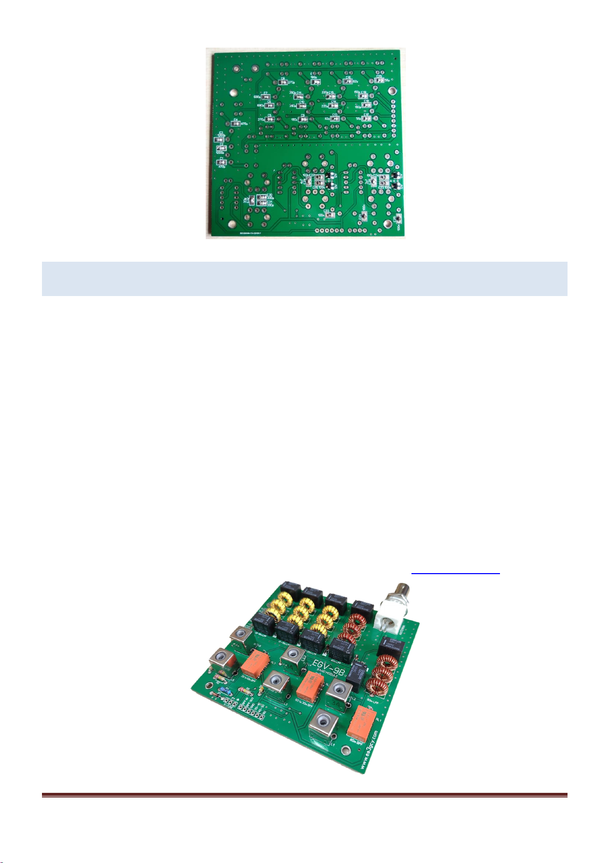
Please, refer to the EGV-9B main board manual for L1 to L6 adjustment and checks.
LIMITED WARRANTY
Please read carefully BEFORE building your kit
All electronic components and hardware
supplied with the kit are under warranty in case
of any manufacturing defect for the period of one
year after purchase. The warranty does not
include the transmitter final amplifier transistor.
The original purchaser has the option of
examining the kit and manual for 10 days. If,
within this period, the buyer decides not to build
the kit, he/she may return the entire
unassembled kit at their own expense for the
shipping expenses. The shipping expenses and
sales commissions (i.e. bank, Ebay, and PayPal
commissions) included in the purchase price will
not be returned.
Please, BEFORE returning a product, request
Javier Solans, EA3GCY, warrants this device to
function according to the specifications, provided
that it is assembled and adjusted as described in
this documentation, and used correctly
according to all provided instructions.
It is your responsibility to follow all the
instructions in the manual, to identify all the
components correctly, and to use good
workmanship and proper tools and instruments
in the construction and adjustment of this kit.
REMEMBER: This kit will not work as a
commercially manufactured product; however, it
can often give similar results. Do not expect
great performance, BUT YOU ARE SURE TO
HAVE LOTS OF FUN!
If you believe that there is a missing kit
component, please do a thorough inventory of
all parts using the parts list in the manual. Check
all bags, envelopes and boxes carefully. If
needed, you may email me and I will replace
any component that you are missing. Even if you
can find the exact part locally, please let me
know so that we are aware of the problem to
help other customers.
I can also supply any part that you have lost,
damaged or broken accidently.
If you find any errors in this manual or would like
to make a comment, please do not hesitate to
THANK YOU for building the
EGV-9B_BPFLPF module kit.
Enjoy QRP!
73 Javier Solans, EA3GCY

EGV-9B_BPFLPF module for EGV-9B CW Transceiver kit Page 11
SCHEMATICS

EGV-9B_BPFLPF module for EGV-9B CW Transceiver kit Page 12
Table of contents
Popular Control Unit manuals by other brands

RIDGE RYDER
RIDGE RYDER 629924 owner's manual

FlowCon
FlowCon Green Installation and operation instruction

Accton Technology
Accton Technology EM4601-SX-SC Quick installation guide

iseg
iseg EHS Series manual

Red Valve
Red Valve Tideflex Series Installation, operation and maintenance manual

Hach
Hach SC4200c User instructions