&,1*44)8*7;.(*6:.52*39&,1*5*(@&3)*9&.1.851&>&7*).;.8.4384+&,1*74:5A'>9-*&,1*74:5
• 100 Industrial Boulevard, Clayton, Delaware 19938-8903 U.S.A. • www.eaglegrp.com
• Phone: 302/653-3000 • (Foodservice/SpecFAB®) 800/441-8440 • (MHC/Retail) 800/637-5100
• Fax: 302/653-2065
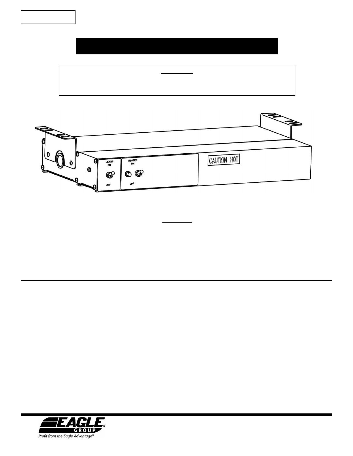
RedHots®
Heat Lamps
WARRANTY
&,1* 44)8*7;.(* 6:.52*39 <&77&398 94 9-* 47.,.3&1 4<3*7 9-&9 ,44)8 8:551.*)
-*7*:3)*72&3:+&(9:7*)'>&,1*44)8*7;.(*6:.52*39<.11'*+7**+742)*+*(98.3
2&9*7.&18&3)<4702&38-.5+47&5*7.4)4+one year +742)&9*4+47.,.3&1.389&11&9.43349
94 *=(**) 2439-8 +742 )&9* 4+ 8-.52*39 +742 9-* +&(947> &,1* 44)8*7;.(*
6:.52*39<.117*51&(*<.9-4:9(-&7,*&3>)*+*(9.;*5&79847(42543*392&9*7.&1:543
)*243897&9.4394.988&9.8+&(9.439-&9&'7*&(-4+<&77&39>).)349*=.89
1*&8*7*+*794&9&14,*(9.43+47&1.89.3,4+9-*&:9-47.?*)5&798&3)8*7;.(*
(*39*783*&7>4:47(&119-*+&(947>+47&88.89&3(*
-.8<&77&39>)4*8349(4;*7&3>(489&884(.&9*)<.9-2&.39*3&3(*2.8:8*&':8*
.25745*7 .389&11&9.43 5.149 1.,-9 &)/:892*398 5.149 4:9&,* .25745*7 ;*39.1&9.43
&)/:892*398 &19*7&9.43 (&1.'7&9.43 <743, ;419&,* <743, ,&8 ;419&,* 47 ,&8
(43;*78.438 7*8*99.3, 4+ (.7(:.9 '7*&0*78 47 8&+*9> (4397418 4;*79.2* (-&7,*8 97&;*1
(-&7,*8435479&'1**6:.52*392.1*&,*.3*=(*884+2.1*845*7&9.43(4397&7>94
9-*.389&11&9.43&3)45*7&9.3,.3897:(9.438)&2&,*(&:8*)'>+144)+.7*47&(984+4)
-.8<&77&39>8-&11349&551>.+9-*3&2*51&9*-&8'**37*24;*)47&19*7*)
-*7*&7*34<&77&39.*8<-.(-*=9*3)'*>43)9-*8*<&77&39.*81149-*7*=57*88*)
47 .251.*) <&77&39.*8 .3(1:).3, 9-48* 4+ 2*7(-&39&'.1.9> 47 +.93*88 +47 & 5&79.(:1&7
5:7548* <-.(- *=(**) 9-* <&77&39.*8 89&9*) &'4;* &7* ).8(1&.2*) '> &,1*
44)8*7;.(*6:.52*39&3)*=(1:)*)+7429-.8&,7**2*394*2514>**47&,*394+
4:78 -&8 &3> &:9-47.9> 94 2&0* &3> 7*57*8*39&9.43 47 <&77&39> <-.(- *=(**)8 9-*
<&77&39.*889&9*)&'4;*
! $ # "
%!