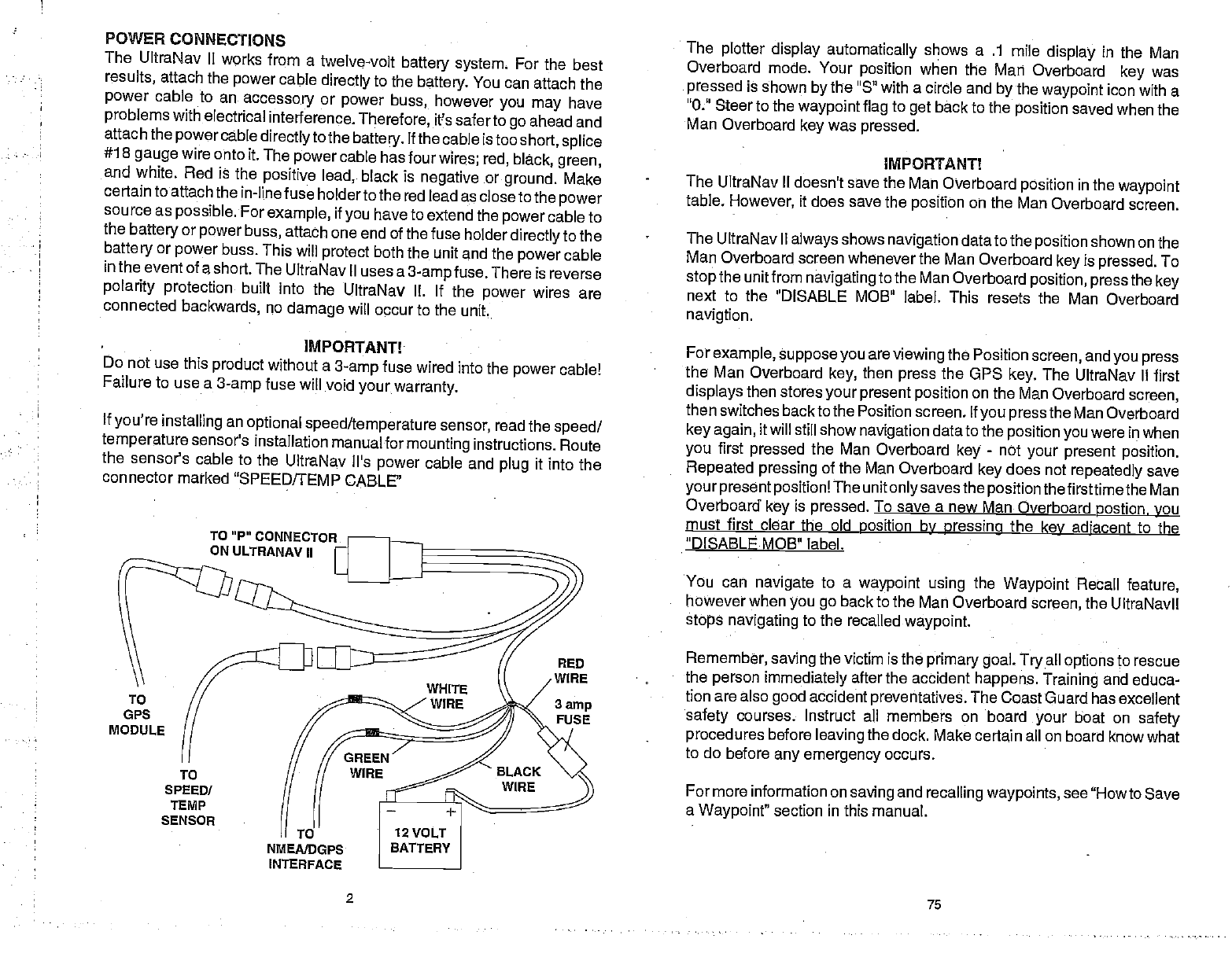
PRESET Thewhitewire isfora NMEA interface. TheUltraNavII sends datato
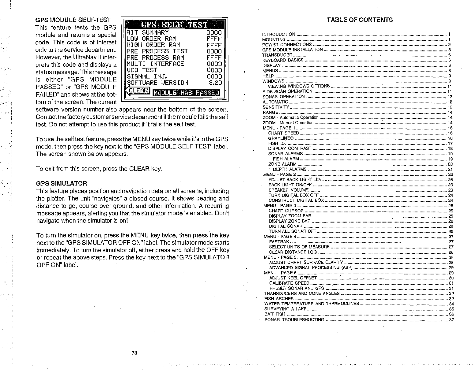
ThePresetfeaturereturnsallsonar andOPSunitstotheir
originalfactory
settings. This resets the units of measure, speaker volume, automatic
modeonthe
sonarside,displaycontrast,andmore.Thisdoesn'terase
any
waypoints orroutes, however.
To preset
the unit, pressthe MENU key until the"PRESET UNIT"
label
appears.Pressthe
key
nexttothatlabel.Themenuscreendisappearsand
theUltraNavIIreturnsto
theOPS
position
screen.Allunitswillbereturned
totheir
factorysettings.
MAN OVERBOARD
Oneofboating'smostterrifying eventsishavingafriend
orfamily
member
falloverboard.Thissituationcanbedeadlyonanybodyofwater,
freshor
salt. It'sparticularly dangerousatnightorif you're
outofsightofland. Of
course, the firstthingto do is remain calmandtry all standard safety
measurestotry
and rescuethe
person.If
youlosesight
ofthe
person,you
canusetheUltraNav II tohelp startasearchpattern.
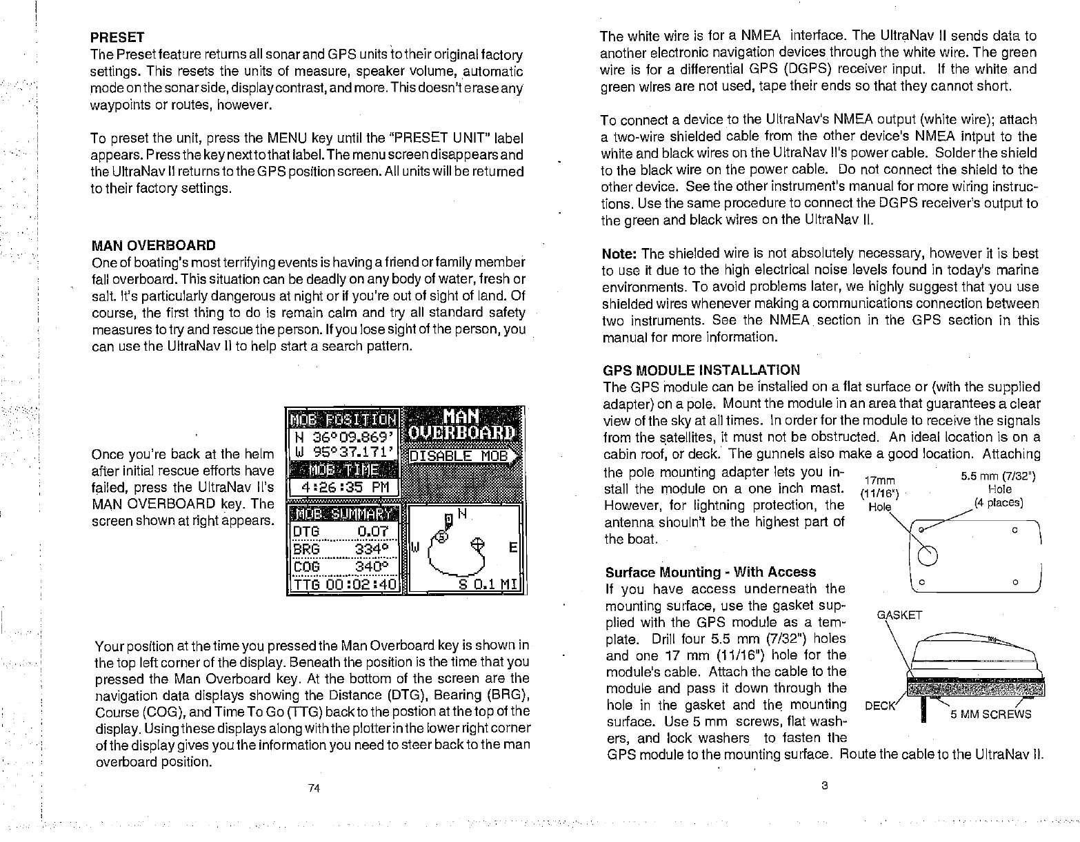
Once
you're backatthehelm
afterinitial rescue efforts have
failed, press the UltraNav Vs
MAN OVERBOARD key. The
screenshownatrightappears.
iasmffg
H 36°09.669'
UI 9E°37.171'fIsnBLEMOBS
isiia[
4:26:35 Pfl
..L
DTI3 0.07 FHJ
BRG 3340
bbs 3400 [H]
E
TTG00:O2:4O . S0.11I
Yourpositionatthetime
youpressed
theManOverboardkeyisshown in
the
topleftcornerofthedisplay. Beneaththepositionisthetimethatyou
pressed theMan Overboard key. Atthe bottom of the screen arethe
navigation data displays showing the Distance (DTG), Bearing (BRG),
Course(COG),andTimeToGo(TTG)backtothe
postionatthe
top
ofthe
display.Using
these
displaysalong
withthe
plotterinthe
lower
right
corner
ofthe
displaygivesyou
theinformationyou
needtosteerbacktotheman
overboardposition.
anotherelectronic navigation devices through
thewhitewire.Thegreen
wire isforadifferential GPS (DGPS) receiver input. Ifthe white and
green wires are notused, tape theirends sothattheycannotshort.
Toconnect adevice totheUltraNav's NMEA output(white wire); attach
atwo-wire shielded cablefromtheotherdevice's NMEA intputto the
whiteandblackwiresontheUltraNav il'spower
cable. Soldertheshield
tothe black wire on thepower cable. Do notconnecttheshield tothe
otherdevice. Seetheotherinstrument's manualformore
wiring instruc-
tions.UsethesameproceduretoconnecttheDGPS receivers
output
to
thegreen and blackwiresontheUltraNav II.
Note:Theshielded wire isnotabsolutelynecessary, howeveritisbest
to useitduetothehighelectrical noiselevels found in today'smarine
environments. Toavoid
problems later, wehighly suggest
that
youuse
shieldedwireswhenever making acommunications connection between
two instruments. See the NMEA sectionin the GPS section in this
manual formore information.
GPS MODULE INSTALLATION
TheGPS thodule canbeinstalled onaflat surface or(with
the supplied
adapter)onapole. Mountthemodule inanareathatguarantees aclear
viewofthesky
atall times. Inorderforthemoduletoreceivethe
signals
fromthesatellites, it must notbeobstructed. An ideallocation ison a
cabin
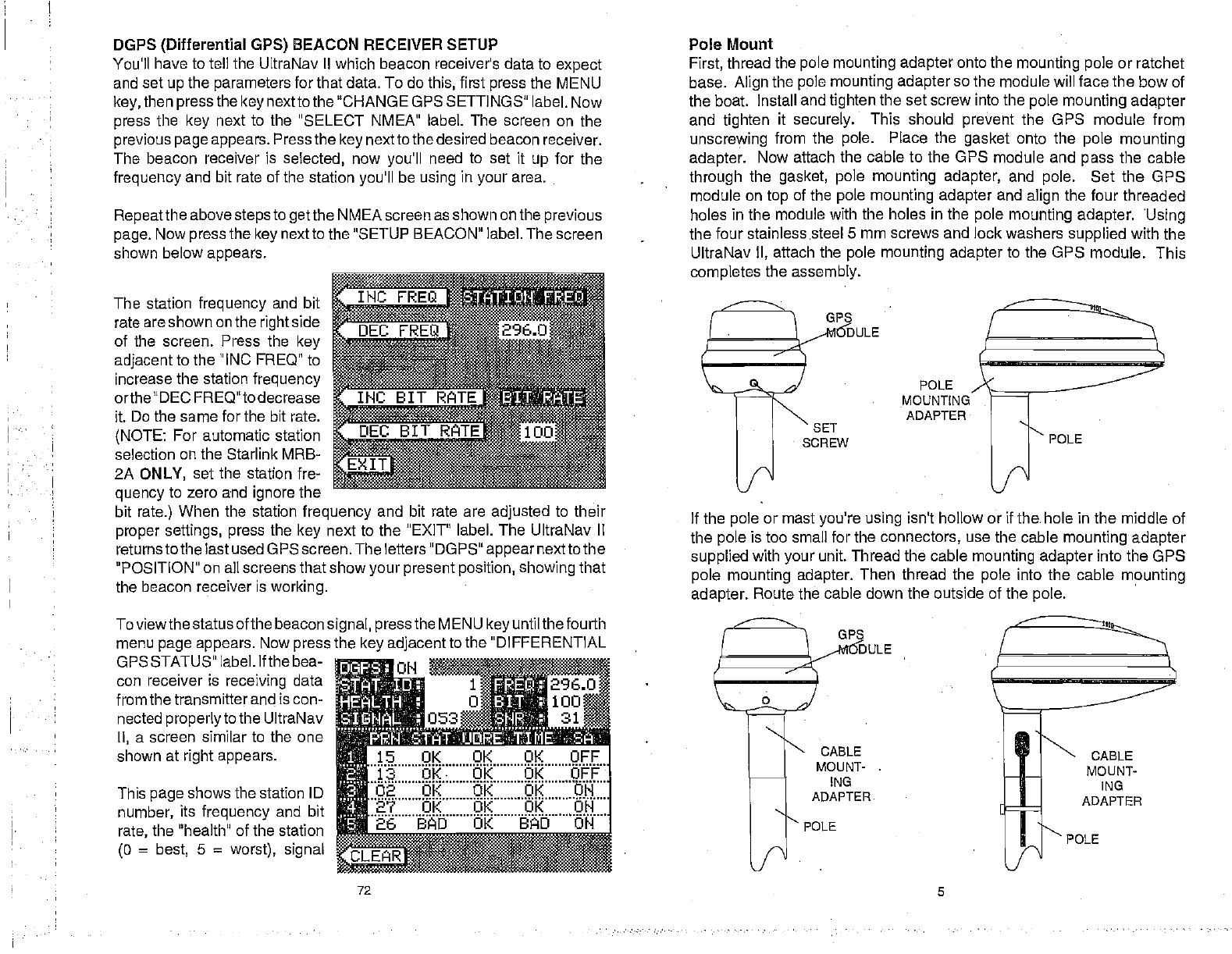
roof,ordeck. Thegunnels also make agood location. Attaching
the polemounting adapter
lets youin-
stall themodule on a one inch mast.
However, for lightning protection, the
antenna shouln't be the highest partof
theboat.
SurfaceMounting-WithAccess
If you have access underneath the
mounting surface, usethegasket sup-
plied with the GPS module as a tem-
plate. Drillfour 5.5 mm (7/32a) holes
and one 17 mm (11/16") holefor the
module's cable. Attach thecabletothe
module and pass it downthroughthe
hole in
surface.
ers, and
GASKET
/
DECK .
sMMscREws
GPSmoduletothe
mounting surface. RoutethecabletotheUltraNavII.
17mm
(11/16')
Hole
5.5mm (7/32")
Hole
(4places)
the gasket and th mounting
Use5mm screws, flatwash-
lock washers to fasten the
74 3
PDF compression, OCR, web-optimization with CVISION's PdfCompressor