Eaglemoss T-34-85 User manual

STEP 25
The cover was locked by means of two latches attached
inner side. A self-locking handle was tted to the central
section of the cover, whose housing was welded
to the inner side.
The cover had two vertical windows for the prismatic
observation devices for the driver. The prisms were
protected on the outside from bullets and shrapnel by two
folding armoured covers that resembled eyelids.
The base for the devices was tted in the upper
section of the hatch. Seals tted into grooves welded
to the inside rim, plus plates welded to the external
cover, were supposed to prevent gun shot entering
the tank.
From 1942, a hatch of a simplied shape with two
prismatic observation devices was introduced, while
the hatch’s thickness was increased from 45 to 75 mm.
ASSEMBLY GUIDE
THE T-34-85 IN DETAIL
T-34 tanks produced between 1940-1941 were fitted with a heavy, hinged driver’s
hatch which had two bases for prismatic observation devices, or triplexes, in which
a glass prism was fitted in the periscope.
The hatch had two
windows for the prismatic
observation devices,
protected from
the outside by hinged
armoured covers
(seen here closed).
1

ASSEMBLY GUIDEASSEMBLY GUIDE
3
025G
025C
025B
025K
025D
025J
025G 025G
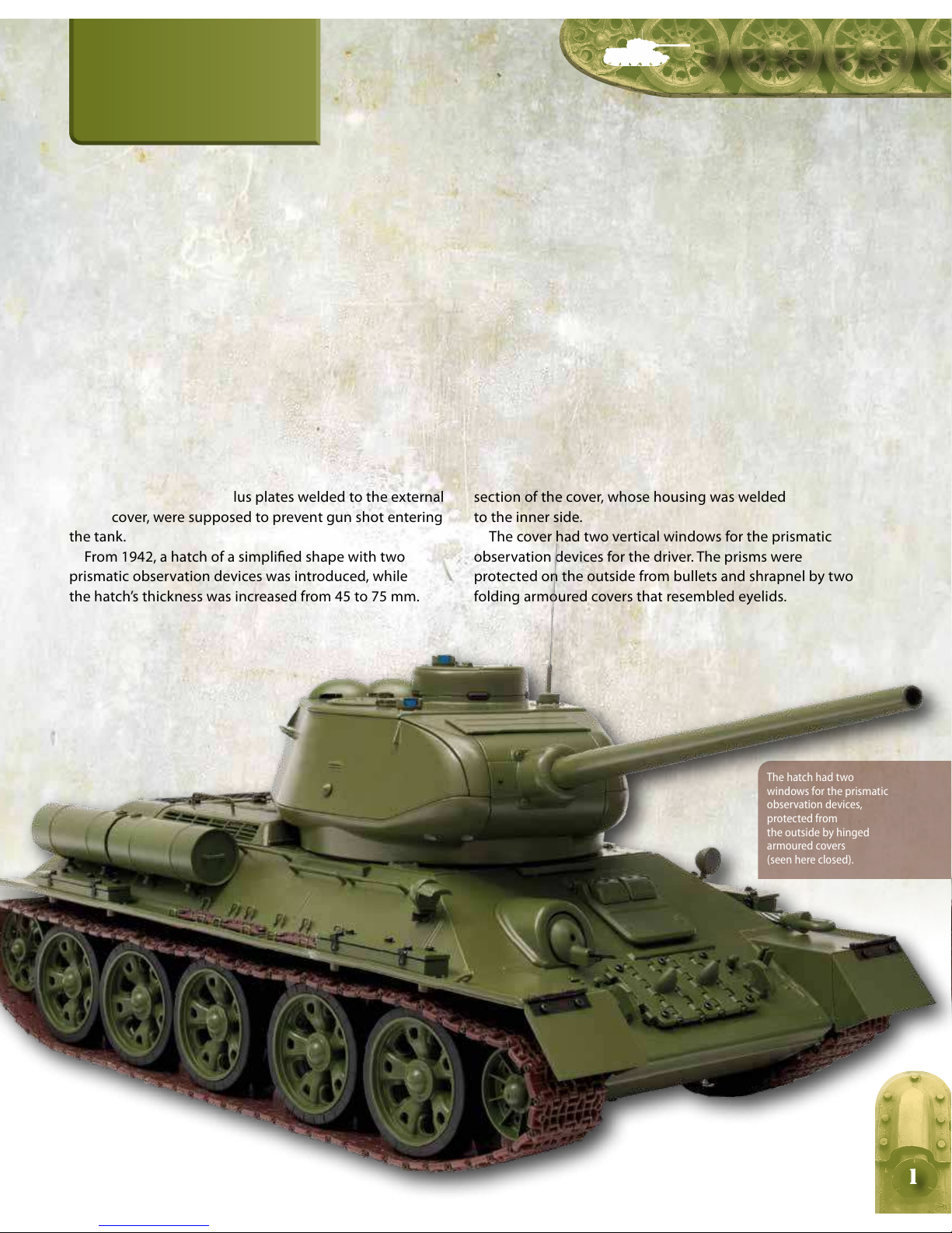
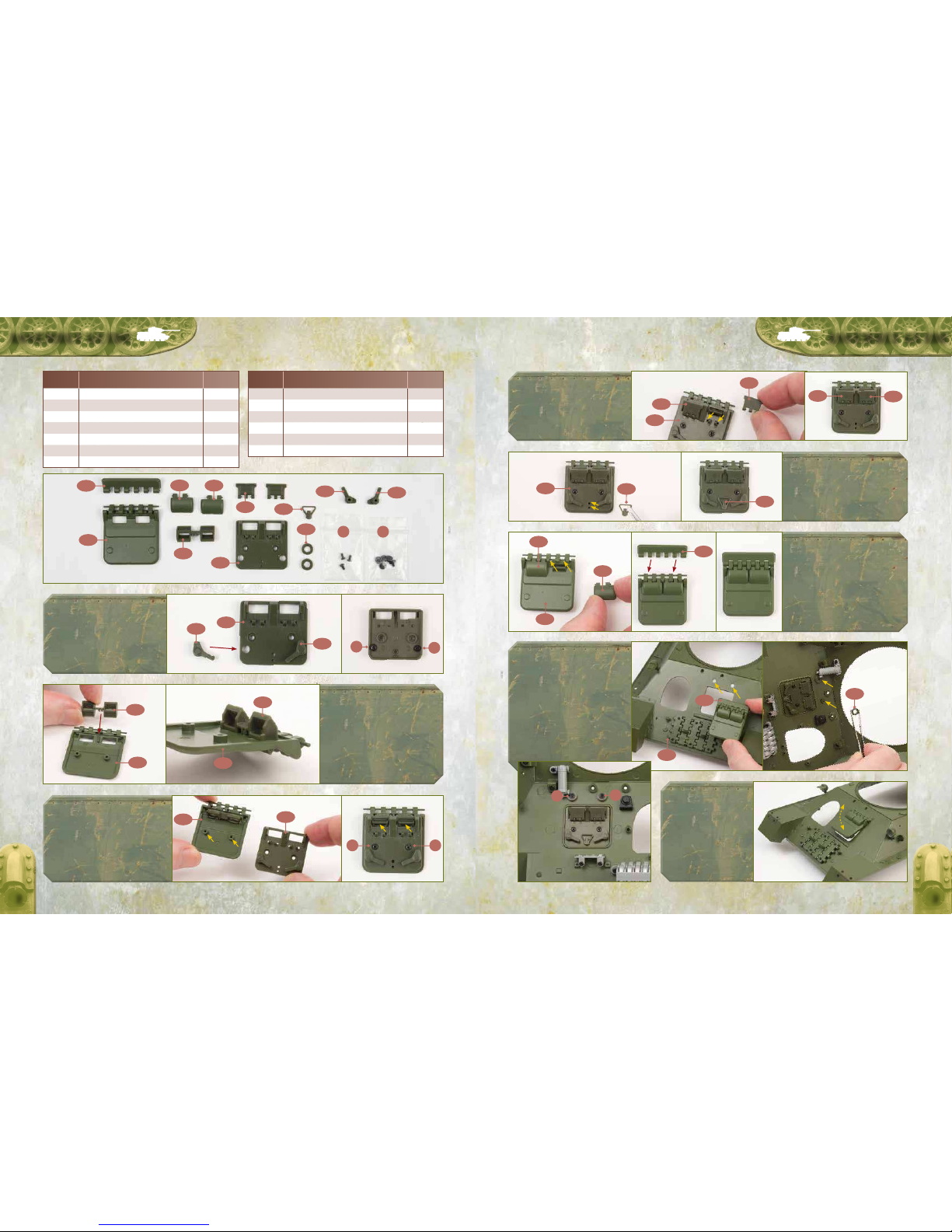
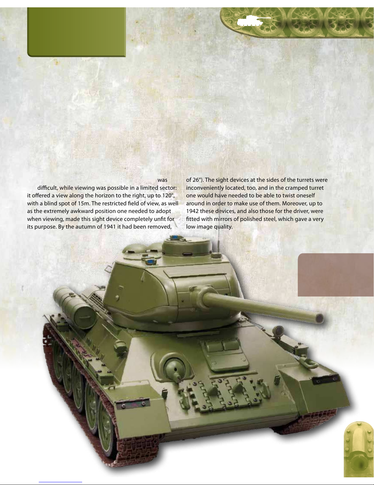
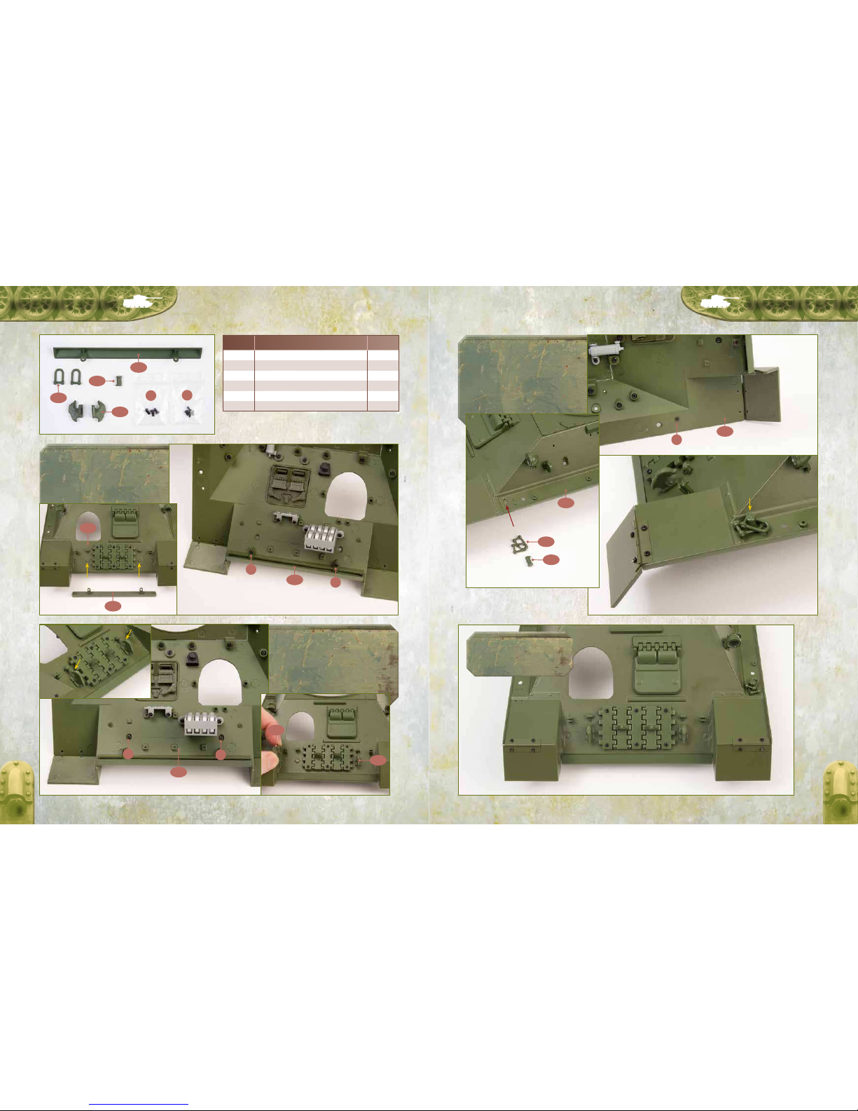
4Clip the hinge pins of the two
persicope inner covers (025G)
firmly into the hinge bases on
the driver’s hatch inner face (025F).
6Clip the hinge pins of the left
periscope cover (025C) into
the hinge base on the driver’s
hatch (025A) so that it covers the
left periscope. Repeat for the right
periscope cover (025D). Then clip the
driver’s hatch hinge (025B) over the
other side of the hinge base.
7Fit the driver’s hatch assembly
over the central aperture in the
front of the upper hull (012A)
and engage the two screw posts in
the underside of the hinge (025B)
with the holes above the aperture.
Turn the upper hull upside-down
and place the two spacers (washers)
(025K) over the protruding screw
posts, then fix with two HP screws.
8This is how the
driver’s hatch looks
when it is fitted.
NOTE: With the lock
handles (025H and 025I)
unfastened on the inside,
the hatch can be lifted up
and down.
5Push the driver’s hatch closing
handle (025J) into the two
holes in the driver’s hatch
inner face (025F) in the position
shown.
HP HP
025F
025F
025A
012A
025G
025J
025B
025C
025K
025D
025E
025H
025F
025E
025A
025G
1Fit the driver’s hatch left hook
handle (025H) and right hook
handle (025I) to the driver’s
hatch inner face (025F) in the
positions shown. Fix each handle
from behind with an HP screw.
3Fit the driver’s hatch inner face
(025F) over the driver’s hatch
(025A), ensuring that the screw
posts engage with each other inside
and that the persicopes protrude
through the two rectangular apertures.
Fix with two BP screws.
2Push the driver’s periscopes
(025E) into the two rectangular
apertures in the driver’s hatch
(025A). Ensure that the two ridges
between the periscopes fit over the
single off-set ridge between the two
holes – the persicopes will therefore
only fit correctly one way round.
BP HP
HP
BP
HP
BP
CODE
NUMBER COMPONENT NAME QUANTITY
025A Driver’s hatch 1
025B Driver’s hatch hinge 1
025C Left periscope cover 1
025D Right periscope cover 1
025E Driver’s periscopes 1
025F Driver’s hatch inner face 1
025G Persicope inner cover 2 * includes spares
025B
025A
025F
025F
025A
025H
025J
025I
025I
025E
025A
CODE
NUMBER COMPONENT NAME QUANTITY
025H Driver’s hatch left lock handle 1
025I Driver’s hatch right lock handle 1
025J Driver’s hatch closing handle 1
025K Spacer (washer) 2
BP 1.7 × 4mm screw 2+1*
HP 1.7 × 3 × 5mm screw 4+1*
2

STEP 26
The T-34-85 tank was
equipped with three MK-4
periscopic rotating sights.
The gunner’s sight and
the loader’s sight were
located in the turret roof,
while the commander’s sight
was placed in the hatch
cover of the commander’s
cupola.
It was not the thickening of the turret’s armour plating
that made the T-34-85 more formidable, but the
installation in it of a powerful new gun. With a 76-mm
gun, the ring distance could be increased, with
a corresponding decrease in the probability of the tank
being struck by enemy shells. Of major importance
was the provision in the turret of space for a third crew
member, which relieved the commander of the need
to function as the gunner, enabling him to concentrate
ASSEMBLY GUIDE
THE T-34-85 IN DETAIL
It was in enhancing the means of attack, not defense, that improved
the performance of the T-34-85.
1
fully on observing the battleeld, searching for targets
and most importantly, leading the his crew members with
maximum eectiveness. As a result, ecient pre-emptive
and retaliatory re and the eectiveness of anti-artillery
manoeuvres were considerably enhanced. Improved sights
and a radio set also helped. The presence, in particular,
of a radio allowed not only quick responses to command
orders, but also enabled the commander to be notied
of changes in the situation on the battleeld.

ASSEMBLY GUIDEASSEMBLY GUIDE
2 3
026B
026B
012A
026C
026D
012A
012A
017C
026C
026D
026C
026D
3Fit the hull front reinforcement
(026B) into the two recessed holes
on the front of the upper hull
(012A) beside the turret ring base. Fix from
beneath the upper hull with two BP screws.
4Push one of the hull U-forks (026C)
firmly into the small hole in the left
front of the upper hull (012A). There
is a lug on the lower side of the engaging
pin to ensure the U-fork fits the correct way
up. Repeat for the second hull U-fork (026C)
on the right front of the upper hull.
5Push the two hull opening forks
(026D) into the two small holes in
the left side of the upper hull (012A),
centrally beneath the left radiator air intake
grille (017C). Orientate the hooks as shown.
BP BP
026B
026C
026D
012A
026A
026A
026A
026A
026A
1Fit one of the hull side reinforcements
(026A) into the two recessed holes
on the left side of the upper hull
(012A) beside the turret ring base. Fix from
beneath the upper hull with two BP screws.
2Fit the second hull side reinforcement
(026A) into the two recessed holes on
the right side of the upper hull (012A)
beside the turret ring base. Fix from beneath
the upper hull with two BP screws.
BP
BP
BP
BP
BP
CODE
NUMBER COMPONENT NAME QUANTITY
026A Hull side reinforcement 2
026B Hull front reinforcement 1
026C Hull U-fork 2
026D Hull opening hook 2
BP 1.7 × 4mm screw 6 + 2*
* includes spares

and only the PT-4-7 sight could be used for 360° viewing
(which allowed viewing only within a very narrow sector
of 26°). The sight devices at the sides of the turrets were
inconveniently located, too, and in the cramped turret
one would have needed to be able to twist oneself
around in order to make use of them. Moreover, up to
1942 these devices, and also those for the driver, were
tted with mirrors of polished steel, which gave a very
low image quality.
In 1940, the 360° sight device was installed to the rear
of the tank commander’s position in the turret hatch
cover on the right. Looking through the device was
dicult, while viewing was possible in a limited sector:
it oered a view along the horizon to the right, up to 120°,
with a blind spot of 15m. The restricted eld of view, as well
as the extremely awkward position one needed to adopt
when viewing, made this sight device completely unt for
its purpose. By the autumn of 1941 it had been removed,
STEP 27
ASSEMBLY GUIDE
THE T-34-85 IN DETAIL
The poor quality and location of the T-34’s sight devices was considered a major
shortcoming as early as 1940; by 1941 improvements were under way.
1
In 1942 SLR sight devices
in the T-34 were replaced
by prismatic ones, while
in the «improved» turret
there were already vision
slits with triplex glass
blocks.

ASSEMBLY GUIDEASSEMBLY GUIDE
2 3
027A
027B
027C
027B
027C
027B
027A
1Fit the cradle (027C) to the lower half
of the external fuel tank 1 (027B),
ensuring that the two screw posts fit
into the recesses in the lower horizontal
channel. Fix from inside with two BP screws.
2Fit the upper half of the external fuel
tank 1 (027A) over the lower half
(027B), ensuring that the filler cap is
at the top, closest to the cradle handle. Fix
with two BP screws through the back.
BP
BP
BP
BP BP
CODE
NUMBER COMPONENT NAME QUANTITY
027A External fuel tank 1 upper half 1
027B External fuel tank 1 lower half 1
027C Cradle 1
BP 1.7 × 4mm screw 6 + 2*
* includes spares
012A
012A
3Fit the assembled fuel tank to the
two sockets at the rear left of the
upper hull (012A), ensuring that the
filler cap and handle are at the top. Fix with
two BP screws from inside the upper hull.
BP
BP
4This is how the upper hull
looks when the external
fuel tank 1 has been fitted.

STEP 28
– especially in a moving, shaking tank – was virtually
impossible. For this reason, the driver often opened
his hatch slightly, which enabled him to nd his bearings
by the terrain. In addition, the driver’s sight devices quickly
became clogged with dirt and dust. Armoured covers,
or “eyelids”, slowed the process: while the tank was moving,
one “eyelid” was closed and the driver was able to observe
through the other ; when that became clogged with dirt,
the rst one was opened.
Two mirrored sight devices were located on the T-34’s
front hull plate, while a central mirrored periscope was
tted in the upper section of the hatch cover. Since
the beginning of 1942 the T-34 was tted with a driver’s
hatch of a simpler shape with two prismatic vision devices.
For protection against bullets and shrapnel, the prisms
were closed on the outside with folding armoured covers.
The quality of the prisms, made of yellow-green organic
glass, was dreadful. Trying to see anything through them
ASSEMBLY GUIDE
1
THE T-34-85 IN DETAIL
Until mid-1943, the quantity and quality of sight devices on the T-34 was poor,
which created serious difficulties for all crew members.
Insufficient sight devices,
their poor location and low
quality lead to the loss
of visual contact among
the tanks and premature
detection by the enemy.

ASSEMBLY GUIDEASSEMBLY GUIDE
2 3
028D
028C
028B
028A
028A
012A
028A
012A
028D
028D
1Fit the hull nose piece (028A) to the
front of the upper hull (012A) and fix
with two HM screws through the two
tabs into the posts on the underside of
the hull.
2Fit the opening hooks (028D) to
the raised fixing holes at the front of
the upper hull (012A), ensuring that
the notch engages and that the larger part
of the hook it uppermost. Fix each hook
with an IP screw from beneath the hull.
HM IP
HM
IP IP
HM
CODE
NUMBER COMPONENT NAME QUANTITY
028A Hull nose piece 1
028B Towing hook 2
028C Peg 1
028D Opening hook 2
HM 2.0 × 4mm screw 2 + 1*
IP 1.7 × 3mm screw 3 + 1*
* includes spares
012A
012A
028B
028C
3Fit the peg (028C) through the
loops of both towing hooks (028B).
Then fit the base of the peg into
the socket behind the front left mudguard
in the upper hull (012A), ensuring that the
notch engages. Fix with an IP screw from
beneath the hull.
IP
4This is how the front of the
upper hull looks when this
stage is complete.
Table of contents
Popular Toy manuals by other brands

V-tech
V-tech Jake And The Neverland Pirates Smart Ship Learn &... user manual

V-tech
V-tech Switch & Go Dinos - Quiver the Stygimoloch user manual

Modeltech
Modeltech P-47 Thunderbolt Instructions for final assembly

V-tech
V-tech Smart Friends Bowling user manual

Lightmybricks
Lightmybricks LEGO Winter Village Bakery 10216 Lighting... manual

Lightmybricks
Lightmybricks 76178 installation guide

V-tech
V-tech Soothe & Surprise Nature Light user manual

V-tech
V-tech V.Smile Jammin Gym Class user manual

V-tech
V-tech Gini Product information guide

Hobby King
Hobby King Katana EPP-30E instruction manual

V-tech
V-tech ABC Choo Choo user manual

Spinmaster
Spinmaster AIRHOGS ZERO GRAVITY LASER Instruction guide