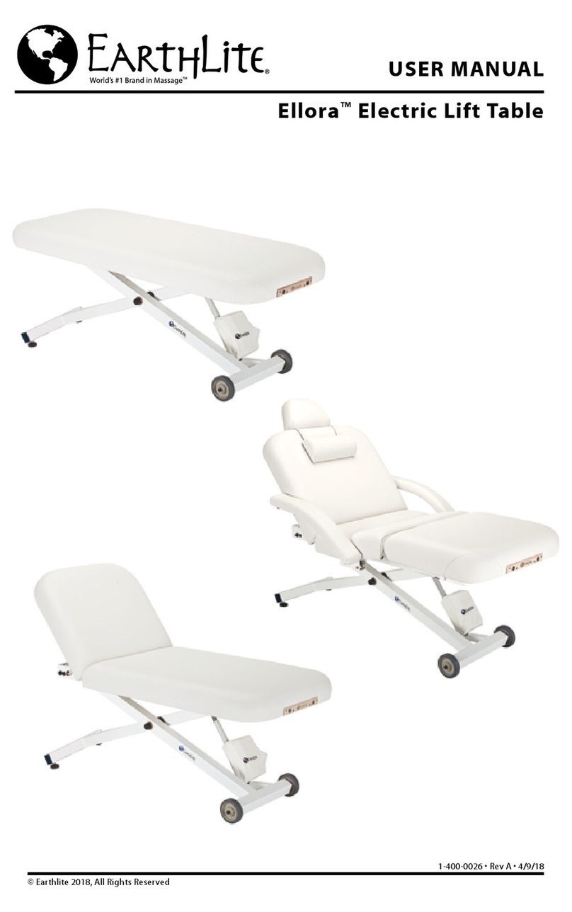
Earthlite Ellora Vista Salon User manual

USER MANUAL
Ellora Vista™Electric Lift Table
1-400-0027 • Rev C • 4/30/2019
© Earthlite 2019, All Rights Reserved
Salon
Tilt
Flat

© Copyright 2019
Earthlite®
All rights reserved. This document
or any portion thereof may not be
reproduced in any way, including
photocopying or translation to
another language without the prior
written permission from Earthlite®.
Earthlite®is a registered trademark of
Earthlite, LLC.
Legal Notice
The information provided in this document is intended
for informational purposes only and is subject to change
without notice. The information provided in this document
should not be construed as a commitment by Earthlite®.
Earthlite®assumes no responsibility for the accuracy or
suitability of the information contained in this document.
This document may contain technical inaccuracies or
errors. Earthlite®makes no expressed or implied warranties
of any kind concerning the information contained in
this document, including, but not limited to, the implied
warranties of merchantability and tness for purpose.
Earthlite®shall not be liable for incidental or consequential
damages in connection with or arising out of the product,
performance, or use of this document and the information
and material it describes.

Congratulations on your purchase! Earthlite’s Ellora Vista™ is perfect for day spas, medi-spas,
and resorts. It features a whisper-quiet yet powerful electric lift actuator complete with on-
demand height adjustments. This stunningly designed table provides exceptional comfort,
function, and years of trouble-free use.
INTRODUCTION
TABLE OF CONTENTS
SAFETY INFORMATION
Safety Symbols
Warnings
Product Overview
Table Specicaons
Secon 3: Installaon
Table Removal from Shipping Crate
Leveling Instrucons
Placement and Installaon
Secon 4: Operang Instrucons
Foot Control Operaon
Pneumac Back Tilt Informaon
Pneumac Leg Break Informaon
Hand Control Operaon
Table Reset
Weight & Li Capacies
Replacing a Foot Glide Leveler
Electrical Specicaons
Accessory Opons
Secon 5: Care & Maintenance
Troubleshoong
Care & Maintenance
Warranty Informaon
Contact Us
2
2-3
4
5
6
6
7
8
9
10
11
12
12
13
13
14
14
15
back cover

1) Always unplug this furnishing from the electrical outlet before servicing.
2) Never use this furnishing if it has a damaged cord or plug, if it is not working properly, if it has been
dropped or damaged, or dropped into water. Return the furnishing to a service center for examination
and repair.
3) Keep the cord away from heated surfaces.
4) Do not use outdoors.
5) Do not operate where aerosol (spray) projects are being used or where oxygen is being administered.
6) To disconnect, turn all controls to the off position, then remove plug from outlet.
7) Connect this furnishing to a properly grounded outlet only. See Grounding Instructions.
READ AND SAVE THESE INSTRUCTIONS
INTERNATIONAL VERSIONS ONLY
This product is for use on a nominal 220V-240V circuit and has a
grounding plug (plug type varies by country). Make sure that the
product is connected to an outlet having the same conguration as
the plug. No adapter should be used with this product.
NORTH AMERICA ONLY
Grounded
Outlet Box
Grounded Outlet
Grounding Pin
GROUNDING INSTRUCTIONS:
POWER SUPPLY: (120V AC grounded) Electrical limitations: Do not use extension cord with this product, plug
directly into grounded outlet. This product must be grounded. If it should malfunction or breakdown, grounding
provides a path of least resistance for electric current to reduce the risk of electric shock. This product is equipped
with a cord having an equipment-grounding conductor and a grounding plug. This three prong grounded plug
will only t into wall outlet one way. If the plug does not t fully in the outlet, contact a qualied electrician to
install the proper outlet. Do not change the plug in any way.
2
SAFETY INFORMATION
Safety Symbols
Familiarize yourself with the following
Safety & Warning symbols. They are
designed to prevent damage and injury to
you, your clients, and your new Earthlite
product.
IMPORTANT: The important safety
instructions and warnings in this manual
cannot cover all possible problems and
conditions that can occur. Use common
sense and caution when installing,
operating, or maintaining this appliance.
Indicates an imminently hazardous
situation which could result in serious
or fatal injury.
Indicates a potentially hazardous
situation which could result in serious
injury.
Indicates a potentially hazardous
situation which could result in
equipment damage and/or injury.
RISK OF ELECTRIC SHOCK, FIRE, AND EXPLOSION

3
2) When lowering the table height, be sure there are no foreign obstacles are underneath your table
that could obstruct it from lowering completely. This could damage your table.
3) Never set anything under the table frame to avoid collision if lowered.
4) Never operate your table on an uneven surface. Adjust the leveling feet so that your table is stable.
5) Never raise the head or leg section with a client in the prone position (face down.)
6) Never use or store your table in a wet or very humid environment. Water and excessive moisture
can damage the wood cabinet and electrical components. Evidence of exposure to water or
moisture will void your warranty.
7) If you have purchased the Flexible Armrest Option, never use the Armrests as handholds or body
support mechanisms, especially when setting clients on or off the table.
8) Never drop or insert any object into any opening.
SAFETY INFORMATION
1) Use this furnishing only for its intended use as described in these instructions. Do not use
attachments not recommended by the manufacturer.
2) Do not operate this equipment unless properly trained.
3) Install this furnishing in treatment area not accessible to the public.
4) Close supervision is necessary when this furnishing is used by, or near children, invalids, or disabled
persons.
5) This product does not have “pinch point” protection. Only operate when no possibility of any portion
of the body could be caught and injured while moving the table top upward/downward, or activating
the back/foot tilt.
6) Do not use this furnishing to support video equipment such as televisions or computer monitors.
7) Never attempt to use the Head or Leg lift section to support concentrated weight such as sitting
or standing
READ AND SAVE THESE INSTRUCTIONS
To reduce the risk of burns, re, electric shock, or injury to persons:
1) When lowering any section of the table, make sure that no supplies or any
part of yours or your client’s body is between the top of your table and its base.
This could result in injury, or could damage your table as well as the item. It is
recommended that you always return your table top to the lowest at position to
avoid leaving the base exposed.

4
The Ellora Vista™is constructed with state of the art materials beginning with a heavy-duty curved
steel frame. The upholstered tops are available in three (3) separate variations, Salon, Tilt, and Flat. The
Ellora Vista™was designed with operational simplicity in mind. The height adjustment functionality is
controlled by a single foot control. The Salon and Tilt variations of the table are equipped with pneumatic
and manual back tilts and leg breaks. There are different mechanisms used on pneumatic assists and
manual assists. There is no assembly required for your Ellora Vista™.
The following information lists features, specications, and options for your stationary massage table:
FEATURES
• Heavy Duty Curved Steel Frame
• Reliable Motor
• Luxuriously Upholstered Top
• Pro-Plush™Deluxe 3-Layer 3”
Cushioning System
• Hands Free Foot Control
• Natursoft™Upholstery – 100% PU
in 14 colors
• ADA Compliant
• Lifetime Limited Warranty on Frame
3 yrs on foam and upholstery
2 yrs on motor and controls
SPECIFICATIONS
• Widths: 28”, 30”, 32”
• Length: 73”
• Height Range: 18” – 36”
• Lift Capacity: 650 lbs.
OPTIONS
• Non-Electric Pneumatic-Assist
(Tilt or Salon Top)
• Extra Foot Pedal
• UltraLeather™Upholstery
• Flex Arms, Neck Roll and Head Pillow
(Salon Top Only)
• Flex-Rest™or Caress™Facecradle
• 4” Memory Foam System
• Face Hole (Non-Tilt End Only)
• Deluxe Adjustable Armrests
(Non-Tilt End Only)
TABLE SPECIFICATIONS
5”
18”
73”
36”
23.5”
18”
11.5” 10” 28”
21.25”
21.25”
21.25”
73”
28”
30”
32”
73”
28”
30”
32”
73”
28”
30”
32”
36”
75º electric
23.5”
5”
18”
28”
73”
73”
36”
Flat
60º pneumatic
Overhead
Prole
Overhead
Prole
Overhead
Prole
Prole
Prole
Prole
60º pneumatic
75º electric
Salon
Tilt

5
A
B
C
D
The following steps will guide you through carefully removing your Ellora™ Vista Stationary table from
the shipping crate. We recommend wearing work gloves during these steps.
Remove the rectangular cardboard lid from the top of the table. Once you have removed the cardboard
lid and surrounding cardboard walls from shipping crate, you will nd the wheels and foot glide
levelers are seated tightly within wood brackets which have been screwed into the plywood base of
the shipping crate.
UNPACKING YOUR ELLORA VISTA™ STATIONARY TABLE
RECOMMENDED TOOLS NEEDED
TABLE REMOVAL FROM SHIPPING CRATE
Phillips #1 Screw
Driver
Step 1
With a Phillips #1 screwdriver (or a powered screwdriver),
carefully unscrew and remove the two (2) Front facing
wood brackets from the plywood base.
(Diagram A)
We recommend removing the two (2) front facing wood
brackets (Diagram A) that enclose the foot glide levelers.
Do not remove the rear brackets which enclose the rear
wheels (Diagram B). These brackets are twice as thick as
the front brackets, and will be more difcult to remove.
Step 2
Once the front brackets are removed, Carefully pull the
Ellora™ Vista straight away from the rear brackets and
slide the table onto the oor. We recommend at least two
(2) people conduct this step together.
(Diagram C)
It is possible to lift the table directly out of the shipping
crate without removing any of the wood brackets, but this
is dangerous and not recommended because the weight of
the table is at least 200 lbs.
Step 3
Once the table is pulled safely away from the shipping
crate, make sure the path from the table to your preferred
destination is clear of any obstacles or tripping hazards.
(Diagram D)
Work
Gloves
If you did not have your table shipped with ‘white glove’ service, you may be
required to remove your table from its shipping crate. We highly recommend that
at least two people conduct the following steps to uncrate the table.

6
LEVELING THE TABLE
Not all commercial and residential oors are perfectly level. The Ellora™has foot glide levelers that
swivel into place against the oor. If your table is not already level when you remove it from the
shipping crate, follow these easy steps to level your table:
Step 1
Locate which foot glide leveler
is not even with the oor.
Step 3
Once the foot glide leveler is tight
with the oor, apply pressure on
top of the table to conrm stability.
Step 2
Rotate the foot glide leveler
clockwise or counter clockwise
to bring it to ground level.
PLACEMENT AND INSTALLATION
Once your table is placed safely on the oor, temporarily plug the table into a power outlet and using the
foot control, raise the table to waist height, which will make it easier for moving. Once the table is at the
desired height, unplug the power cable from the outlet and place the power cable along with the foot
control on top of the table to prevent a tripping hazard. For ease of movement and exibility, your table
was built with two (2) rear wheels and two (2) front foot glide levers.
The following steps will guide you through safely moving your table to the desired location. We
recommend that at least two (2) people conduct the following steps:
Step 1
Locate the front and rear sections of the table frame underneath the upholstered top as designated by
the black arrows above. These are the recommended locations to hold when guiding your table to the
desired location (Diagram A1).
Step 2
Ensure there are no obstacles or tripping hazards in the way and carefully pull the table by the frame
into the desired location (Diagram B). A second person’s assistance is recommended to help push the
table from the opposite end.
Note Regarding Step 1:
Locate the front crossbar of the table frame where the foot glide levelers are located (Diagram
A2). This is a secondary recommended section of the frame to hold if you prefer, but may be more
difcult. If you choose this location, properly bend at your knees prior to lifting or pulling the table.
Do NOT pull or push the table from the upholstered top. Moving the table
in this fashion can damage the table and put too much pressure on hinges
or other components of the table. Damage made to the table by pulling or
pushing on the upholstered top may void the warranty (Diagram C).
Install this furnishing in treatment area not accessible to the public.
SAFETY ZONE: The treatment area must have 3-ft minimum unobstructed
clearance around entire table. Posting a notice is recommended to
maintain “Safety Zone Clearance”. The designated work area around the
table should be clearly marked off.
A1
A2
BC

7
The Ellora Vista™ comes out of the shipping crate ready to go to work. The foot control is already
connected, allowing you to simply raise and lower the table with your feet while your hands remain free
to focus on your clients. The left foot pad is designed to lower the table and the right foot pad is designed
to raise the table. The height adjustment range of the Ellora Vista™ is 18” at its lowest position and 36”
at its highest.
Table Down Table Up
There is no on/off switch on the foot control, so even while the table is not in use, the foot control is
still operable. There is a potential for harm or bodily injury when the foot control is being depressed.
We recommend unplugging the table from the power outlet when not in use.
B
The Ellora Vista™ is not equipped with a safety shut off or crush sensor. The area
directly underneath the Ellora™ Vista (designated by the space inside the dotted
line in Diagram B) must remain clear of all objects during operation.
Keep small children away from the table at all times.
FOOT CONTROL OPERATION

8
Step 1
Locate the pneumatic back tilt
handle, which is located on the
right side under the back tilt.
Step 2
The handle is set to the locking
position.
Step 3
Squeeze / press the handle to
release the pneumatic assist,
which allows you to move the
back tilt up or down.
Step 4
With the handle squeezed /
pressed, move the back tilt to
the desired level and release the
handle. It will lock in place.
PNEUMATIC BACK TILT OPERATION
Salon Top & Tilt Top Tables
Pneumatic Ellora Vista™ tables come equipped with a non-electric pneumatic assist mechanism. The
following steps will guide you through operating the pneumatic back tilt control and adjusting the back
to the desired level:
Do Not sit, or put unnecessary amounts of pressure on the back
section of the table when it is in tilt position on any level (Diagram
A). This can damage or destroy the pneumatic assist mechanism
for the back section of the table and cause harm or bodily injury to persons. The
pneumatic assist mechanism of the table is intended solely to be used when a client is
properly seated or laying on top of the table correctly. Damage caused to the table in
this manner can void the warranty.
A

9
Step 1
Locate the pneumatic leg break con-
trol, which is located under the front
section of the table.
Step 2
The handle is set to the locking
position.
Step 3
Squeeze/press the handle to release
the pneumatic assist, which allows
you to move the back tilt up or down.
Step 4
With the handle squeezed/pressed,
move the back tilt to the desired level
and release the handle. It will lock in
place.
A
PNEUMATIC LEG BREAK OPERATION
Salon Top Table
Ellora™ Vista Salon tables with the PowerAssist™ option come equipped with the same non-electric
pneumatic assist mechanisms as mentioned above. The following steps will guide you through operating
the pneumatic leg break control:
Do Not sit, or put unnecessary amounts of pressure on the leg
section of the table when it is in tilt position on any level (Diagram
A). This can damage or destroy the pneumatic assist mechanism for
the leg section of the table and cause harm or bodily injury to persons. The pneumatic
assist mechanism of the table is intended solely to be used when a client is properly
seated or laying on top of the table correctly. Damage caused to the table in this
manner can void the warranty.

10
HAND CONTROL OPERATION
Electric Salon Top & Tilt Top Tables
Electric Ellora™ Vista tables come equipped with a convenient hand control for adjusting the back
and leg section (if applicable), as well as the table height.. The following steps will guide you through
operating the hand control:
Raise Back Section Lower Back Section
Lower Leg Section
(Salon Only)
Lower Entire Table
Raise Leg Section
(Salon Only)
Raise Entire Table

11
TABLE RESET
Electric Salon Top & Tilt Top Tables
Lower Back Section
Lower Leg Section
(Salon Only)
Lower Entire Table
If your electric Ellora™ Vista table is not working properly, it may need to be reset. The following steps will
guide you through the reset process:
Step 1
Press and hold the two
middle buttons of the second
row simultaneously until you
hear a series of beeps.
(Diagram A)
Keep buttons pressed until
beeping stops.
After the back section and leg section are reset and fully retracted to their at positions (like
diagram below), the table will start working normally.
Step 2
Lower back rest down to
a at position.
(Diagram B)
Keep button pressed until
beeping stops.
Step 3
Lower leg section down to
a at position.
(Diagram C)
Keep button pressed until
beeping stops.

12
650 lbs.
50 lbs.
The Ellora Vista™ is powered by a heavy-duty, whisper quiet lift
actuator to enable easy height adjustment, and positioning. The
recommended lift capacity for the Ellora Vista™ massage table is
500 lbs.
The back rest section of the table, whether pneumatic or electric
has a maximum weight capacity of 50 lbs.
50 lbs.
MAX
WEIGHT & LIFT CAPACITIES
If a foot glide leveler becomes damaged or is need of replacement, carefully follow these next steps.
We recommend that at least two (2) people conduct steps 1 & 5.
BC
Step 1
Unplug the table and carefully
lean the table on its side opposite
the foot glide leveler in need of
replacement (Diagram A).
Step 2
Locate the damaged foot glide
leveler in need of replacing
which is attached to its metal
ball joint (Diagram B).
Step 3
Remove the damaged foot glide
leveler by pulling it directly off the
metal ball joint (Diagram C).
Step 4
Attach the new foot glide leveler
to the metal ball joint and push.
The Foot glide leveler will snap
into place (Diagram D).
Step 5
Carefully return the table
back to its upright position
(Diagram E).
A
REPLACING A FOOT GLIDE LEVELER
We recommend at least two (2)
people lay the table on its side
before conducting step 1 & 5. Lay
a towel or blanket down under the
table, before resting the table on
its side to protect the upholstery.
E
D

ACCESSORY OPTIONS
PLUG DESCRIPTIONS & ELECTRICAL SPECIFICATIONS
AT
The Ellora Vista™ Salon
is retrotted with slots
on each side of the table
specically designed to
provide a xed location for
Flex-Armrests (Diagram A).
All Ellora Vista™ massage
tables come with headrest
outlets at both ends,
specically designed for
providing a xed location
for facecradles and salon
pillows (Diagram B).
A neck roll can also be purchased to provide extra comfort
for your clients (Diagram C).
A Foot Rest will add 10” to the length of your table.
Flex-Armrests
Facecradles & Salon Pillows
Neck Roll
Foot Rest
AA
BB
C
China
220V AC
PLUG DESCRIPTION
120V AC 220V AC 220V AC
NORTH AMERICA UK / MIDDLE EAST EUROPEASIA
13
Spec North America Europe/Asia
Service 120 VAC/60Hz 220 VAC/50Hz
Max Amperage 2.3 Amps 1.4 Amps
Voltage 120VAC 220VAC
Max Consumpon 300 Was 300 Was

14
This helpful troubleshooting guide will provide you with information about how to recognize a problem
with your Ellora Vista™, determine possible causes, and nd a solution. In the event your specic situation
is not covered in this guide, please contact Earthlite so our technical support department can assist you.
Earthlite Customer Service (760) 599-1112, or (800) 872-0560
Helpful Tips
My table is wobbling and
moving from side to side.
Table top won’t rise or lower.
Pneumatic hand lever or nger
lever seems stuck.
Where can I nd my table number? The customer might be looking on
the motor.
The table number is located on the
underside of the table, near the
head section on a white label. It
will read ‘SNT’ followed by a 6 digit
number.
My table is making noise when
going up and down.
The center bolt that connects the
legs together is too tight.
Remove the plastic cap covering the
center bolt and loosen the bolt one
half to one full turn.
My table is making a clicking noise
and it’s not going up or down.
The control box is not relaying the
signal from the foot pedal to the
actuator.
Replace the control box.
The table is not level with the oor.
Cables might be caught or tangled.
Adjust one or both of the foot glide
levers until the table becomes level
with the oor and is stable.
Check to see that all the cables
are free and not caught on any
brackets.
Problem Probable Cause Solution
TROUBLESHOOTING
CARE & MAINTENANCE
Perform the following steps as needed for basic maintenance on your Ellora Vista™ massage table and
optional accessories. Perform the basic maintenance recommendations for upholstery between client
treatments.
Upholstery
Category Recommendation Application
Steel
Table Frame
Electronic
Components
Lubrication
& Mechanical
Remove day-to-day dirt with a mild soap and warm water solution. For
tough stains and to disinfect, use a 15:1 water to bleach solution. Always
rinse surface with clean water, and then gently wipe the upholstery. Allow
upholstery to air dry before using or storing. Do NOT use Armor All® or citrus-
based cleansers. For best results, use only the products suggested above.
Alternative cleansing methods may cause serious damage to your table.
Such damage would not be covered under the Earthlite warranty program.
The powder coated steel frame can be kept clean with a mild detergent and
warm water mix. Periodically remove dust from frame with a dry, soft cloth.
Anti-static electronic aerosol dusters can be used to keep the
surfaces of electronic components, power cables, and plugs free
of dust.
If necessary, lubricate wheel joints, casters, foot glide levelers, ball joints, and
other mechanical parts with a light machine oil. Periodically check table and
ensure all bolts remain tightened.
• Table Bed Surface
• Flex-Armrests
• Headrest Cushion
• Salon Pillow
• Bolsters
• Main Steel Frame
and Legs
• Foot Controls
• Hand Controls
• Motors
• Power Cables
• Plugs
• Wheel Joints
• Casters
• Foot Glide Levelers
• Ball Joints, etc.
My table is not going up or
down and it’s not making any
sound.
The foot pedal is not relaying signal
to the control box. Replace the foot pedal.

15
LIMITED LIFETIME WARRANTY
Absolute Satisfaction Return Policy
If you are not completely sased with your Earthlite portable table, chair, or accessory, you
may return it within thirty (30) days for a full refund (excluding shipping & handling charges on
the original order). Standard staonary and li tables may be returned within thirty (30) days
for a refund (excluding shipping & handling charges on the original order) less a 20% restocking
fee. Custom or upgraded products are non-returnable and non-refundable. Proof of purchase
is required to obtain RMA (Return Material Authorizaon) and all returns must be in like-new
condion and in the original packaging. Customers will be responsible for all shipping charges.
Warranty Information
Earthlite oers an industry best warranty against defects in materials, design, and workmanship,
to the original owner, as follows:
• Frame - lifeme warranty
• Foam and upholstery covering - warranted for three (3) years
• Li motors, controls, electronics - warranted for two (2) years from the original date of
purchase*
• Accessories and opons - warranted for one (1) year from the original date of purchase
This warranty does not cover damage caused by normal wear and tear, misuse, accidents, or
neglect, which includes tears in the upholstery and damage caused by cleaners. All warranes
are limited to repair or replacement at Earthlite’s discreon, shipping not included. Proof of
purchase is required to obtain RMA (Return Material Authorizaon) and customers may be
required to return defecve items. Internaonal customers are responsible for all associated
return costs (inbound and outbound), as well as any applicable dues and taxes.
*If within these two (2) years, there is a defect, malfuncon, or failure of the li motor or con-
trols, Earthlite will replace or repair the defecve component at our discreon; shipping not
included. Parts are warranted for 90 days aer replacement or 2 years from the original date of
table purchase, whichever comes later.

Name:
Purchase Date:
Model No:
Serial No:
OWNER’S RECORD

NOTES

Contact Us
Earthlite
990 Joshua Way
Vista, CA. 92081
(800) 872-0560
(760) 599-1112 Int’l
(866) 599-7374 fax
Hours of operation:
Monday - Friday
8:00 a.m. to 5 p.m. PST
Saturday - Sunday
Closed
Visit us online at: earthlite.com
Join us on
Facebook
Follow us on
Twitter
Connect with us
on Linked In
This manual suits for next models
2
Table of contents
Other Earthlite Indoor Furnishing manuals
Popular Indoor Furnishing manuals by other brands

Kimball Office
Kimball Office KORE Assembly instructions

VITRA
VITRA Colonial Table Instructions for use

Artesano
Artesano 24801 Assembling instructions

Core Products
Core Products Boston BT215 Assembly instructions

Living Spaces
Living Spaces 243554 Assembly instructions

KI
KI Uniframe Conver Assembly instructions

Furniture of America
Furniture of America CM-BK608T Assembly instructions

Emmezeta
Emmezeta TDHT132 Assembling Instruction

Whittier Wood
Whittier Wood 1122GACb Assembly instructions

OFM
OFM 130 Assembly instructions

Whittier Wood Furniture
Whittier Wood Furniture 1554AEGAC Assembly instructions

Winsome
Winsome 84084 quick start guide