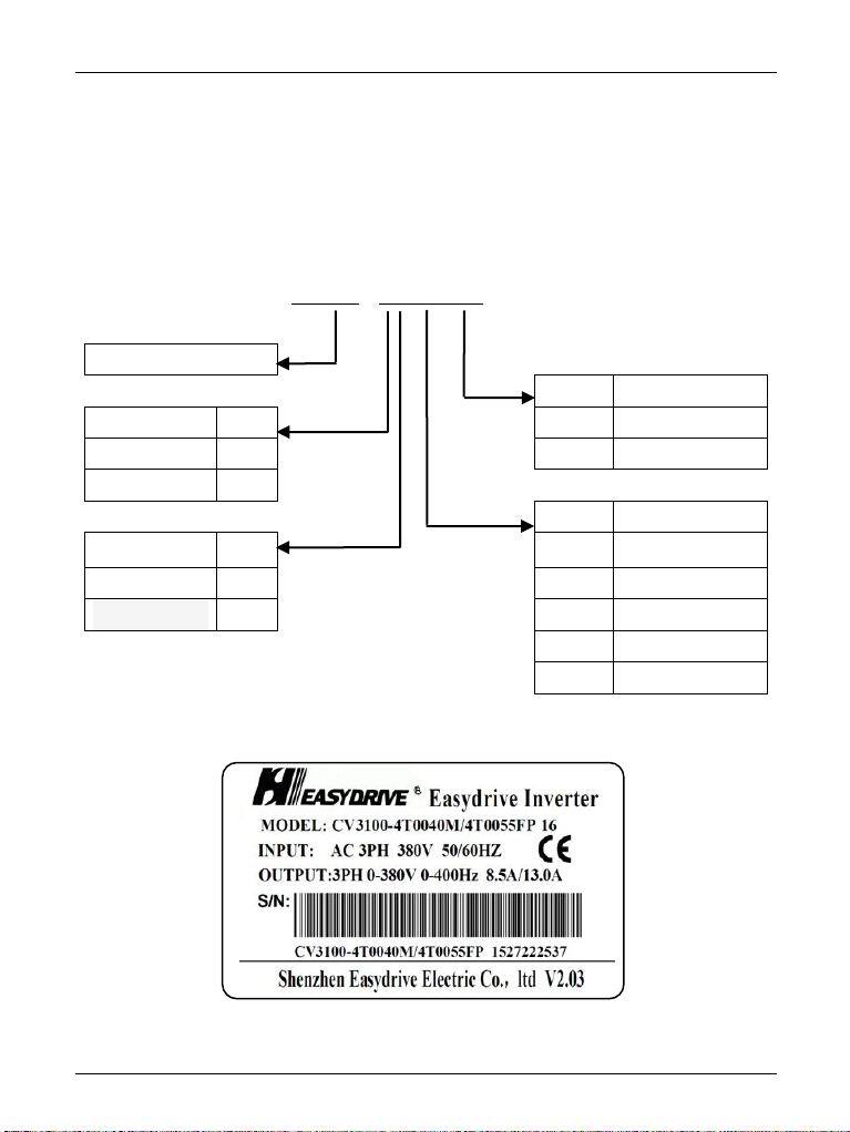
CV3100 series and MINI series high performance general purpose inverter instruction manual
1-5
(3) Negative-torque load
The occasion that needs the load to be raised produces the negative torque usually,
the inverter would generate over current or over voltage fault, and so it would trip, in
case of this, a braking resistor shall be mounted.
(4) Mechanical resonance point of load device
In the certain output frequency range, the inverter is likely to meet the mechanical
resonance point of load device, if that, the jumping frequency must be set to avoid this
point.
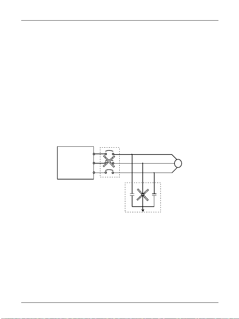
(5) Capacitor or pressure sensitive element that improves power factor
If there is a capacitor or varistor for lightning protection that improves power
factor mounted on the output side, they shall be removed, otherwise, the inverter
would trip for fault or the parts would be damaged, because output voltage of inverter
is the type of impulse wave. In addition, on the output side, it is suggested that air
switch and contactor would not be installed either, shown as diagram 1-3. (If the
switch unit has to be mounted on the side of output, the output current of inverter must
be zero when the switch operates.)
Diagram 1-3 Inverter output side never mounted with a capacitor
(6) Run at over 50Hz.
If the inverter has to run at over 50Hz, the applicable speed range of motor
bearing and mechanical equipment must be guaranteed in addition to considering the
vibration and noise of motor, and please inquire before inverter runs.
(7) Electronic heat protection value of motor
When a motor chosen is applicable, the inverter can provide the motor with heat
protection. If the motor doesn’t match with the rated capacity of inverter, the
protection value must be adjusted or other protection measures must be taken, to
guarantee the motor runs safely.