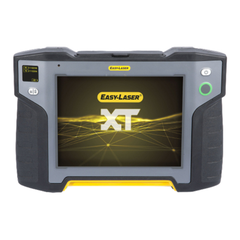
Easy-Laser E960 User manual

TURBINE GUIDE
English
05-0712 Revision 2.0
E960


CONTENT
INTRODUCTION 1
Service and calibration 3
Travelling with your measurement system 4
E960 TURBINE 5
System Easy-Laser® E960-A 5
System Easy-Laser® E960-B 5
Prepare the work 5
Assemble Laser transmitter 6
Using support beam 6
Using vertical support beam 7
Using arms 7
Assemble Detector 8
Using short stroke bracket 8
Using long stroke bracket 9
Beam extensions 10
Using sliding bracket 10
Preparations 11
Check the environment 11
Mount the laser transmitter 11
Rough align laser beam 12
Align the laser beam 13
Reference target 13
Adjust the measuring probe 14
Measure 15
Enter distance 16
Register values 16
Result 17
Result table view 17
Result 3D view 17
Result graph view 18
Tolerance 19


1
INTRODUCTION
Easy-Laser AB
Easy-Laser AB develops, manufactures and markets Easy-Laser®measurement and
alignment equipment based on laser technology.
We have more than 25 years of experience from measurement tasks in the eld and
product development. We also provide measurement service, which means that we
ourselves use the equipment we develop, and continuously improve it. Because of this
we dare to call ourselves measurement specialists.
Do not hesitate to contact us about your measurement problems. Our expertise will
help you solve it in an easy way.
Declaration of conformity
Equipment: Easy-Laser®product range
Easy-Laser AB declares that the Easy-Laser®product range is
manufactured in conformity with national and international regulations.
The system complies with, and has been tested according to the
following requirements:
EMC Directive 2014/30/EU
Low Voltage Directive 2014/35/EU
Laser Classication Europe: SS_EN 60825-1
USA: CFR 1040.10/11
RoHs Directive 2011/65/EU
WEEE Directive 2012/19/EU
R&TTE Directive 1999/5/EC
The calibration of the equipment fully complies with ISO9001:2008 #7.6
For Bluetooth®devices: This device complies with Part 15 of the FCC Rules.
Operation is subject to the following two conditions:
(1) this device may not cause harmful interference
(2) this device must accept any interference received, including interfer-
ence that may cause undesired operation.
Disposal of old electrical and electronic equipment (Applicable through-
out the European Union and other European countries with separate col-
lection programs)
This symbol, found on product or on its packing, indicates that this prod-
uct should not be treated as household waste when disposed of.
It should be handed over to an applicable collection point for the recycling of electrical
and electronic equipment. By ensuring this product is disposed correctly, you will help
to prevent potential negative consequences to the environment and human health. For
more detailed information about the recycling of this product, please contact your local
city oce, household waste disposal service or the retail store where you purchased
this product.
Quality certicate
Easy-Laser AB is ISO 9001:2008 certied. Certicate number 900958.
Easy-Laser AB conrm, that our products are produced according to applicable na-
tional and international regulations and standards. All components are checked before
assembly and nal products are tested in functionality and visually checked before
delivery
The calibration of the equipment fully complies with ISO9001: 2008 #7.6

2
Horizontal
Limited warranty
This product is manufactured under Easy-Laser’s strict quality control system. Should
the product fail within three (3) years from the date of purchase under normal usage
conditions, Easy-Laser will repair or replace the product free of charge.
1. Using new or refurbished replacement parts.
2. Exchange the product with a product that is new or which has been manufactured
from new or serviceable used parts and is at least functionally equivalent to the
original product.
Proof of purchase date should be conrmed, and sent together with a copy of the origi-
nal purchase document.
Warranty is valid under normal usage described in the user’s manual appended with
the product. The warranty comprises failure on Easy-Laser®product that could be
related to material and/or fabrication errors. The warranty is valid only in the country
of purchase.
The warranty is not valid in the following cases:
• If the product is broken due to mishandling or incorrect operation
• If the product has been exposed to extreme temperature, calamity, chock or high
voltage.
• If the product has been modied, repaired or disassembled by unauthorized per-
sonnel.
Compensation for possible damage due to failure on Easy-Laser®product is not in-
cluded in the warranty. Freight cost to Easy-Laser is not included in the warranty.
Note!
Before delivery of the product for warranty repair, it is the responsibility of the buyer
to backup all data. Data recovery is not included in the warranty service and Easy-
Laser is not responsible for data that may be lost or damaged during transit or repair.
Lithium Ion battery limited warranty
Lithium ion batteries inevitably lose power during their lifetimes, depending on usage
temperatures and the number of charging cycles. Therefore, the internal rechargeable
batteries used in the E-series are not included in our general 2-year warranty. There
is a 1 year warranty for the battery capacity not to fall below 70 % (a normal change
means that the battery must have more than 70 % capacity after more than 300 charg-
ing cycles). A 2 year warranty applies if the battery becomes unusable because of a
manufacturing fault or factors that Easy-Laser AB could be expected to have control
of, or if the battery displays abnormal loss of capacity in relation to use.

3
Horizontal
Safety precautions
Easy-Laser®is a laser instrument in laser class 2
with an output power normally less than 1 mW, which
requires the following safety precautions:
• Never stare directly into the laser beam
• Never aim the laser beam at anyone else’s eyes.
Note!
Opening the laser units can result in hazardous radiation, and will invalidate the
manufacturer warranty.
If starting the machine to be measured would result in injuries, the possibility to un-
intentionally start it must be disabled before mounting the equipment, for example by
locking the switch in the o position or removing the fuses. These safety precautions
should remain in place until the measurement equipment has been removed from the
machine.
Note!
The system should not be used in explosive risk areas.
Service and calibration
Our Service centres will quickly assist you if your measurement system need to be
repaired or when it is time for calibration.
Our main Service centre is located in Sweden. There are several local Service centres
that are certied to carry out limited service and repair. Contact your local Service
centre rst before sending your equipment for service or repair. All Service centres are
listed on our web site under Service and Calibration.
Before sending your measuring system to our main Service centre, please ll in the
online Service and Repair report.
Manuals as PDF
You can download our manuals in pdf format from our website. The pdf’s are also
available on the USB memory stick that is delivered with most systems.
EasyLink
The new version of our database program EasyLink is available on the USB memory
stick that is delivered with most systems. You can always download the latest version
from easylaser.com>download>software.

4
Horizontal
Travelling with your measurement system
When travelling by airplane with your measurement system we strongly recommend
that you check which rules apply for each airline company. Some companies/countries
have limitations for checked baggage when it comes to items including batteries. For
information about Easy-Laser® batteries, please see system unit details in the end of
this manual. It is also good practice to remove the batteries from the equipment, when
possible, e.g. D22, D23 and D75.
Specications for built-in rechargeable batteries
Easy-Laser
Part No.
Type Voltage Output Capacity Included in Part No.
03-0757 Li-Ion 3.7 V 43 Wh 11600 mAh 12-0418, 12-0700
03-0765 Li-Ion 3.7 V 2.5 Wh 680 mAh 12-0433, 12-0434, 12-0509, 12-0688, 12-0702, 12-0738,
12-0752, 12-0759, 12-0758, 12-0846, 12-0790, 12-0789
03-0971 Li-Ion 3.7 V 8.5 Wh 2300 mAh 12-0617, 12-0618, 12-0823, 12-0845
03-1052 Li-Ion 3.7 V 1.5 Wh 380 mAh 12-0746, 12-0747, 12-0776, 12-0777, 12-0791
03-1055 Li-Ion 3.7 V 34 Wh 9200 mAh 12-0748
12-0953 Li-Ion 3.7 V 7.4 Wh 2000 mAh 12-0944, 12-0943
12-0952 Li-Ion 7.4 V 39.22 Wh 5300 mAh 12-0961 (2 pcs)
Compatibility
The E-series is not compatible with previous analogue units from the D-series. You can
however continue to use previous brackets.
Disclaimer
Easy-Laser AB and our authorized dealers will take no responsibility for damage to
machines and plant as a result of the use of Easy-Laser®measurement and alignment
systems.
Copyright
© Easy-Laser 2017
We might change and correct the manual in later issues without further information.
Changes to the Easy-Laser® equipment may also aect the accuracy of the informa-
tion.
May 2017
Fredrik Eriksson
Quality Manager, Easy-Laser AB
Easy-Laser AB, PO Box 149, SE-431 22 Mölndal, Sweden
Phone: +46 31 708 63 00, E-mail: info@easylaser.com
Web: www.easylaser.com

5
E960 TURBINE
System Easy-Laser® E960-A
Part no. 12-0710
This system is suitable for gas turbines
and smaller steam turbines. Measures
diameters 150–1700 mm [5.9”–67”].
The detector bracket comes with a
slidable tube, making it possible to
measure several positions in a row
without moving the bracket.
System Easy-Laser® E960-B
Part no. 12-0711
System suitable for larger turbines.
Measures diameters 200–1700 mm
[7.8”–67”] as standard, and up to 4500
mm [177”] with accessory brackets. The
detector bracket has a probe stroke of 60
mm [2.4”], which is convenient when
nearby bore diameters vary a lot.
Note!
For a complete technical data, please see Manual.
Prepare the work
• Get hard copies of drawings with distances and diameters.
• Determine tolerances according to drawings, specication or standards.
• Assemble all brackets (as far as possible) in advance according to drawings.
• Check battery status of laser and display. Extra AA batteries for laser and display
(Note! Alkaline type only)
• Chalk for marking

6
E960 turbine
Assemble Laser transmitter
Using support beam
1. Select a horizontal support beam, long enough to rest on both sides with good
margin.
2. Use as short bracket as possible to maintain stability.
3. Mount the laser transmitter approximately at the middle of the support beam using
the square nuts.
4. Slide the magnets onto the support beam.
Offset hub
Laser transmitter
Laser beam angle adjustment
Magnet base
Mounting threads for
vertical support beam.
Support beam
Slide magnets onto the support beam Mount the offset hub Mount the laser transmitter

7
E960 turbine
Using vertical support beam
Use the third vertical beam to increase stability if the horizontal beam is extended with
one or more sections.
Support beam
Using arms
If needed, you can use extension arms to mount the laser transmitter. The arms are
100–500 mm.
Note!
The arms are not included in the E960 system, but delivered as an option.
Offset hub
Laser aperture
Adjustable arms
Support pin
Magnet attachment

8
E960 turbine
Assemble Detector
1. Select a horizontal support beam and extensions, long enough to rest on both sides
with good margin.
2. Mount the detector with bracket in the middle of the support beam (± 25 mm).
3. Attach probe with extension rods (approximately measuring radius – 120mm).
4. Slide the magnets in place. When using long support beams (>2.5m) it may be
necessary to readjust the magnet xation screws in order to maintain the laser
beam vertically in center.
5. Place the detector in the middle of the rods of the movable slide.
Using short stroke bracket
Part no. 12-0438
Measuring probe with a stroke of 10 mm. The slidable tube makes it possible to mea-
sure several positions in a row without moving the bracket. Suitable for gas turbines
and smaller steam turbines.
Extendable aluminium beam
Slidable tube
Detector slide
Measuring probe
A B C D
Included measuring probes:
A: Short ball top
B. Ball top
C. Cylinder top
D. Magnetic cylinder top
Magnet base
Detector slide mounted
without tube (left).
Detector mounted to receive
laser beam from opposite side
(right). Also possible with tube.

9
E960 turbine
Mount slidable tube
Using long stroke bracket
Part no. 12-0715
Measuring probe with a stroke of 60 mm. Suitable for larger turbines.
Extendable aluminium beam
Detector slide
Measuring probe
Magnet base

10
E960 turbine
Beam extensions
It is possible to extend the support beams. Mount three extension plates on one of the
aluminum beams. Slide the second beam onto the extension plates. See image below.
Using sliding bracket
It is not possible to slide in a turbine segment. Sliding brackets can only be used in
support bearings.
When measuring in tops-on condition, the self-center bracket is replaced with light
weight slide bracket. The slide bracket is useful in diameters up to 3m.
Slide bracket min. Ø120 mm [4.72”]
Part No: 12-0455
For bores Ø120–250 mm [4.72”–9.84”], width Min. 60 mm
[2.36”].
Slide bracket min. Ø200 [7.87”]
Part No: 12-0543
For bores Ø200–350 mm [7.87”–13.78”], width Min. 80 mm
[3.15”].
Slide bracket min. Ø300 mm [11.81”]
Part No: 12-0510
For bores Ø300–500 mm [11.81”–19.68”], width Min. 100 mm
[3.94”].

11
E960 turbine
Preparations
Check the environment
• Check that the turbine has a uniform temperature. Mainly important if the turbine
partly has been exposed to direct sunshine.
• Check that the laser, detector and brackets are covered from direct sunlight from
roof windows or other sources. Direct light (sun, strong lights or welding) into the
sensor may result in uctuating measurements and has to be prevented.
• Check that the ambient temperature is within the operating range of the EasyLa-
ser: 0 to 50 degrees.
• Check that airow or wind does not enter the measurement area, especially not
close to the laser source. To further reduce inuence, use appropriate lter set-
tings.
• Check for vibrations, low and mid frequencies, that may interfere with the mea-
surement. If found, identify the source and take actions to reduce the vibrations. In
case vibrations re-mains, use measurement lter (see the user manual).
• Check that rain can not enter into the measurement area
• Refrain from using mobile phone or communication radio while taking a reading.
• Clean all measurement points for oil, grease and other substances using grease
cleaner
• Remove any burr, welding spatter etc. Ensure that no original material is removed
during cleaning.
It is highly recommended that nal measurement is done during the night time when
there is less interfering work ongoing and the temperature has become stable (around
midnight).
Mount the laser transmitter
The laser should be placed on a stable and rigid place, free from air ow, vibrations
and sunshine. A welded structure xed to the ground or the turning gear bearing may
be suitable locations.
Check the following:
• Magnets are seated a machined surface, without tension.
• All magnets have full contact with the surface. If not, release and tighten screws.
• All screws on the bracket are properly tightened (but do not overtighten).
• Make sure that the laser transmitter battery is replaced to avoid interrupting the
measurement.
Note!
The ne adjustment screw on the tilting table must not exceed its maximum position.
That might damage the threads of the screw. See also Techdata in Manual.

12
E960 turbine
Rough align laser beam
The visual targets are used for laser beam prealignment and should be placed at the
rst and last bearing seating.
Part no. 12-0443
1. Place the ruler at the bearing pocket and move the adjustable side to t
the diameter.
2. Read the diameter and divide by two.
3. Switch on the laser.
4. Adjust the laser beam to the far target center. Use the angular adjustment screws
on the laser transmitter.
5. Adjust the laser beam to the target close to the laser. Adjust beam using the oset
adjustments.
6. Repeat until beam passes both target centers as accurate as possible. The laser
bracket may have to be moved if the parallel oset adjustment screws reach the
limit.
7. Remove targets.

13
E960 turbine
Align the laser beam
If extra high accuracy is required, for example during a nal inspection, the beam may
be precisely aligned to the reference surfaces. Note, this is not necessary during normal
corrective adjustment work.
Reference target
The purpose of a reference target is to monitor that the laser beam remain in its origi-
nal position during the measurement within the specied tolerance. Reasons for devia-
tion may be temperature changes, sun light or someone touching the laser.
1. Place the reference target at the far end of the turbine.
2. Select and to display the reference target.
3. The rst time you select the command, a window is displayed. Select which detec-
tor you want to use as reference detector and press OK.
Function buttons
Zero set displayed value.
Return to the absolute value.
Close target. You can also close by pressing OK.
1. Place the detector at the reference point furthest
away from the laser transmitter.
2. Turn the detector to position 9 o’clock position and
select .
3. Turn detector to 3 o’clock and select .
4. Adjust horizontal error to zero with the angular
adjustment screw.
5. Turn detector to 6 o’clock and adjust
vertical error to zero.
6. Move the detector close to the laser transmitter and
repeat step 2-5 to adjust the oset.
Repeat until both reference points are zero.
Angular adjustment screw
Vertical adjustment screw
Offset adjustment screws

14
E960 turbine
Adjust the measuring probe
1. Place the detector in the measurement position.
2. Adjust the probe length to the radius.
3. Turn the probe to position 6.
4. Adjust the detector vertically and horizontally to the centre of the laser beam.
5. Adjust the detector xture so that the probe runs parallel to the surface to be mea-
sured.
The measuring principle is the same for both long and short
stroke bracket. The probe rod is very easily adapted to each
diameter with extensions of different length.
Before measuring, please check that you have mounted the bracket and probe correctly.
If the bracket has been mounted skewed, the values will be incorrect. Image below show
a linebore measurement, but the same principle apply to turbines.
Make sure it is the same distance
Green line = correct
Red dotted line = incorrect

15
E960 turbine
Measure
You can use the program Half circle or Multi-
points. Here the program Half circle is used.
Please note that the order of measurement or
distances is not dependent on laser position.
First measurement point may therefore be the
most distant from the laser.
Note!
Face the laser transmitter from the detector. Then 9 o’clock is to the left, as in
the measuring programs.
The measurement probe at 9 o’clock. The measurement probe at 3 o’clock. The measurement probe at 6 o’clock.
+
-
+
-

16
E960 turbine
Enter distance
Press and enter the distance to the rst mea-
surement object.
Or Select to enter several distances.
For more information, see Manual.
Register values
Press to register a value. The Measurement position view is displayed. Register
values on three positions. You can register values with or without using inclinometer
values.
With inclinometer values
The inclinometer values are displayed. It is pos-
sible to register points anywhere.
1. Press to register rst position. A red
marking is displayed.
2. Turn outside of the red marking.
3. Press to register second position.
4. Turn outside of the red markings.
5. Press to register third position.
6. Select to measure next position.
Without inclinometer values
With the inclinometer values hidden, you are
prompted to register points at three positions.
Press to register values.
Inclinometer values on
Inclinometer values off
The measurement probe at 9 o’clock. The measurement probe at 3 o’clock. The measurement probe at 6 o’clock.
Distance
Table of contents
Other Easy-Laser Measuring Instrument manuals
Popular Measuring Instrument manuals by other brands

Michell Instruments
Michell Instruments OptiCal user manual

Enotec
Enotec COMTEC 6000 ATEX GasEx Installation and operation manual

PeakTech
PeakTech 5225 operating manual

TESTO
TESTO Smart Probes 115i instruction manual

APAR
APAR AR500 operating instructions

Modern Water
Modern Water OVA 7000 Routine Service Manual