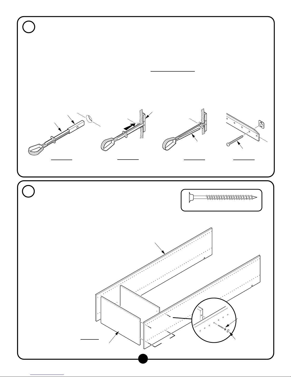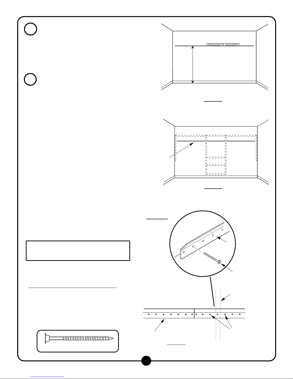
If a n y o f th e v e rtic a l a n e ls a re n o t w ith in 3 " o f a s tu d , a
to g g le b o lt is n e e d e d to a tta c h th e tra c k to th e w a ll. T o
d e te rm in e th e lo c a tio n o f th e to g g le b o lt(s ), h o ld o n e o f
th e tra c k s o v e r th e lin e , tig h t to th e c o rn e r. M a rk th e
hole locations near the studs and vertical anels
(kee ing track level).
F ig u r e 3
NO TE: D o not use the holes directly behind the
vertical panels, use the holes one space aw ay,
especially in corners
NO TE: If toggle bolts are required they m ust be
in s ta lle d p r io r to a tta c h in g th e tra c k to th e w a ll.
R e fe r to p a g e .
M easure the rem aining closet w idth. M ark and cut the
re m a in in g tra c k to le n g th w ith a h a c k s a w . M a rk th e
holes near the vertical anels.
For S tandard D ryw all/W allboard/Sheetrock:
For holes m arked at studs, d rill a ilo t h o le w ith a 1 /8 "
d rill b it. A tta c h th e tra c k to w a ll u s in g th e # 8 x 5 0 m m
screw s.
Figure 3a. N O T E : D o n o t le a v e th e e n d o f
the track unsupported, it m ust be attached to the
w a ll
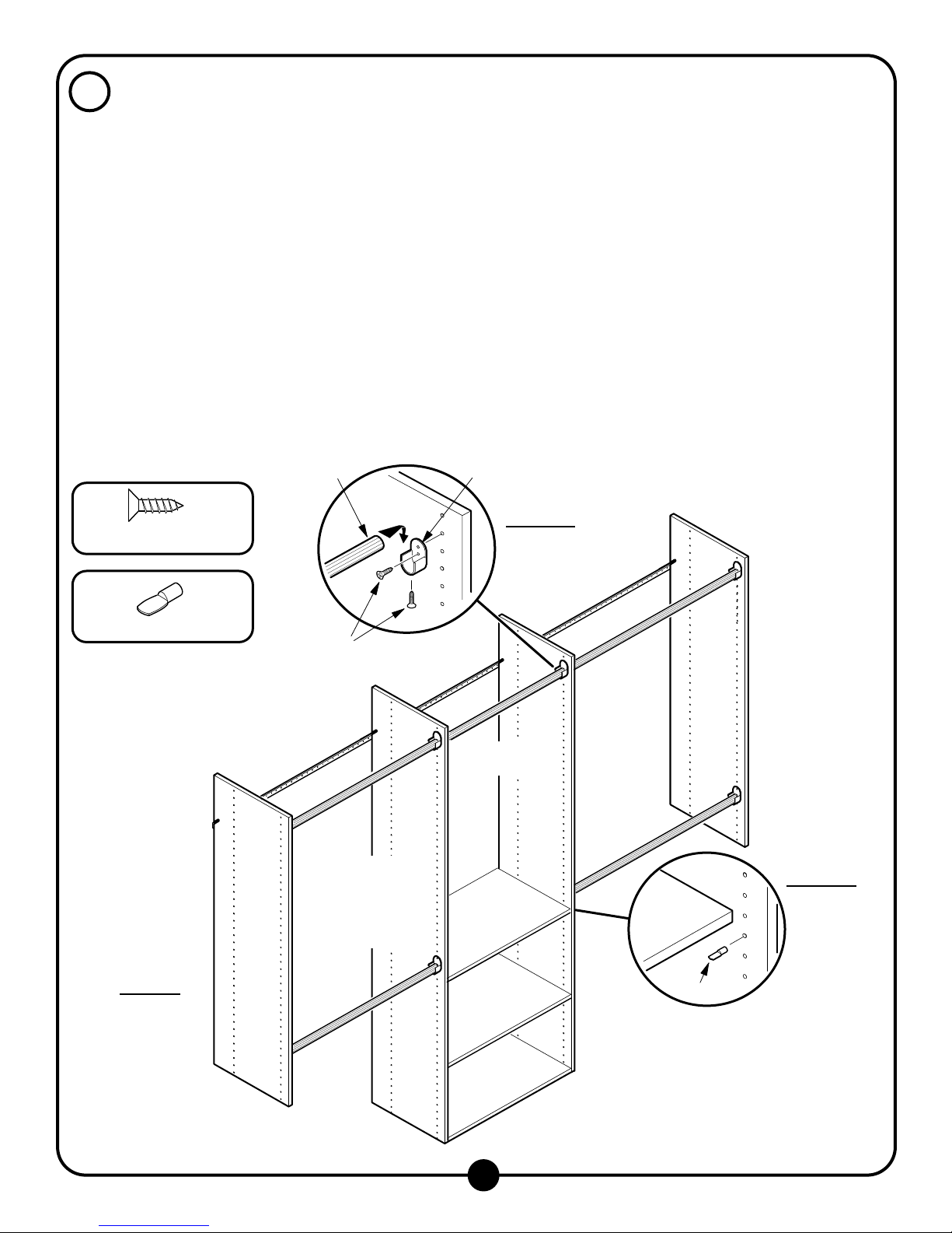
Vertical Panel
Location
2
Figure 3
#8 x 50m m S crew
Track
Track
M ark holes around
vertical anel for
e ith e r a s tu d o r a
toggle bolt
Figure 3a
#8 x 50m m S crew
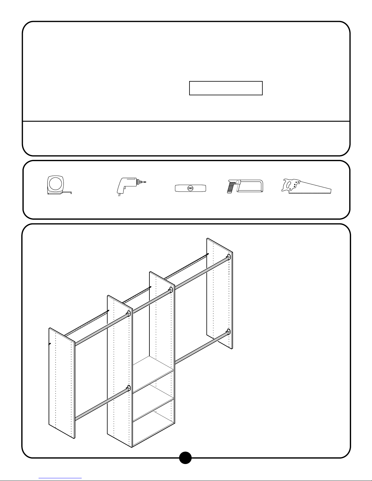
R em ove existing closet rod, shelf, and shelf su ort.
If, d e s ire d , fill h o le s in la s te r a n d re a in t c lo s e t.
W h e n fillin g h o le s , m a rk th e s e lo c a tio n s , a s th e y
generally m ark the location of studs.
U sing a level, draw a line across the back of the
c lo s e t, 7 6 " a b o v e flo o r. The 76" height w ill ut the to
of the verticals 84" above the floor, and rovide 41"
for double hanging clothes. The track height can be
adjusted de ending on the individual needs.
Figure 1
L o c a te s tu d s . If th e s tu d s a re n o t m a rk e d fro m S te 1 ,
ta w all or use an electronic stud finder to locate
s tu d s . M a rk w a ll 1 /2 " b e lo w h o riz o n ta l lin e . S tu d s
(2 x 4) are usually located on 16" centers m easured
fro m th e le ft o r rig h t s id e .
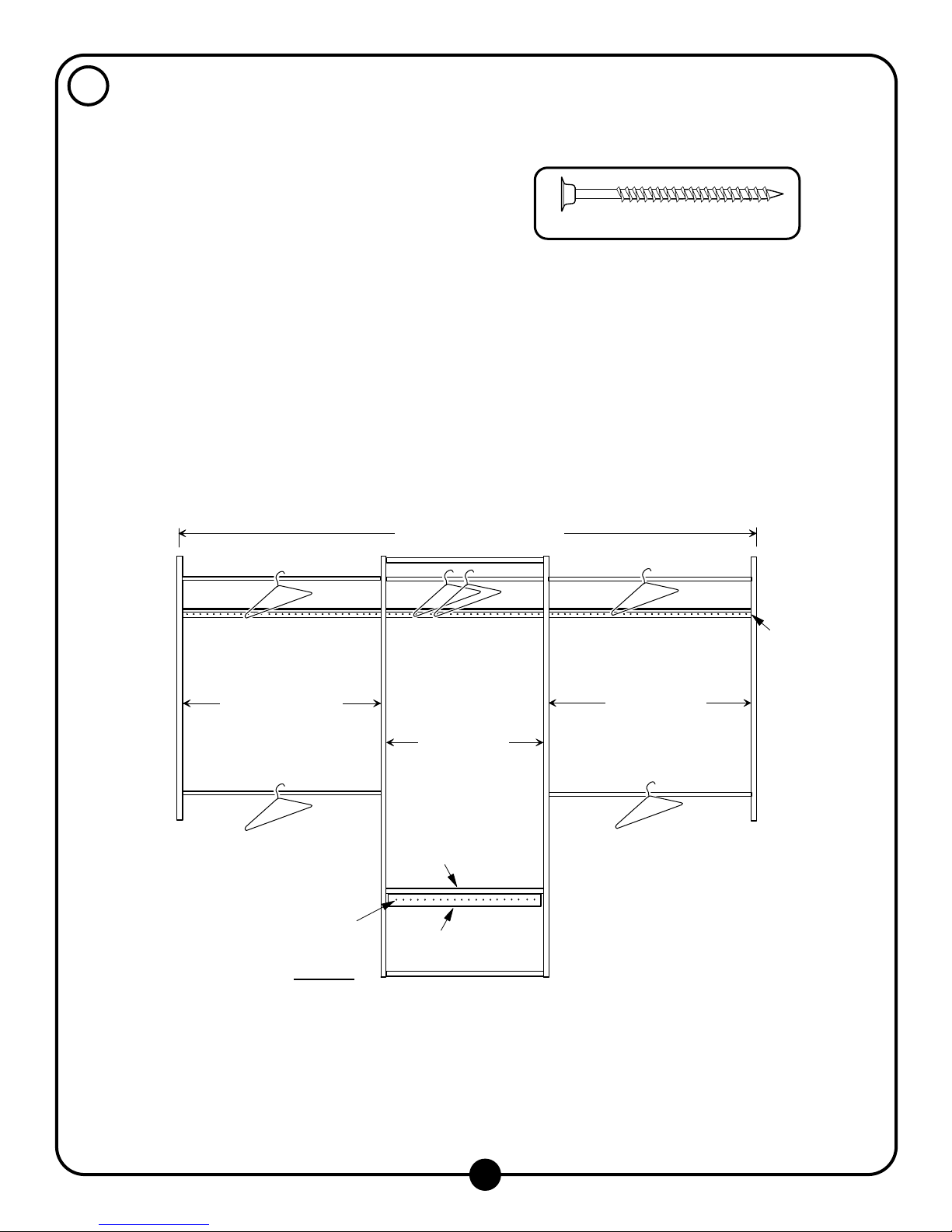
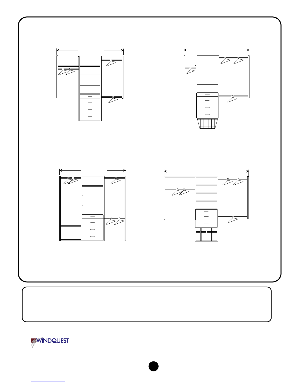
Lay out closet design to determ ine a roxim ately
w here vertical anels w ill be located. S ee Figure 7
o n a g e 5 fo r d im e n s io n s . M a rk th e v e rtic a l a n e l
lo c a tio n s o n th e w a ll b e lo w th e h o riz o n ta l lin e .
Figure 2
1
2
R em ove E xisting S helving
A ttach Track
Figure 2
M ark vertical anel
locations - see Figure
7 on age 5 for
dim ensions
Level line 76"
fro m th e flo o r,
then m ark stud
locations
Figure 1