Easydor PUSH User manual

Easydor
Wire Free Door Operator
PUSH
Fitting and Operating Guide
For a PUSH side installation
The instructions for installation of the Easydor are provided for those persons who
have the technical skill, capability and familiarity in the field of operators and
closing devices for swing doors. Any person who feels that they cannot satisfy those
requisites, should not attempt installation of the Easydor. If an Easydor is installed
incorrectly and subsequently the services of a Fireco engineer are required, a call-out
charge will be incurred.
Clockwise PUSH Open
Anti Clockwise PUSH Open

Introduction
This manual provides system description, installation instructions, operating instructions,
troubleshooting recommendations, and a replacement parts listing for the Easydor door operator.
Easydor is an automatic door opening and closing device that permits automatic operation of single
or double right hand or left hand doors measuring 910mm to 1220mm wide and weighing up to
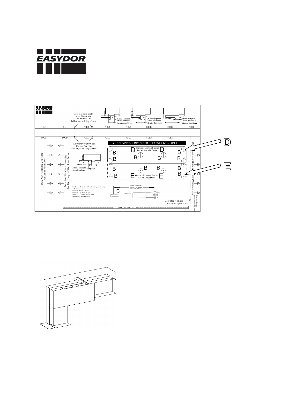
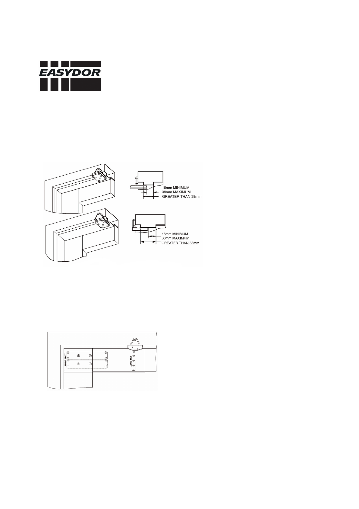
113 g. The door operator device mounts on a parallel-arm push-side configuration or on a standard
mount pull-side configuration.
Easydor allows the door to open manually or by a remote transmitter device. As the door closes
Easydor generates an electrical charge that restores power to the operator battery. If the door is
operated via remote transmitter more often than it is opened manually, the door closing cycle may
not supply enough power to charge the battery and permit remote operation.
Easydor is an extreme-duty, low-energy door opener designed for institutional, high-traffic manual
opening applications that occasionally requires powered operation. A regenerative drive system
charges an onboard battery pac , eliminating the need for electrical power.
Easydor should be applied to doors using our 80/20 guideline:
• Apply Easydor to a door that will be cycled manually approximately 80 times per day
and cycled automatically approximately 20% or less per day.
When applied using this 80/20 guideline, Easydor will self-generate all the power it needs to eep its
field-replaceable onboard battery pac charged for up to 12 years and in some cases longer.
A fully charged battery can open a door up to 2000 times in a row with little impact on the product’s
overall usability--even if there are periodic fluctuations from the 80/20 guideline.
For example 25% automatic use for one day is not a problem, so long as that level of
automatic use is not sustained.
Easydor utilizes a hibernation feature to reduce battery consumption after a predefined
period of door inactivity. In a school or university setting, Easydor can sit idle for months
during the summer brea without any significant battery drain. Simply activate the door once
manually to wa e Easydor from its hibernation mode.

Applica ility
This manual is applicable to Easydor wireless door opener for a zero reveal door frame.
The instructions for installation of the Easydor are provided for those persons who have the
technical s ill, capability and familiarity in the field of operators and closing devices for swing doors.
Any person who feels that they cannot satisfy those requisites, should not attempt installation of the
Easydor. If an Easydor is installed incorrectly and subsequently the services of a Fireco engineer are
required, a call-out charge will be incurred.
Important Information
1. This product is intended for interior use only.
2. The battery should not be installed in the transmitter until the operator and door arm
installation are complete.
3. An operating door creates pinch hazards. Be careful ma ing operating adjustments
while the door is moving.

Easydor fixings and tools required
Main Box Door Activation Pad(s) x2
•9 Philips Head screws 2 stub screws (already inserted)
•6 silver washers 2 large soc et head bolt
•2 steel mounting pins 2 wall mount screws
•1 blac domed soc et head bolt
•2 small soc et head bolts (Triangular door frame mount)
•
Fitting template
Bag 1 - 3 Blac Philips Head screws, 2 Blac soc et head bolts.
Bag 2 - 6 Philips Head screws, 6 silver washers, 2 steel mounting pins, 2 large soc et head bolts, 2
small soc et head bolts.
Bag 3 - 4 wall mount screws.
2 small soc et head bolts 9 Philips Head screws 6 Silver Washers
1 Blac domed 2 Steel mounting 4 Push button wall mount screws
Soc et-head bolt Pins
Tools Required Mounting Templates
Spanner to fit 11mm A - Operator Arm Brac et
Philips Head Screwdriver B - Easydor Body Brac et
4mm & 6mm drill bit C - Arm Length Reference
Tape Measure
Imperial Allen Key set: 3/16”, 9/64” & 1/16”

Easydor fitting instructions
PUSH door
Step 1 - Line up template to top of door.

Step 2 - If door thic ness is 1.5” or less, use outline ‘D’ on Template. If door thic ness more than
1.5”, use outline ‘E’ on Template. The door ‘Stop Width’ cannot exceed 20mm otherwise the body of
the Easydor will foul with it when in the closed position.
Step 3 - Align Template to the edge of the door
Step 4 - Using a centre punch, mar the mounting hole location
Step 5 - Using a square, mar the centre line of the arm pivot onto the underside and face of the
door frame (using template)

Step 6 - Using 2 blac soc et head screws from Bag 1, attach mounting brac et to frame mounting
triangle.
Step 7 - Using a centre punch, mar the door arm pivot brac et hole locations.
Step 8 - Using a 4 ½ mm drill bit, drill the door arm pivot brac et holes.
Step 9 - Secure the door arm pivot brac et to the underside and face of the frame, using 3 Blac
Philips head screws from Bag 1.

Step 10 - Using a 5mm drill bit, drill the holes for the operator mounting brac et.
Step 11 - Align the operating mounting brac et to the drilled holes in the door and fix using 6 x
Phillips head screws and washers from Bag 2 but do not tighten.
Step 12 - If using operating brac et Template D, leave a 12.7mm space between the operating
brac et and the top of the door.
If using Operating brac et B – Upper fold - 60.32mm from top of the door.
Lower fold - 44.45mm from top of door.

Step 13 - Tighten screws.
Step 14 - If the operator is being mounted to Template D, tighten the operator mounting pins from
Bag 2 into the lower threaded holes in the mounting brac et using an adjustable spanner. If the
operator is being mounted to Template E, tighten the operator mounting pins into the upper
threaded holes using adjustable spanner.
Step 15 - Place the operator mounting cover over the operator mounting brac et.

Step 16 - With the battery pac attachment arm facing the hinges, position Easydor body onto the
mounting pins.
Step 17 -
Using 2 large soc et head bolts from Bag 2, secure Easydor body to mounting pins, using
an Allen ey.
Step 18 - With the door arm coupling screws facing up, and the door arm touching the face of the
door, position the larger end of the door arm onto the operator output shaft.
Step 19 - Tighten the door arm coupling screws evenly, one ¼ turn at a time, until fully tight.
Step 20 - With the Easydor arm elbow touching the face of the door, slide on the adjustable arm
brac et and align with the Easydor adjustable arm end pivot.
Adjust Easydor arm as necessary to align.

Step 21 - Using an Allen ey, tighten the side loc ing screws of the adjustable arm brac et.
Step 22 – Remove the domed soc et head bolt from the operating arm brac et, insert the Easydor
arm to the operating arm brac et and reaffix the domed soc et head bolt.
Easydor ody not shown for clarity

Step 23
-
Insert Allen ey into hole above battery slot. Adjust cloc wise to increase spring tension
to ensure door closes in a controlled manner.

Door Activation Pads
The door activation pads should be installed within a range of 25 meters and 1.5 meters above the
floor.
Step 1 - Using a Philips Head screwdriver, undo the 2 stub screws.
Step 2 - Remove front Steel Plate.
Step 3 - Using Philips Head screwdriver, remove 2 silver Pan Head screws from ‘Inner Plate
Assembly’.
Step 4 - Remove Inner Plate Assembly.
Step 5 - Using a 4mm Drill bit, drill pilot holes in Door Activation Pad Bac plate of Door Activation
Pad.
Step 6 - Using a drill-but appropriate to the wall screw, drill into the wall. Insert rawl plugs if
necessary.
Step 7 - Using 2 wall mount screws from Bag 3, use Philips Head screwdriver to fix Door Activation
Pad Bac plate to the wall in the pre-drilled holes.
Step 8 - With the spring facing towards you, match up Inner Plate Assembly ta ing care to ensure
no wires are caught.
Step 9 - Using a Philips Head screwdriver, fix the Inner Plate Assembly to the Door Activation Pad
Bac plate using the 2 silver Philips Pan Head screws previously removed.
Step 10 - Fix Front Plate to Activation Pad.
Repeat process for pad on the other side of the door.

Programming the door
Step 1 - Using 9/64” Allen Key, remove Base Plate Cover if it is attached.
Step 2 - Connect battery pac to the Easydor Body using the 3 pin connector & soc et, ensuring the
wires do not interfere with the Base Plate Cover.

Step 3 - Push and hold Enter & Select uttons together for 3 seconds.
Step 4 - 4 LEDS will flash green repeatedly for a few seconds. A red closed position LED will then
remain lit.
Step 5 - With the door in the closed position, press the Enter utton. The LEDs will then flash
green, then red.

Step 6 - Open the door till fully ajar, press Enter utton. The open position LEDS will then flash
green.
Step 7 - Release door.
Step 8 - With door in the closed position, press Enter utton. A second non-labelled LED will flash
green then stop.
Step 9 - Stand clear from the door. The door will then quic ly open halfway and then close.
Step 10 - Press and hold Enter utton until DS9 LED flashes to confirm you have exited the
programming.
Varia le Open and Close Options
To enter programming mode:
Step 1 - Press and hold Enter and Select uttons for 3 seconds. 4 green LEDS will flash.
Step 2 - Wait for the 4 green LEDS to stop flashing, and 1 CLS green LED to light.
Step 3 - Press and release Select utton. The green CLS LED will go off, and the green OP LED
position light will come on.
Step 4 - Press Select utton until desired operating mode is highlighted by green LED
Step 5 - Press Enter utton once.
Step 6 - Press Enter utton again and hold for 3 seconds.
You will now have exited the programming.

Open and Close Time - Rotate thumbwheel cloc wise to increase speed of door operation.
Rotate thumbwheel anti-cloc wise to decrease speed of door operation. The LEDS will light to
indicate strength.
Press Enter utton once.
Press Enter utton again and hold for 3 seconds. You will now have exited the programming.
Maximum Opening Force - Rotate thumbwheel cloc wise to increase opening force of operation.
Rotate thumbwheel anti-cloc wise to decrease speed of door operation. The LEDS will light to
indicate strength.
Press Enter utton once.
Press Enter utton again and hold for 3 seconds. You will now have exited the programming.
Hold Open - Rotate thumbwheel cloc wise to increase Hold Open time. Rotate anti-cloc wise to
decrease Hold Open time. The LEDS will light to indicate time set.
Press Enter utton once.
Press Enter utton again and hold for 3 seconds. You will now have exited the programming.
Finally
Holding Battery Pac firmly against Easydor body, slide base cover onto the body and secure using
Allen Key and the 2 small soc et head bolts from Bag 2.
Popular Door Opening System manuals by other brands

Von Duprin
Von Duprin 98/9927 installation instructions

BFT
BFT VISTA EMERGENCY Installation and user manual

Corbin Russwin
Corbin Russwin DC6210 Series installation instructions

Assa Abloy
Assa Abloy CloserPlus Ramp Norton XF460 installation instructions

WSS
WSS SPRINT NOVA 80 Assembly and operating instructions

Dormakaba
Dormakaba TS 98 XEA Mounting instructions

Dorma
Dorma RTS Series quick start guide

Cal-Royal
Cal-Royal N900 Series installation instructions

Verkada
Verkada AC62 install guide

Dormakaba
Dormakaba ED250 Service manual

Keyautomation
Keyautomation WIND Instructions and warnings for installation and use

Entrematic
Entrematic EM PSW250 User's manual and operating instructions