manuals.online logo
Brands
  1. Home
  2. •
  3. Brands
  4. •
  5. Eaton
  6. •
  7. Accessories
  8. •
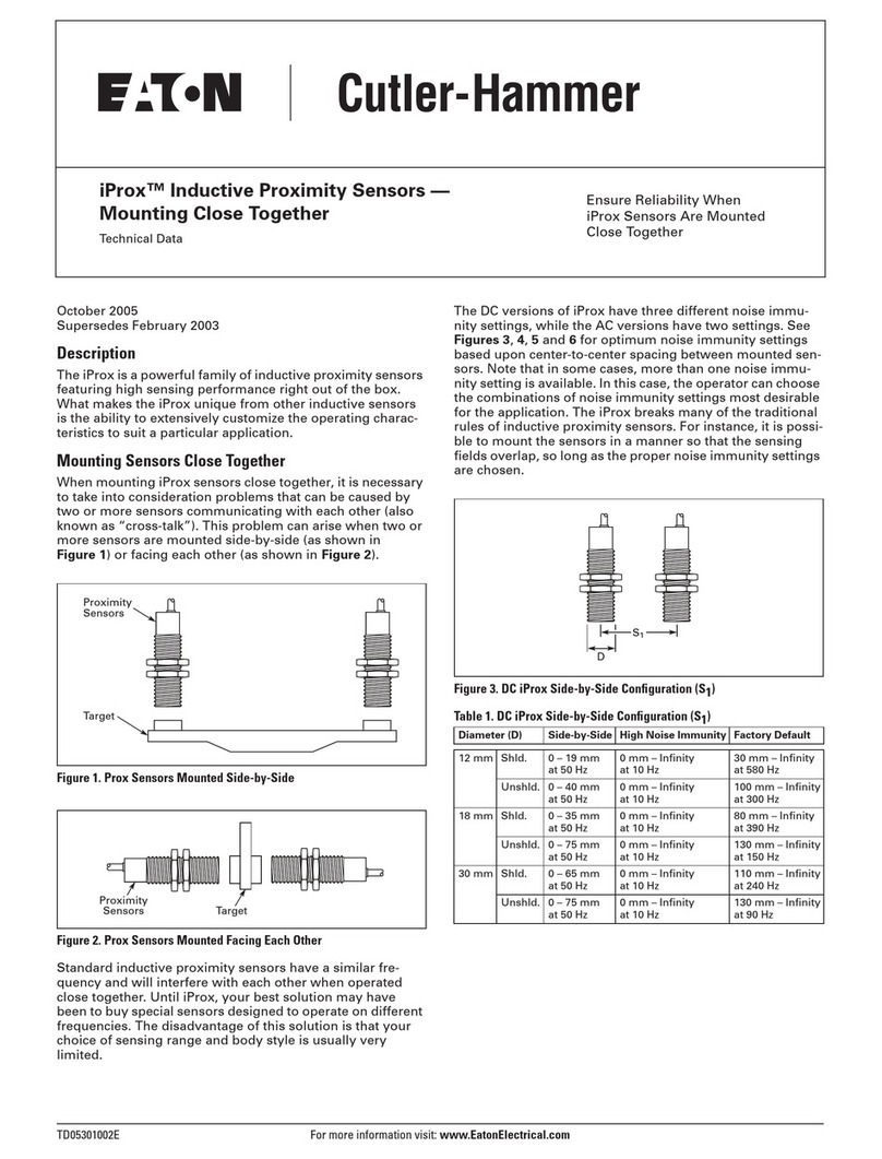
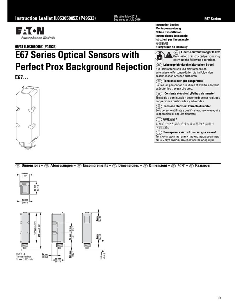
  9. Eaton 50 Series User manual

Eaton 50 Series User manual

P50796 Rev 07 P50796 Rev 07
Effective: June 2010 Effective: June 2010
INSTRUCTION MANUAL:
ENHANCED 50 SERIES PHOTOELECTRIC SENSORS
THRU-BEAM
MODELS COVERED IN THIS MANUAL
AC/DC Models
Style Output Type
6-Foot Cable
Integral Micro Quick
Disconnect Integral Mini Quick Disconnect
Pigtail Micro
Quick Disconnect
No Time
Delay
With Time
Delay
No Time
Delay
With Time
Delay
No Time
Delay
With Time
Delay
No Time
Delay
With Time
Delay
200-Foot Thru-Beam
Source (Emitter)
N/A 1150E-6513 N/A 1150E-6543 N/A 1150E-6504 N/A 1150E-6534 N/A
200-Foot Thru-Beam
Detector (Receiver)
Solid-State Relay 1250E-6513 1250E-8513 1250E-6543* 1250E-8543* 1250E-6503 1250E-8503 1250E-6533 1250E-8533
Electromechanical
Relay
1250E-6514 1250E-8514 N/A N/A 1250E-6504 1250E-8504 1250E-6534 1250E-8534
500-Foot Thru-Beam
Source (Emitter)
N/A 1151E-6513 N/A 1151E-6543 N/A 1151E-6504 N/A 1151E-6534 N/A
500-Foot Thru-Beam
Detector (Receiver)
Solid-State Relay 1251E-6513 1251E-8513 1251E-6543* 1251E-8543* 1251E-6503 1251E-8503 1251E-6533 1251E-8533
Electromechanical
Relay
1251E-6514 1251E-8514 N/A N/A 1251E-6504 1251E-8504 1251E-6534 1251E-8534
DC Models
Style
Emitter LED Output Type
6-Foot Cable
Integral Euro (Micro) Quick
Disconnect Integral Mini Quick Disconnect
Pigtail Euro (Micro) Quick
Disconnect
No Time
Delay
With Time
Delay
No Time
Delay
With Time
Delay
No Time
Delay
With Time
Delay
No Time
Delay
With Time
Delay
200-Foot Thru-Beam
Source (Emitter)
N/A 1150E-6517 N/A 1150E-6547 N/A 1150E-6507 N/A 1150E-6537 N/A
200-Foot Thru-Beam
Detector (Receiver)
NPN/PNP 1250E-6517 1250E-8517 1250E-6547 1250E-8547 1250E-6507 1250E-8507 1250E-6537 1250E-8537
500-Foot Thru-Beam
Source (Emitter)
N/A 1151E-6517 N/A 1151E-6547 N/A 1151E-6507 N/A 1151E-6537 N/A
500-Foot Thru-Beam
Detector (Receiver)
NPN/PNP 1251E-6517 1251E-8517 1251E-6547 1251E-8547 1251E-6507 1251E-8507 1251E-6537 1251E-8537
* Versions of these sensors are available with a non-isolated output. Non-isolated output models end in -45, ex. 1350E-6545. For more information, consult wiring diagrams on Page 4.
WARNING
THESE PRODUCTS ARE NOT DESIGNED, TESTED, OR RECOMMENDED FOR
USE IN HUMAN SAFETY APPLICATIONS.
DURING INSTALLATION, CORRECT POWER CONNECTIONS MUST BE
MADE FIRST TO ENSURE FAIL-SAFE SHORT CIRCUIT PROTECTION OF THE
OUTPUTS. REFER TO THE WIRING DIAGRAMS IN THIS MANUAL.
DO NOT USE TOOLS TO APPLY TORQUE DIRECTLY TO SENSOR BODY.
ALIGN SENSOR BY HAND BEFORE TIGHTENING MOUNTING HARDWARE.
ADJUSTMENT POTS ARE 3/4 TURN DEVICES. ANY RESISTANCE
ENCOUNTERED WHILE ADJUSTING THESE POTS INDICATES YOU HAVE
REACHED THE ADJUSTMENT LIMIT STOP. TURNING PAST THIS STOP
WILL DAMAGE THE SENSOR.
USE ONLY THE ADJUSTMENT TOOL PROVIDED OR SUITABLE
SCREWDRIVER WHEN TURNING ADJUSTMENT POTS OR SETTING SWITCH
POSITIONS. SHARP OBJECTS CAN DAMAGE THE SENSOR AND RESULT IN
ELECTRICAL SHOCK.
ENSURE THE PRODUCT IS CONNECTED TO THE CORRECT POWER SUPPLY
FOR THE APPLICATION. REFER TO THE WIRING DIAGRAMS IN THIS
MANUAL.
AC/DC CONNECTOR VERSION SENSORS ARE EQUIPPED WITH AN AC-
TYPE CONNECTOR. THE USE OF DC POWER WITH AC-TYPE CONNECTORS
MAY NOT CONFORM WITH ESTABLISHED STANDARDS.
Page 1Page 4
INTRODUCTION
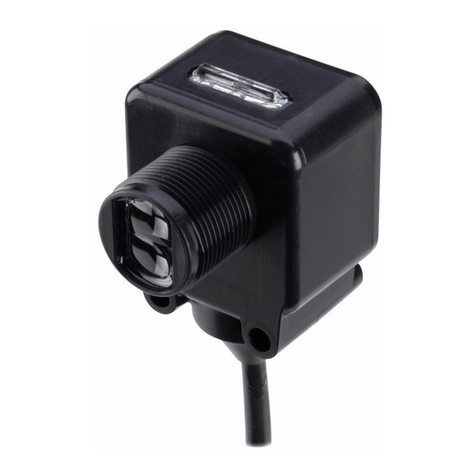
Enhanced 50 Series photoelectric sensors offer flexibility, durability, and
high optical performance in a low-cost self-contained package. Each
sensor features several mounting options and a low-gain indicator for quick
installation and easy alignment. Models are available for operation with
DC power, or AC and DC power in a single unit. Sensors are wired using a
6-foot power cable, body-mounted quick disconnect mini connector, body
mounted quick disconnect micro (AC/DC Micro or Euro (Micro)) connector, or
quick disconnect micro (AC/DC Micro or Euro (Micro)) connector on a short
cable pigtail. All sensors have built-in light/dark selection, and modes are
available with timing features that include on-delay, off-delay, and one-shot
delay.
An Enhanced 50 thru-beam photoelectric sensor installation consists of an
emitter and a receiver positioned on opposite sides of a detection zone. The
emitter emits infrared light, which is detected by the receiver. The receiver
output switches on when this beam of light is either blocked (when set in
dark operate mode) or completed (in light operate mode).
A complete system consists of an emitter and receiver mounted such that
the emitter directs its light beam at the receiver and the receiver is aimed
to detect the beam. The emitter and receiver can be separated by up to 61
meters (200 feet) using standard range models and 152 meters (500 feet)
using extended range models.
WIRING DIAGRAMS (Pin numbers are for reference only; rely on pin location when wiring)
Operating Voltage Models Cable Models Mini-Connector Models
(Face View Male Shown)
Micro-Connector Models
(Face View Male Shown)
10-40V DC Thru-Beam Emitters
Thru-Beam Receivers
12-240V DC or
24-240V AC with
Solid-State Relay
Thru-Beam Emitters
Thru-Beam Receivers
with Isolated AC/DC
Output
Thru-Beam
Receivers with
Non-Isolated AC/DC
Output
12-240V DC or
24-240V AC with
SPDT EM Relay
Thru-Beam Emitters
Thru-Beam Receivers
1Connect load to the appropriate outlet for either sinking or sourcing operation.
2Connecting the test input to 0V DC allows you to switch the light source off for troubleshooting while leaving the sensor under power.
3Over current protection is to be provided in the field. Conductor size for 20 AWG: 5 amp; 22 AWG: 3 amp; 24 AWG: 2 amp.
BU
BR
BK
Test In
(+)
(
–
) OV Test In
(
–
)OV
(+) Test In
(
–
)OV
(+)
BU
WH NPN
PNP (
–
)OV
BK
BN (+)
Load
Load
(+)
(
–
)OV
PNP
NPN
Load
Load
(+)
(
–
)OV
PNP
NPN
Load
Load
BU
BR L1 (+)
L2 (
–
)
L2 (
–
)
L1 (+) L1 (+)
L2 (–)
BU
BK
WH
BR L1 (+)
L2 (
–
)
Isolated
AC/DC Output
L2 (
–
)
L1 (+)
Isolated
AC/DC Output
L1 (+)
L2 (
–
)
Isolated
AC/DC
Output
L1 (
–
)
L2 (+)
Load
BU
BR L1 (+)
L2 (
–
)
L2 (
–
)
L1 (+) L1 (+)
L2 (–)
BU
OR
BK
BR
WH N.C.
COM
N.O.
L2 (
–
)
L1 (+) L1 (+)
COM
N.O. N.C.
L2 (
–
)
L1 (+)
L2 (
–
)
COM
N.O. N.C.
P50796 Rev 07 P50796 Rev 07
Effective: June 2010 Effective: June 2010Page 2 Page 3
MOUNTING
The Enhanced 50 Series sensor features a 30 mm threaded base housing
and includes jam nut and washer. This allows mounting into any 1.25 inch
hole. Use caution to avoid cross-threading the jam nut on the sensor body.
A second mounting method is to use #10 hardware in the mounting holes of
the sensor. This is ideal for mounting the Enhanced 50 Series Sensor against
a wall, piece of equipment, rail, or mounting bracket.
After mounting, ensure gain adjustment is turned fully clockwise (receiver
only). See Warning on Page 1 concerning pot adjustment.
MOUNTING AND SETUP FOR THRU-BEAM MODELS
Mount the emitter and receiver units so they are aimed directly at each
other from opposite sides of the target. (The receiver should be on the dirtier
side because the light scattering effect of dirt collecting on the lens is less
significant if it takes place at the receiver.) Ensure the area of the target to
be detected will block the entire effective beam (see illustration to the right).
Apply power to both units.
Accurate sensing depends on proper alignment of the emitter and receiver.
To begin, the emitter and receiver must be positioned in rough alignment
so that emitter light is received by the receiver (check by placing a solid
object in front of the emitter beam—the output indicator on the receiver will
change state when the object blocks the beam and will change back when
the object is removed). If the output indicator does not change state, follow
this alignment method:
Move the receiver back and forth in the horizontal axis to find the extreme
positions where the output indicator on the receiver goes “OFF” (in dark
operate mode) or “ON” (light operate mode). Position the receiver midway
between the two extremes. Repeat this procedure for the vertical axis, then
tighten the receiver in place. Now repeat the final alignment procedure for
the emitter.
The alignment (red) indicator LED on the top of the sensor can aid in setup.
Even if the sensor is working properly, it may not be optimally aligned. If
this is the case, this red LED will be off, indicating a low gain condition.
Repeating the alignment procedure to clear this indication will maximize the
long-term reliability of the unit.
In short range applications, you may need to reduce the sensor sensitivity
by turning the gain adjustment counter-clockwise to account for object
transparency in the detection zone.
LIGHT OR DARK OPERATE MODES (FOR ALL MODELS)
All sensors are equipped with a light/dark operate selector switch. In Light
Operate mode, the sensor output is energized when the sensor “sees” light.
For a thru-beam sensor in light operate mode, the output will be energized
when an object is not present in the detection zone (as the receiver is
“seeing” the light from the emitter). For a thru-beam sensor in dark
operate mode, the output will be energized when an object is present in the
detection zone. In dark operate mode, the sensor output is energized when
the receiver does not “see” light.
SENSORS WITH TIMING FUNCTIONS
Sensors are available with time delay functions as shown in the model
table on page one of this installation guide. Sensors with built-in timing
capability can be configured in
four different modes using the
Delay Range switch on top of
the sensor. These modes are:
NO DELAY
In this mode, the time delay
functionality is disabled and
the sensor operates in the
same way as would a standard unit. For “No Delay,” the Delay Range switch
must be selected to “T/D” and both delay potentiometers turned fully CCW.
ON DELAY
In this mode, after an object enters the detection zone the delay timer starts
and the sensor output does not switch until the timer has timed out. For “On
Delay,” the Delay Range switch must be selected to “T/B” and the Delay On
potentiometer turned CW to the desired delay time. See Note A for toggling
between short and long delays.
OFF DELAY
In this mode, when an object exits the detection zone, the delay timer starts
and the sensor output does not switch until the timer has timed out. For “Off
Delay,” the Delay Range switch must be selected to “T/D” and the Delay Off
potentiometer turned CW to the desired delay time. See Note A for toggling
between short and long delays.
ONE-SHOT DELAY
In this mode, a change in the state of the light beam will result in a delayed
output pulse. The switch labeled “D.O./L.O.” determines whether the pulse
is initiated by the “light to dark” transition of the light beam of the “dark to
light” transition. In the D.O. switch position, the pulse is initiated by the “light
to dark” transition, while in the L.O. position the pulse is initiated by the
“dark to light” transition.
The Delay On potentiometer adjusts the delay of the time between the
initiating transition and when the output pulse actually begins. The Delay
Off potentiometer adjusts the duration of the output pulse. See Note A for
toggling between short and long delays.
Note A: The positions of the Delay Range switches determine the length
of time delay. When put into the “S” position, the respective delay
potentiometer works over a short time delay range of 0-1.5 seconds
(approximate). When put into the “L” position, the respective delay
potentiometer works over a time delay range of 0-15 seconds (approximate).
OPTICAL PERFORMANCE
All optical specifications are guaranteed to be the minimum performance
under clean conditions of any product delivered from stock. Typical
performance may be higher.
Dirt in the environment will affect optical performance by reducing the
amount of light the control receives. For best results, sensors should be used
at distances where excess gain is higher than 1.5 (1.5 times the amount of
sensing power required to detect an object under ideal conditions). Higher
excess gain will allow the sensor to overcome higher levels of contamination
on the lens.
Source Beam Pattern
The beam pattern is the area
containing all the light rays emitted by
the source. The detector must be
placed within the source beam pattern.
Detector Field-of-View
The field-of-view is the area which
can be seen by the detector. The
source unit must be placed within the
detector’s field-of-view for the
detection system to operate.
Effective Beam Diameter
For a thru-beam system, the effective beam is a “rod”
defined by the edge rays traced from the source lens to the
detector lens. The only source-generated light rays that the
detector sees are those that travel in a straight line from
the source lens to the detector lens. Note that the object
must fully block the beam in order to be detected.
Thru-Beam
1. 1151E/1251E
2. 1150E/1250E
10
1
1
0.3
10 1000
RANGE (feet)
RANGE (m)
EXCESS GAIN
100
1000
30.5 5030.3
100
1
2
SPECIFICATIONS
AC/DC
Electromechanical Relay Models
AC/DC
Solid-State Relay Models
DC Only
Models
Input Voltage 12 - 240V DC
24 - 240V AC
12 - 240V DC
24 - 240V AC
10 - 40V DC
Light/Dark Operation Switch selectable
Operating Temperature -13 to 122ºF (-25 to 50ºC)
Humidity 95% Relative Humidity; Non-Condensing
Case Material Fiberglass Reinforced Plastic
Lens Material Acrylic
Vibration IEC 60947-5-2 Part 7.4.2
Shock IEC 60947-5-2 Part 7.4.1
Protection Output Short Circuit, Overcurrent Protection and Reverse Polarity Protection
Enclosure Rating IP67
Output Load 3A @ 120V AC
3A @ 240V AC
3A @ 28V AC
300 mA @ 240V AC/DC 250 mA @ 40V DC
Response Time 15 mS 2 mS
Timer Timing Response 0 - 15 sec.
No Load Current <30 mA
Leakage Current (Maximum) — 1 mA @ 240V AC <10 µA
Emitter LED Infrared 880 nm
Indicator LEDs Yellow for Power; Green for Output; Red for Alignment
DIMENSIONS IN INCHES (MM)
Cable and Pigtail Connector* Versions AC/DC Micro or Euro (Micro)
Connector Versions
Mini Connector Versions
2.87
(73)
1.81
(46)
0.59
(15)
1.42
(36)
1.91
(48.5)
0.26 (6.5)
Dia.
0.21 (5.2) x0.32 (8.1)
Slot – 2 Places
0.31
(8)
0.16
(4)
2.87
(73)
1.81
(46)
0.59 (15)
0.55
(13.97)
1.42
(36)
1.91
(48.5)
0.21 (5.2) x0.32 (8.1)
Slot – 2 Places
0.31
(8)
0.16
(4)
2.87
(73)
1.81
(46)
0.59 (15)
0.70
(17.78)
1.42
(36)
1.91
(48.5)
0.21 (5.2) x0.32 (8.1)
Slot – 2 Places
0.31
(8)
0.16
(4)
* Pigtail length: 7.5” nominal
Red LED:
Alignment
Yellow LED:
Power
Green LED:
Output
Dark/Light
Operate Adjustment
Delay Range
Selection
Delay On
Potentiometer
Delay Off
Potentiometer
Sensitivity
Potentiometer
T/D L L
ON OFF
ONE
SHOT
SS
MAXMIN
D.O. L.O.
EXCESS GAIN CURVE

This manual suits for next models

60

Other Eaton Accessories manuals

Eaton CurrentWatch EDC Series Manual

Eaton

Eaton CurrentWatch EDC Series Manual

Eaton CDWA-01/3 Series Manual

Eaton

Eaton CDWA-01/3 Series Manual

Eaton IntelliView Series Manual

Eaton

Eaton IntelliView Series Manual

Eaton SVPD Series Operating instructions

Eaton

Eaton SVPD Series Operating instructions

Eaton E57P Series Manual

Eaton

Eaton E57P Series Manual

Eaton Crouse-Hinds GHG 515 User manual

Eaton

Eaton Crouse-Hinds GHG 515 User manual

Eaton NanoView E71 Series Manual

Eaton

Eaton NanoView E71 Series Manual

Eaton Arrow Hart AHAWC-DT-120W User manual

Eaton

Eaton Arrow Hart AHAWC-DT-120W User manual

Eaton GridAdvisor II Series User manual

Eaton

Eaton GridAdvisor II Series User manual

Eaton E65 SM Series Manual

Eaton

Eaton E65 SM Series Manual

Eaton E67 Series Manual

Eaton

Eaton E67 Series Manual

Eaton E65 Series Manual

Eaton

Eaton E65 Series Manual

Eaton GHG 521 User manual

Eaton

Eaton GHG 521 User manual

Eaton 450-N Manual

Eaton

Eaton 450-N Manual

Eaton Comet Series Manual

Eaton

Eaton Comet Series Manual

Eaton MPD-C-EXT User manual

Eaton

Eaton MPD-C-EXT User manual

Eaton Cutler-Hammer iProx Series Instruction manual

Eaton

Eaton Cutler-Hammer iProx Series Instruction manual

Eaton Powerware Series User manual

Eaton

Eaton Powerware Series User manual

Eaton CurrentWatch EAC Series Manual

Eaton

Eaton CurrentWatch EAC Series Manual

Eaton E55 Series Manual

Eaton

Eaton E55 Series Manual

Eaton 450-CSA Manual

Eaton

Eaton 450-CSA Manual

Eaton E67 Series Manual

Eaton

Eaton E67 Series Manual

Eaton CurrentWatch EGFL Series Manual

Eaton

Eaton CurrentWatch EGFL Series Manual

Eaton CurrentWatch EGF Series User manual

Eaton

Eaton CurrentWatch EGF Series User manual

Popular Accessories manuals by other brands

Quincy lab 140AE-1 operating manual

Quincy lab

Quincy lab 140AE-1 operating manual

HomePro ZIR000 user manual

HomePro

HomePro ZIR000 user manual

DOL 20SCR Technical user guide

DOL

DOL 20SCR Technical user guide

RAB Smart Task installation manual

RAB

RAB Smart Task installation manual

Kemppi KMS 300 quick guide

Kemppi

Kemppi KMS 300 quick guide

Stearns 57,500 Series Installation and service instructions

Stearns

Stearns 57,500 Series Installation and service instructions

iGuzzini TWILIGHT COPENAGHEN manual

iGuzzini

iGuzzini TWILIGHT COPENAGHEN manual

Adelaide Annexe & Canvas Avan Deluxe installation guide

Adelaide Annexe & Canvas

Adelaide Annexe & Canvas Avan Deluxe installation guide

OHAUS 5000 instruction manual

OHAUS

OHAUS 5000 instruction manual

HOME8 WLS1300 quick start guide

HOME8

HOME8 WLS1300 quick start guide

MAXBOTIX MaxSonar quick start guide

MAXBOTIX

MAXBOTIX MaxSonar quick start guide

ioSmart iSmart56 Installation and user guide

ioSmart

ioSmart iSmart56 Installation and user guide

Focusrite Scarlett 18i8 user guide

Focusrite

Focusrite Scarlett 18i8 user guide

Velleman ED38105 user manual

Velleman

Velleman ED38105 user manual

JumpSport SkyBounce user manual

JumpSport

JumpSport SkyBounce user manual

Prima-Temp PRIYA Instructions for use

Prima-Temp

Prima-Temp PRIYA Instructions for use

Tefcold BC85I-BC85I W user manual

Tefcold

Tefcold BC85I-BC85I W user manual

Vaisala WMS302 user guide

Vaisala

Vaisala WMS302 user guide

manuals.online logo
manuals.online logoBrands
  • About & Mission
  • Contact us
  • Privacy Policy
  • Terms and Conditions

Copyright 2025 Manuals.Online. All Rights Reserved.