manuals.online logo
Brands
  1. Home
  2. •
  3. Brands
  4. •
  5. Eaton
  6. •
  7. Accessories
  8. •
  9. Eaton E56M Manual

Eaton E56M Manual

WARNING
IN ORDER TO AVOID ELECTRIC SHOCK OR OTHER
POSSIBLE INJURY:
• DO NOT USE THIS PRODUCT FOR HUMAN SAFETY
APPLICATIONS. IT WAS NOT DESIGNED, TESTED, OR
RECOMMENDED FOR THIS USE.
• DO NOT USE THIS PRODUCT IN HAZARDOUS LOCATIONS
(E.G., EXPLOSIVE ATMOSPHERES). IT WAS NOT DESIGNED,
TESTED, OR RECOMMENDED FOR THIS USE.
• ENSURE THE PRODUCT IS PROPERLY WIRED TO THE CORRECT
POWER SUPPLY FOR THE APPLICATION. REFER TO THE
SPECIFICATIONS AND WIRING DIAGRAMS IN THIS MANUAL.
Instruction Leaet IL053007EN Effective October 2020
Introduction
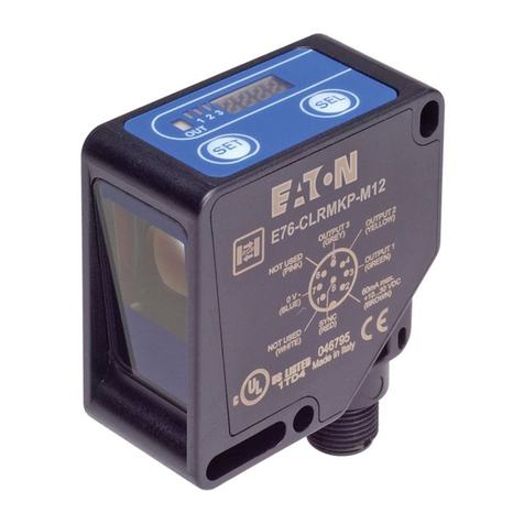
The Eaton E56 High Noise Immunity pancake-style proximity
sensor is a solid-state device used to detect metallic targets
at range. The E56 High Noise Immunity is available in two
different size categories with three sensing ranges: small
(4-inch mounting baseplate) with a 0.5 inch sensing range, and
large (5-inch mounting baseplate) with 1.0 and 1.5inch sensing
range versions. Connectivity is provided by a preinstalled
shielded cable. The sensor is mounted to a stainless steel
baseplate drilled for four-hole mounting. The E56 High
Noise Immunity inductive proximity sensor family provides
robustness and survivability in the most difficult application
environments. The sensor family is rated to 200 Volts/meter
of radiated noise and survives in high shock and high vibration
application environments. The E56 High Noise Immunity
enclosure meets the requirements of NEMATType 4, 4X, 6,
and 6P and is rated IP67 and IP68. Additional features include
complementary outputs 1NO/1NC on DC models, and output/
fault status indicator LEDs on applicable models. Sensors are
available in four-wire DC and two-wire AC versions.
Basic operation
A proximity sensor generates a sensing field in the vicinity of
the face of the sensor. When a metal object enters this field,
it disturbs the field in a way that is recognized by a detector
circuit, which then energizes the sensor output. E56 High Noise
Immunity sensors will detect all metals at similar distances,
and are officially range-rated against 4130 steel. The exact
distance at which a target is detected is dependent upon the
size, thickness, and metallic composition of the target.
To determine sensing distance with your target, see the
sensing field diagrams on Page 2. These diagrams serve
as a general reference and show where the target will be
detected for lateral slide-by) and axial (head-on) approaches.
These curves must be corrected for smaller-than-standard
targets and for targets composed of other metals. Standard
targets are listed on Page 2.
E56 High Noise Immunity
inductive proximity sensor
Table 1. Catalog numbering system
ote:N Not all possible combinations shown in the table are offered
as standard.
E56M B A D 05 A 20 L
Product family
E56M = E56 High Noise
Immunity
Size (in inches)
A= Baseplate: 4.0
Sensing head: ø 3.4
Sensing range: 0.5
B= Baseplate: 5.0
Sensing head: ø 4.5
Sensing range: 1.0
C= Baseplate: 5.0
Sensing head: ø 4.5
Sensing range: 1.5
Output type
A= Normally open
B= Normally closed
C= 1 Normally open
1 Normally closed
Voltage type
C= AC 2-wire
D= DC 4-wire
Connection
A= Shielded cable
Cable length
XX = Cable length (feet)
LED indication
L= Versions with
indicator LED
Sensing range
05 = 0.5 inch
10 = 1.0 inch
15 = 1.5 inch
2
Instruction Leaet IL053007EN
Effective October 2020
E56 High Noise Immunity
inductive proximity sensor
EATON www.eaton.com
Mounting considerations
All sensors should be mounted using four 3/8-inch bolts through the
mounting holes provided. A sensor can be mounted to any surface
without affecting sensor performance, but it is recommended to
use a solid base to ensure reliable operation. For all models, ensure
there is adequate distance between the sensor face and any
adjacent metals. See the diagrams below for isolation distances.
When E56 High Noise Immunity sensors are mounted side-by-side,
there is the possibility of interaction between the magnetic fields
of the sensors. This could cause unreliable operation. Follow the
limitations noted in the below illustration when mounting sensors
close to one another.
Sensor isolation minimum distances
Sensing
Sensing fields for the E56 High Noise Immunity sensor are shown
below. In addition to maximum sensing distances, these diagrams
illustrate the performance of the sensor as the target approaches
the sensing face in an axial (head-on) or lateral (side or slide-by)
manner. In these diagrams, the sensing distances shown are based
on standard target sizes and 4130 steel target material. Sensing
range will decrease if a target is used that is smaller than the
standard target size. See the table below for standard target sizes
for each size sensor.
Sensor type Sensor size
(baseplate) Standard target size
Small 4.0 inches 3 x 3 inches, 0.062 inch thick
Large (1.0 inch range) 5.0 inches 4 x 4 inches, 0.062 inch thick
Large (1.5 inch range) 5.0 inches 4 x 4 inches, 0.062 inch thick
Sensing eld diagrams
Detection for laterally approaching targets occurs at the point where
the target touches the envelope of the sensing curve as depicted
below. The curves must be corrected for smaller targets and will be
slightly different for other metals than 4130 steel.
Small sensor — 0.5 inch range
Lateral
Axial
Operate point
target moving
right to left
Operate point
target moving
left to right
Large sensor — 1.0 inch range
Lateral
Axial
Operate point
target moving
right to left
Operate point
target moving
left to right
Large sensor — 1.5 inch range
Lateral
Axial
Operate point
target moving
right to left
Operate point
target moving
left to right
Facing sensors — 6x sensing range
Sensor to background ferrous metal
3x sensing range
Sensor to background nonferrous metal
2x sensing range
Sensor to sideground metal below sensor face
baseplate contact ok
Sensor to sideground metal above sensor face
1/2 sensor diameter clearance required
Side-by-side sensors — 1x sensing range
3
Instruction Leaet IL053007EN
Effective October 2020
E56 High Noise Immunity
inductive proximity sensor
EATON www.eaton.com
Target positioning
To ensure reliable sensing performance, it is recommended to follow
the general guidelines regarding target positioning below.
• Axial (head on) approach — The target must be positioned so
that a projection of the target on the sensor face is centered
over the indicator area shown on the sensor face. If the target is
smaller than the indicator area, its axis should coincide with the
sensor axis.
• Lateral (side, slide-by) approach — Position the target at a
distance normally 50% of the rated axial sensing distance from
the sensor face.
Protection features
Built-in overload and short-circuit protection prevents damage to
sensors when the load current exceeds a safe level, and DC models
are additionally protected against reverse polarity. Protection levels
are shown in the specification table in this manual. For sensor
versions with LEDs, the LED indicator will flash if the overload or
short condition persists, and the cycle will repeat until the load current
returns or is corrected to a value below the protection threshold.
Wiring diagrams
Sensors should be mounted using four 3/8-inch bolts through the
mounting holes provided.
ote:N For all models, baseplate can be grounded through mounting hardware.
AC 2-wire models
LOAD
BK L1 or +V
L2 or -V
* NO/NC by model
WH
DC 4-wire models
GRN 0V
+V
WH (NO)
RED (NC)
BK
LOAD
LOAD
Approximate dimensions
Small diameter (4-inch baseplate)
Large diameter (5-inch baseplate)
Eaton
1000 Eaton Boulevard
Cleveland, OH 44122
United States
Eaton.com
© 2020 Eaton
All Rights Reserved
Printed in USA
Publication No. IL053007EN / Z24464
October 2020
Eaton is a registered trademark.
All other trademarks are property
of their respective owners.
E56 High Noise Immunity
inductive proximity sensor
Instruction Leaet IL053007EN
Effective October 2020
Periodic maintenance requirement
Periodic maintenance is required to ensure sensors perform to expectation, given the range of possible
operating conditions they can face. Semiannually, a standard 4130 steel target in the size shown in
the table below should be used to verify the “Maximum Sensing Distance” for every sensor. See the
table below for standard target sizes and rated maximum sensing distances. This measurement must
also consider the temperature in the sensing environment and account for the possibility of up to 10%
temperature drift as shown in the table below. Any sensor that fails this periodic Maximum Sensing
Distance test should be immediately replaced.
Specications
AC 2-wire DC 4-wire
Small (0.5 inch) Large (1.0 inch) Large (1.5 inch) Small (0.5 inch) Large (1.0 inch) Large (1.5 inch)
Operating voltage 65–130 Vac 60 Hz 10–30 Vdc
Load current (resistive) 1.25 A rms 250 mA
Load current (inductive) Make: 10 A rms for 3 cycles
Break: 1.25 A rms
250 mA
0.10 A lamp load
Burden current/burden resistor Burden resistor may be required for some 2-wire input applications
(example: PLC use)
<50 mA
Minimum load 15 mA rms N/A
Off-state leakage <4 mA <300 uA at 35 Vdc
Voltage drop <4 Vac <1.5 Vdc
Cable MIL-C-24643/43, type LS2SJ-16 2 conductor w/shield
20-foot length
MIL-C-24643/43, type LS4SJ-20 4 conductor w/shield
20-foot length
Circuit protection Overload protection to 6 A rms Overload, short circuit, reverse polarity
Dielectric withstand 1000 Vac between case and each conductor
>60 seconds, <1.5 mA
250 Vdc between case and each conductor
>60 seconds, <0.75 mA
Outputs Normally open or normally closed (by model) 1 x normally open, 1 x normally closed
Standard target size (4130 steel) 3 inch square,
0.062 thick
4 inch square,
0.062 thick
4 inch square,
0.062 thick
3 inch square,
0.062 thick
4 inch square,
0.062 thick
4 inch square,
0.062 thick
Head-on sensing range 0.5 ± 0.05 inch 1.0 + 0.22 inch
– 0.08 inch
1.5 + 0.50 inch
– 0.12 inch
0.5 ± 0.05 inch 1.0 + 0.22 inch
– 0.08 inch
1.5 + 0.50 inch
– 0.12 inch
Hysteresis 5–20% 5–30% 5–40% 5–20% 5–30% 5–40%
Weight <5 lb <6 lb <6 lb <5 lb <6 lb <6 lb
Response time <50 msec
Switch stabilization <500 msec
Operating temperature –20 to 70 °C (–4 to 158 °F)
EMC MIL-STD-461G (RS103 at 200 V/m) above deck usage (see Note)
Enclosure rating NEMA 4, 4X, 6, 6P IP67, IP68
Approvals MIL-PRF-24711B
Indicator LED (selected models) Target present - LED on, target absent - LED off, internal fault - slow blink, external fault - fast blink
Vibration MIL-STD-167-1, Type 1
Shock MIL-S-901, Grade A, Type A, Class I lightweight equipment
Humidity MIL-STD-202, Method 103B, test condition B
Materials of construction 316 stainless steel base, PA66 cover
Patents Covered by US patent 7,296,485 and EU patent 1728058 B1. Other patents pending.
ote:N All units referenced in this document meet the requirements of MIL-STD-461G CS114 with the exception of DC
models under certain specific conditions. DC models meet the requirements of the bulk cable injection test under all
conditions, above and below deck, but do not meet the requirements when the power conductor is tested individually
above deck, outside of a shielded junction box, over the 2 MHz–30 MHz frequency range.
Other Eaton Accessories manuals

Eaton GFX User manual

Eaton

Eaton GFX User manual

Eaton xComfort CEMU-01/ Series User manual

Eaton

Eaton xComfort CEMU-01/ Series User manual

Eaton ALL-PRO MSS1301LW User manual

Eaton

Eaton ALL-PRO MSS1301LW User manual

Eaton CurrentWatch EPRM Series User manual

Eaton

Eaton CurrentWatch EPRM Series User manual

Eaton CurrentWatch EDC Series Manual

Eaton

Eaton CurrentWatch EDC Series Manual

Eaton Crouse-hinds series User manual

Eaton

Eaton Crouse-hinds series User manual

Eaton CurrentWatch EGF Series User manual

Eaton

Eaton CurrentWatch EGF Series User manual

Eaton 738r User manual

Eaton

Eaton 738r User manual

Eaton Magnum PXR ACB Manual

Eaton

Eaton Magnum PXR ACB Manual

Eaton Cutler-Hammer iProx Series Instruction manual

Eaton

Eaton Cutler-Hammer iProx Series Instruction manual

Eaton E57P Series Manual

Eaton

Eaton E57P Series Manual

Eaton E58 Series Manual

Eaton

Eaton E58 Series Manual

Eaton E55 Series Manual

Eaton

Eaton E55 Series Manual

Eaton OSP10M User manual

Eaton

Eaton OSP10M User manual

Eaton Metalux User manual

Eaton

Eaton Metalux User manual

Eaton EX RT PDU User manual

Eaton

Eaton EX RT PDU User manual

Eaton E67 Series Manual

Eaton

Eaton E67 Series Manual

Eaton Crouse-Hinds IF 1744 Setup guide

Eaton

Eaton Crouse-Hinds IF 1744 Setup guide

Eaton EAFR-01 User manual

Eaton

Eaton EAFR-01 User manual

Eaton CurrentWatch EGF Series Manual

Eaton

Eaton CurrentWatch EGF Series Manual

Eaton E67 Series Manual

Eaton

Eaton E67 Series Manual

Eaton Series NRX Manual

Eaton

Eaton Series NRX Manual

Eaton 450-CSA Manual

Eaton

Eaton 450-CSA Manual

Eaton Arrow Hart AHAWC-DT-120W User manual

Eaton

Eaton Arrow Hart AHAWC-DT-120W User manual

Popular Accessories manuals by other brands

Quincy lab 140AE-1 operating manual

Quincy lab

Quincy lab 140AE-1 operating manual

HomePro ZIR000 user manual

HomePro

HomePro ZIR000 user manual

DOL 20SCR Technical user guide

DOL

DOL 20SCR Technical user guide

RAB Smart Task installation manual

RAB

RAB Smart Task installation manual

Kemppi KMS 300 quick guide

Kemppi

Kemppi KMS 300 quick guide

Stearns 57,500 Series Installation and service instructions

Stearns

Stearns 57,500 Series Installation and service instructions

iGuzzini TWILIGHT COPENAGHEN manual

iGuzzini

iGuzzini TWILIGHT COPENAGHEN manual

Adelaide Annexe & Canvas Avan Deluxe installation guide

Adelaide Annexe & Canvas

Adelaide Annexe & Canvas Avan Deluxe installation guide

OHAUS 5000 instruction manual

OHAUS

OHAUS 5000 instruction manual

HOME8 WLS1300 quick start guide

HOME8

HOME8 WLS1300 quick start guide

MAXBOTIX MaxSonar quick start guide

MAXBOTIX

MAXBOTIX MaxSonar quick start guide

ioSmart iSmart56 Installation and user guide

ioSmart

ioSmart iSmart56 Installation and user guide

Focusrite Scarlett 18i8 user guide

Focusrite

Focusrite Scarlett 18i8 user guide

Velleman ED38105 user manual

Velleman

Velleman ED38105 user manual

JumpSport SkyBounce user manual

JumpSport

JumpSport SkyBounce user manual

Prima-Temp PRIYA Instructions for use

Prima-Temp

Prima-Temp PRIYA Instructions for use

Tefcold BC85I-BC85I W user manual

Tefcold

Tefcold BC85I-BC85I W user manual

Vaisala WMS302 user guide

Vaisala

Vaisala WMS302 user guide

manuals.online logo
manuals.online logoBrands
  • About & Mission
  • Contact us
  • Privacy Policy
  • Terms and Conditions

Copyright 2025 Manuals.Online. All Rights Reserved.