Kramer VA-1Hs User manual

Kramer Electronics, Ltd.
USER MANUAL
Model:
VA-1Hs
UXGA Sync Shifter

Contents
i
Contents
1Introduction 1
2Getting Started 1
2.1 Quick Start 2
3Overview 3
4Your VA-1Hs UXGA Sync Shifter 4
5Connecting the VA-1Hs UXGA Sync Shifter 4
6Operating the VA-1Hs 5
6.1 Resetting the Memory 6
7Technical Specifications 6
Figures
Figure 1: VA-1Hs UXGA Sync Shifter Functions 4
Figure 2: Connecting the VA-1Hs UXGA Sync Shifter 5
Tables
Table 1: VA-1Hs UXGA Sync Shifter Functions 4
Table 2: VA-1Hs Technical Specifications 6

Introduction
1
1
1 Introduction
Welcome to Kramer Electronics! Since 1981, Kramer Electronics has been
providing a world of unique, creative, and affordable solutions to the vast
range of problems that confront the video, audio, presentation, and
broadcasting professional on a daily basis. In recent years, we have
redesigned and upgraded most of our line, making the best even better! Our
1,000-plus different models now appear in 11 groups1
Thank you for purchasing the Kramer TOOLS VA-1Hs UXGA Sync Shifter,
which is ideal for home-entertainment, multimedia, and presentation
applications.
that are clearly
defined by function.
Each package includes the following items:
•The VA-1Hs UXGA Sync Shifter
•Power adapter (5V DC input)
•This user manual2
2 Getting Started
We recommend that you:
•Unpack the equipment carefully and save the original box and
packaging materials for possible future shipment
•Review the contents of this user manual
•Use Kramer high-performance high-resolution cables3
1 GROUP 1: Distribution Amplifiers; GROUP 2: Switchers and Matrix Switchers; GROUP 3: Control Systems;
GROUP 4: Format/Standards Converters; GROUP 5: Range Extenders and Repeaters; GROUP 6: Specialty AV Products;
GROUP 7: Scan Converters and Scalers; GROUP 8: Cables and Connectors; GROUP 9: Room Connectivity;
GROUP 10: Accessories and Rack Adapters; GROUP 11: Sierra Products
2 Download up-to-date Kramer user manuals from our Web site at http://www.kramerelectronics.com
3 The complete list of Kramer cables is on our Web site at http://www.kramerelectronics.com

KRAMER: SIMPLE CREATIVE TECHNOLOGY
Getting Started
2
2.1 Quick Start
This quick start chart summarizes the basic setup and operation steps.

Overview
3
3 Overview
The Kramer VA-1Hs UXGA Sync Shifter is a high-performance sync delay
corrector that can be used for any computer graphics video signal from
VGA to UXGA.
When sending a computer graphics video signal from a PC to a monitor via
a long-distance display cable, the delay between the picture information and
the sync may cause a horizontal shift on the display. The VA-1Hs
compensates by shifting the sync accordingly, so that the picture is properly
displayed.
To achieve the best performance:
•Use only good quality connection cables
1
to avoid interference,
deterioration in signal quality due to poor matching, and elevated noise
levels (often associated with low-quality cables).
•Avoid interference from neighboring electrical appliances that may
adversely influence signal quality and position your Kramer VA-1Hs
away from moisture, excessive sunlight and dust
1 Available from Kramer Electronics on our Web site at http://www.kramerelectronics.com

KRAMER: SIMPLE CREATIVE TECHNOLOGY
Your VA-1Hs UXGA Sync Shifter
4
4 Your VA-1Hs UXGA Sync Shifter
Figure 1and Table 1define the VA-1Hs.
s
Figure 1: VA-1Hs UXGA Sync Shifter Functions
Table 1: VA-1Hs UXGA Sync Shifter Functions
#
Feature
Function
1 INPUT 15-pin HD (F) Connector Connects to the computer graphics video signal source
2 OUTPUT 15-pin HD (F) Connector Connects to the display acceptor
3 5V DC Connector +5V DC for powering the unit
4 SHIFT MOVE Button Push to move the image on the display to the left
5 SHIFT MOVE Button Push to move the image on the display to the right
6 ON Button Push to enable image shifting
7 ON LED Illuminates when the unit is powered ON
5 Connecting the VA-1Hs UXGA Sync Shifter
To connect the VA-1Hs, as the example in Figure 2illustrates, do the
following:
1. Turn OFF the power on all devices.
2. Connect the computer graphics video signal cable to the INPUT connector
on the VA-1Hs.
3. Connect the OUTPUT connector to the acceptor display.
4. Connect the 5V DC power adapter to the power socket and connect the
adapter to the mains electricity (not shown in the illustration).
5. Turn ON the power on all devices.

Operating the VA-1Hs
5
5
Figure 2: Connecting the VA-1Hs UXGA Sync Shifter
6 Operating the VA-1Hs
To operate your VA-1Hs:
1. Press the ON button.
2. While observing the display, press the right or left SHIFT buttons as needed
to center the picture. Depending on the resolution, the image can be shifted
up to about 1/3 of the screen in either direction.
Note: To increase the correction speed, press and hold the SHIFT button for
more than 3 seconds.
3. The setting is saved in non-volatile memory 5 seconds after the last
press/correction.
4. When the VA-1Hs is turned OFF and ON after a correction is made, the
ON button lights weakly to indicate a stored value.

KRAMER: SIMPLE CREATIVE TECHNOLOGY
Technical Specifications
6
Note: If, when the VA-1Hs unit is turned ON, the ON button lights brightly
and stays lit, there is a problem reading from non-volatile memory. Contact
Customer Support.
6.1 Resetting the Memory
To erase the contents of the non-volatile memory, perform the following:
1. Unplug and replug the power supply to turn the unit OFF and ON.
2. Press the left and right SHIFT buttons simultaneously for a short time.
3. When the ON button lights brightly, the operation was successful.
4. Unplug and replug the unit again to resume normal operation.
The ON button does not illuminate since there is no stored value.
7 Technical Specifications
The VA-1Hs technical specifications are shown in Table 2:
Table 2: VA-1Hs Technical Specifications1
INPUT:
1 computer graphics video on 15-pin HD (F) connector
OUTPUT: 1 computer graphics video on 15-pin HD (F) connector
BANDWIDTH (-3dB): 1GHz
DIFF. GAIN: 0.03%
DIFF. PHASE: 0.03Deg
K-FACTOR: <0.05%
S/N RATIO: 73dB @5MHz
CONTROLS: Front panel SHIFT MOVE and SHIFT ON
COUPLING: DC
POWER SOURCE: 5V DC, 100mA
DIMENSIONS: 12cm x 7.2cm x 2.4cm (4.7" x 2.8" x 1.0") W, D, H
WEIGHT: 0.3kg (0.7lbs)
ACCESSORIES: Power supply
OPTIONS: RK-3TR 19” rack adapter
1 Specifications are subject to change without notice

7
7
LIMITED WARRANTY
WHOISPROTECTED?
WHATISCOVEREDANDWHATISNOTCOVERED
WHATWEWILLPAYFORANDWHATWEWILLNOTPAYFOR
HOW YOU CAN GET WARRANTY SERVICE
LIMITATIONOFIMPLIEDWARRANTIES
EXCLUSIONOFDAMAGES
CAUTION!
Kramer Electronics (hereafter ) warrants this product free from defects in material and workmanship under the
following terms. Kramer
HOWLONGISTHE WARRANTY
Labor and parts are warranted for seven years from the date of the first customer purchase.
Only the first purchase customer may enforce this warranty.
Wewillpaylaborandmaterialexpensesforcovereditems.Wewillnotpayforthefollowing:
The liability of Kramerfor any effectiveproductsis limited to the repairor replacement of theproduct at ouroption. Kramer shall
notbeliablefor:
Thiswarrantygivesyouspecificlegalrights,andyoumayalsohaveotherrights,whichvaryfromplacetoplace.
AllproductsreturnedtoKramerforservicemusthavepriorapproval.Thismaybeobtainedfromyourdealer.
Thisequipmenthasbeentestedtodeterminecompliancewiththerequirementsof:
EN-50081: "Electromagneticcompatibility(EMC);
genericemissionstandard.
Residential,commercialandlightindustry"
EN-50082: "Electromagneticcompatibility(EMC)genericimmunitystandard.
Part1:Residential,commercialandlightindustryenvironment".
CFR-47: FCC* Rules and Regulations:
Part 15: “Radio frequency devices
Subpart B Unintentional radiators”
Except as below, this warranty covers all defects in material or workmanship in this product. The following are not covered
bythewarranty:
1. Any product which is not distributed by Kramer, or which is not purchased from an authorized Kramer dealer. If you are
uncertain as to whether a dealer is authorized, please contact Kramer at one of the agents listed in the Web site
www.kramerelectronics.com.
2. Any product, on which the serial number has been defaced, modified or removed, or on which the WARRANTY VOID
TAMPERED sticker has been torn,
3. Damage,deteriorationormalfunctionresultingfrom:
i) Accident,misuse,abuse,neglect,fire, water,lightningorotheractsofnature
ii) Productmodification,orfailuretofollowinstructionssuppliedwiththeproduct
iii) RepairorattemptedrepairbyanyonenotauthorizedbyKramer
iv) Anyshipmentoftheproduct(claimsmustbepresentedtothecarrier)
v) Removalorinstallationoftheproduct
vi) Anyothercause,whichdoesnot relatetoaproductdefect
vii)Cartons,equipmentenclosures,cablesoraccessoriesusedinconjunctionwiththeproduct
1. Removalorinstallationscharges.
2. Costs of initial technical adjustments (set-up), including adjustment of user controls or programming. These costs are the
responsibilityoftheKramerdealerfromwhomtheproductwaspurchased.
3. Shippingcharges.
1. To obtain service on you product, you must take or ship it prepaid to any authorized Kramer service center.
2. Whenever warranty service is required, the original dated invoice (or a copy) must be presented as proof of warranty
coverage, and should be included in any shipment of the product. Please also include in any mailing a contact name,
company, address, and a description of the problem(s).
3. For the name of the nearest Kramer authorized service center, consult your authorized dealer.
All implied warranties, including warranties ofmerchantability and fitness for a particular purpose, are limited in duration to
the length of this warranty.
1. Damage tootherpropertycausedbydefectsinthisproduct,damagesbaseduponinconvenience,lossofuseoftheproduct,loss
oftime,commercialloss;or:
2. Anyotherdamages, whether incidental,consequential or otherwise.Some countriesmaynotallow limitations on how longan
implied warranty lasts and/or do not allow the exclusion or limitation of incidental or consequential damages, so the above
limitationsandexclusionsmaynotapplytoyou.
Servicing the machines can only be done by an authorized Kramer technician. Any user who makes changes or
modifications to the unit without the expressed approval of the manufacturer will void user authority to operate the
equipment.
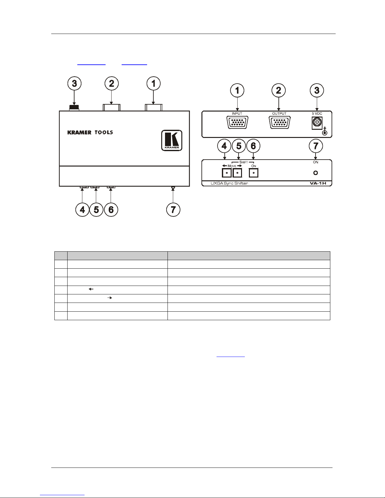
UsethesuppliedDCpowersupplytofeedpowertothemachine.
Pleaseuse recommendedinterconnection cablestoconnectthe machinetoother components.
IF reattached, removed or otherwise interfered with.
*FCCandCEapprovedusingSTPcable(fortwistedpairproducts)
NOTE:
Part1:

Kramer Electronics, Ltd.
Web site: www.kramerelectronics.com
E-mail: info@kramerel.com
P/N: 2900-000687 REV 1
For the latest information on our products and a list of Kramer
distributors, visit our Web site: www.kramerelectronics.com
where updates to this user manual may be found.
We welcome your questions, comments and feedback.
Caution
Safety Warning:
Disconnect the unit from the power supply before
opening/servicing.
Table of contents
Other Kramer Accessories manuals

Kramer
Kramer TBUS-1 User manual

Kramer
Kramer TBUS-3US-22 User manual

Kramer
Kramer FC-5 User manual

Kramer
Kramer FC-29 User manual

Kramer
Kramer RTBUS-4C User manual

Kramer
Kramer RTBUS-11 User manual

Kramer
Kramer TBUS-2 User manual

Kramer
Kramer WAV-5 User manual

Kramer
Kramer PIP-200 User manual

Kramer
Kramer Cobra RWM User manual

Kramer
Kramer KRT-3 User manual

Kramer
Kramer TBUS-204 User manual

Kramer
Kramer UTBUS-2XL User manual

Kramer
Kramer VIAPad User manual

Kramer
Kramer VP-111K User manual

Kramer
Kramer VP-100A User manual

Kramer
Kramer FC-46xl User manual

Kramer
Kramer TOOLS VP-102xl User manual

Kramer
Kramer WAS-3 User manual

Kramer
Kramer WP-500 User manual