Table of Contents
Safety
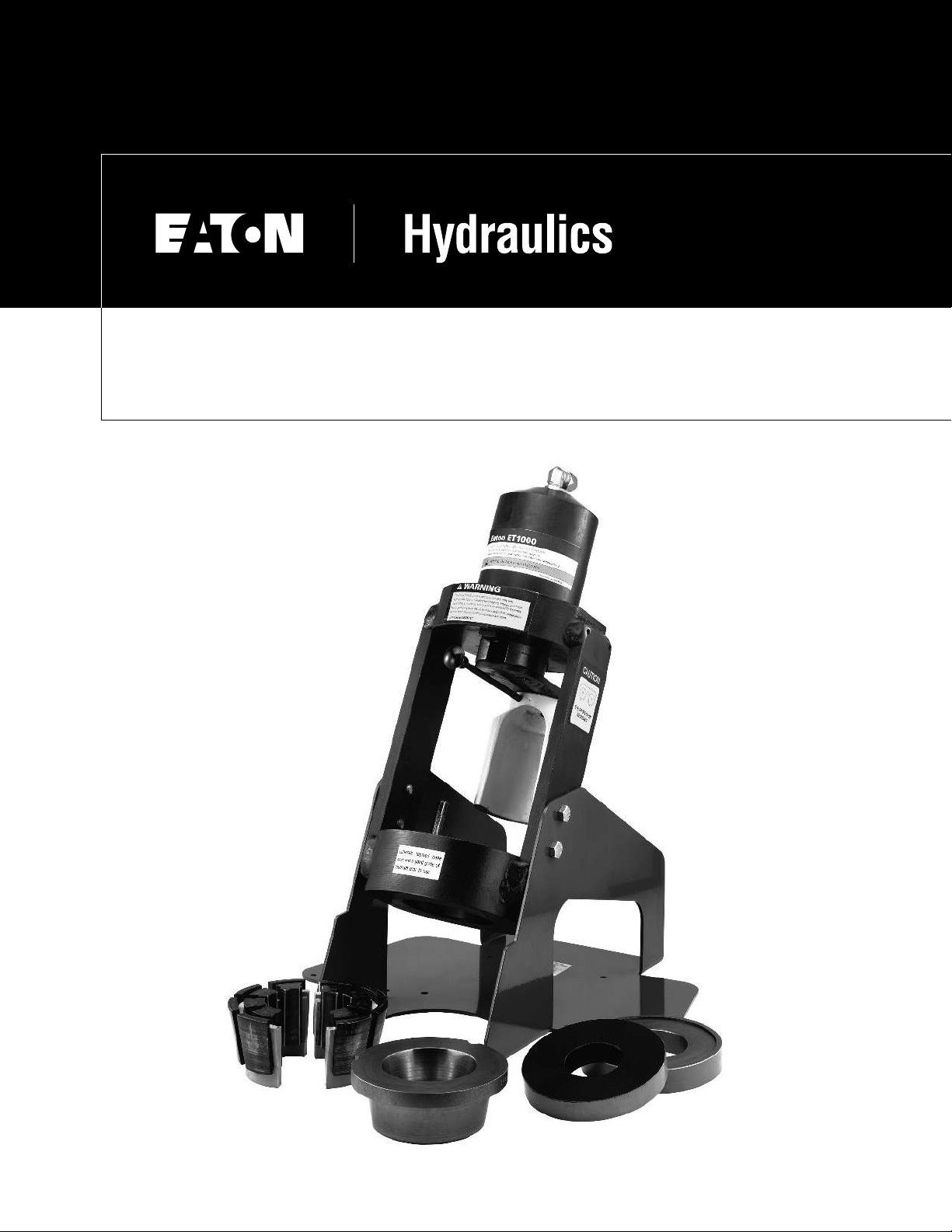
Instructions
2EATON Hydraulics ET1000 Operator’s Manual E-EQCR-TM001-E September 2003
Safety Instructions . . . . . . . . . . . . . . . . . . . . . . . . . . . . . . . . . . . . . . . . . . . . . . . . . . . . . . . . . . . . . . . . . . . . . . . . . . . . . . . . . . . . . . .2
Specifications . . . . . . . . . . . . . . . . . . . . . . . . . . . . . . . . . . . . . . . . . . . . . . . . . . . . . . . . . . . . . . . . . . . . . . . . . . . . . . . . . . . . . . . . . . .3
Accessories . . . . . . . . . . . . . . . . . . . . . . . . . . . . . . . . . . . . . . . . . . . . . . . . . . . . . . . . . . . . . . . . . . . . . . . . . . . . . . . . . . . . . . . . . . . . .3
Set-up and Assembly . . . . . . . . . . . . . . . . . . . . . . . . . . . . . . . . . . . . . . . . . . . . . . . . . . . . . . . . . . . . . . . . . . . . . . . . . . . . . . . . . . . . .3
Operating Instructions
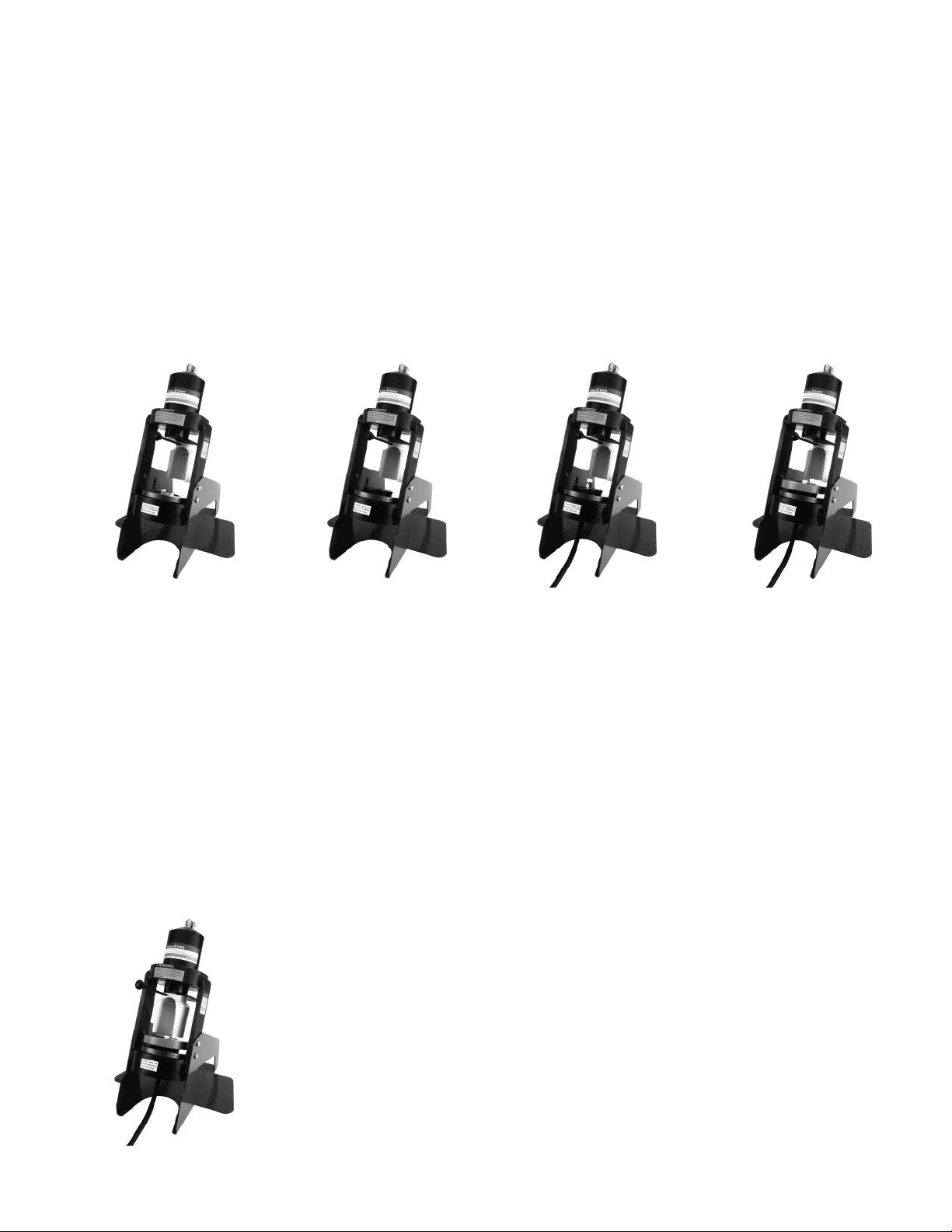
Description of Components . . . . . . . . . . . . . . . . . . . . . . . . . . . . . . . . . . . . . . . . . . . . . . . . . . . . . . . . . . . . . . . . . . . . . . . . .4
Crimping Procedures (large collets) . . . . . . . . . . . . . . . . . . . . . . . . . . . . . . . . . . . . . . . . . . . . . . . . . . . . . . . . . . . . . . . . . .4
Crimping Procedures (small collets) . . . . . . . . . . . . . . . . . . . . . . . . . . . . . . . . . . . . . . . . . . . . . . . . . . . . . . . . . . . . . . . . . .5
Maintenance
Maintenance Intervals . . . . . . . . . . . . . . . . . . . . . . . . . . . . . . . . . . . . . . . . . . . . . . . . . . . . . . . . . . . . . . . . . . . . . . . . . . . . . .6
Machine Maintenance Procedures . . . . . . . . . . . . . . . . . . . . . . . . . . . . . . . . . . . . . . . . . . . . . . . . . . . . . . . . . . . . . . . . . . ..6
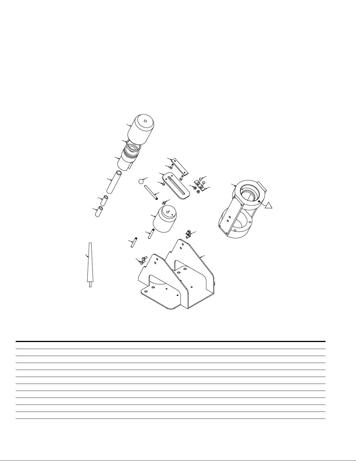
Crimp Machine Components . . . . . . . . . . . . . . . . . . . . . . . . . . . . . . . . . . . . . . . . . . . . . . . . . . . . . . . . . . . . . . . . . . . . . . . . . . . . . . .7
Read and understand the
operator’s manual before
attempting to operate any
equipment.
WARNING
Aeroquip hose, hose fit-
tings and assembly equip-
ment should be used only
with other Aeroquip hose,
hose fittings and assembly
equipment and Weatherhead
hose, hose fittings and
assembly equipment should
be used only with
Weatherhead hose, hose fit-
tings and assembly equip-
ment. Do not combine or use
Aeroquip or Weatherhead
hose, hose fittings and
assembly equipment with
each other, i.e. Aeroquip hose
with Weatherhead fittings, or
with hose, hose fittings or
assembly equipment supplied
by another manufacturer.
Eaton hereby disclaims any
obligation or liability (including
incidental and consequential
damages) arising from breach
or contract, warranty, or tort
(under negligence or strict lia-
bility theories) should
Aeroquip or Weatherhead
hose fittings or assembly
equipment be used inter-
changeably or with any
hose, fittings or assembly
equipment supplied by anoth-
er manufacturer, or in the
event that product instruc-
tions for each specified hose
assembly are not followed.
WARNING
Failure to follow
process and product instruc-
tions and limitations could
lead to premature hose
assembly failures, resulting in
property damage, serious
injury or death.
Aeroquip and Weatherhead
fitting tolerances are engi-
neered to match Aeroquip
and Weatherhead hose toler-
ances. The combination or
use of Aeroquip or
Weatherhead hose and hose
fittings with each other, i.e.
Aeroquip hose with
Weatherhead fittings, or with
hose or fittings supplied by
another manufacturer may
result in the production of
unreliable and/or unsafe hose
assemblies and is neither rec-
ommended nor authorized by
Eaton.
Safety Instructions
1. PREVENT UNAUTHORIZED
OPERATION. Do not per-
mit anyone to operate this
equipment unless they
have read and thoroughly
understand this manual.
2. WEAR SAFETY GLASSES.
3. AVOID PINCH POINTS.
Do not rest your hand on
the crimp ring. Keep your
hands clear of all moving
parts. Do not allow anyone,
other than the operator,
close to the equipment
while it is in operation.
4. MAINTAIN DIES WITH
CARE. Dies used in the
ET1000 crimp machine are
hardened steel, offering
the best combination of
strength and wear resist-
ance for long life.
Hardened dies are general-
ly brittle and care should
be taken to avoid any
sharp impact. Never strike
a die with a hardened
instrument.
5. USE ONLY SPECIFIED
AEROQUIP/WEATHER-
HEAD PRODUCTS. Make
hose assemblies using only
Aeroquip and Weatherhead
hose and fittings specified
for this assembly equip-
ment.
6. VERIFY CORRECT CRIMP
DIAMETERS. Check and
verify correct crimp diame-
ters of all fittings after
crimping. Do not put any
hose assemblies into serv-
ice if the crimp diameters
do not meet Eaton crimp
specifications.
7. Make sure all dies are com-
pletely in place, the spacer
ring rests against the place-
ment pins, and the pusher
is pulled forward into the
detent position before
crimping.
8. DO NOT OVER PRESUR-
IZE. Do not exceed the
10,000 psi hydraulic pres-
sure supplied to the
machine.
NOTE: All components used
to connect the pump and
crimp cylinder must meet the
criteria set forth in the
Material Handling Institute
Specification #IJ100 for
hydraulic jacking applications.
9. DIE CHANGE. DO NOT
INSERT/REMOVE DIES
WHILE THE POWER IS
ON OR MACHINE IS IN
OPERATION.
10. SECURE THE EQUIP-
MENT TO A STABLE
WORK SURFACE. Prior to
operation, secure the crimp
machine to a stable work
surface to prevent the
equipment from tipping.
11. UNPLUG THE POWER
SUPPLY WHEN NOT IN
USE.
12. KEEP WORK AREA
CLEAN. Cluttered areas
and benches invite acci-
dents.