manuals.online logo
Brands
  1. Home
  2. •
  3. Brands
  4. •
  5. Eaton
  6. •
  7. Floodlight
  8. •
  9. Eaton Crouse-Hinds Champ FMV 1000 Series Setup guide

Eaton Crouse-Hinds Champ FMV 1000 Series Setup guide

APPLICATION
FMV 1000 Series Floodlights are suitable for use in the following hazardous
(classified) locations as defined by the National Electrical Code (NEC®):
• Class I, Division 2, Groups A, B, C D
• Class I, Zone 2, AEx nR (AEx nA nR with outlet box), Group IIC
• Wet Locations
• IP56
This luminaire is a restricted breathing product. Restricted breathing, identified
by the marking nR, means that an enclosure is sufficiently well sealed to limit the
entry of flammable gas.
The Champ®FMV 1000 Series comes standard as a “restricted breathing”
luminaire. That means it restricts vapors and gases from entering inside the
luminaire. Therefore, please retain and use the sealing cord connector (located
on the bottom near trunnion mount of the luminaire) with 16-3 type SOW or equal
cord.
Refer to the floodlight nameplate for specific classification information, maximum
ambient temperature suitability, and corresponding operating temperature
(T-Number).
Champ®FMV 1000 Series Floodlight is designed for use indoors and outdoors
in industrial locations where moisture, dirt, corrosion, vibration, and rough usage
may be present. Typical applications include process areas, storage areas, loading
docks, rail yards, building perimeters, parking areas, sports applications, etc.
Champ® FMV 1000 Series Floodlights are trunnion mounted and provided with a
choice of voltages for the following light sources and wattages:
• 1000W High Pressure Sodium (HPS)
• 1000W Metal Halide (MH)
IF 1515 • 10/14 Copyright © 2014, Eaton’s Crouse-Hinds Business Page 1
Champ®High Wattage Floodlight - 1000 Watts
Installation & Maintenance Information
SAVE THESE INSTRUCTIONS FOR FUTURE REFERENCE
IF 1515
WARNING
To avoid electric shock:
• Be certain power is OFF before and during installation and maintenance.
• Fixture must be supplied by a wiring system with an equipment grounding
conductor.
To avoid decreased lamp and fixture life, as well as risk of ignition:
• Use only lamp type and wattage specified on nameplate of fixture.
• Keep tightly closed when in operation.
• Do not position the fixture beyond the aiming range limits.
To avoid burning hands:
While performing maintenance, make sure lens and lamp are cool.
WARNING
To avoid the risk of fire and electric shock, this product should be installed by
a qualified electrician only.
Read and follow these instructions carefully for installation and maintenance to
achieve optimum performance.
WARNING
To avoid explosion:
Make sure the supply voltage is the same as the floodlight voltage.
Do not install where the marked operating temperatures exceed the ignition
temperature of the hazardous atmosphere.
Do not operate in ambient temperatures above those indicated on the floodlight
nameplate.
Do not position the floodlight beyond the aiming range limits depicted on page
2.
Use only the lamp and wattage specified on the floodlight nameplate.
Use proper supply wiring as specified on the floodlight nameplate.
All gasket seals must be clean.
Before opening, electrical power to the floodlight must be turned off. Keep
tightly closed when in operation.
To maintain restricted breathing properties, do not substitute cable fitting
supplied with fixture.
Figure 1
IF 1515 • 10/14 Copyright © 2014, Eaton’s Crouse-Hinds Business Page 2
FLOODLIGHT INSTALLATION
A) Yoke (Trunnion Mount)
1. Using trunnion arm as a template, mark and drill desired location on mounting
surface using only the mounting holes.
2. Secure trunnion arm to mounting surface using 1/2” bolts or lag screws
(provided by installer).
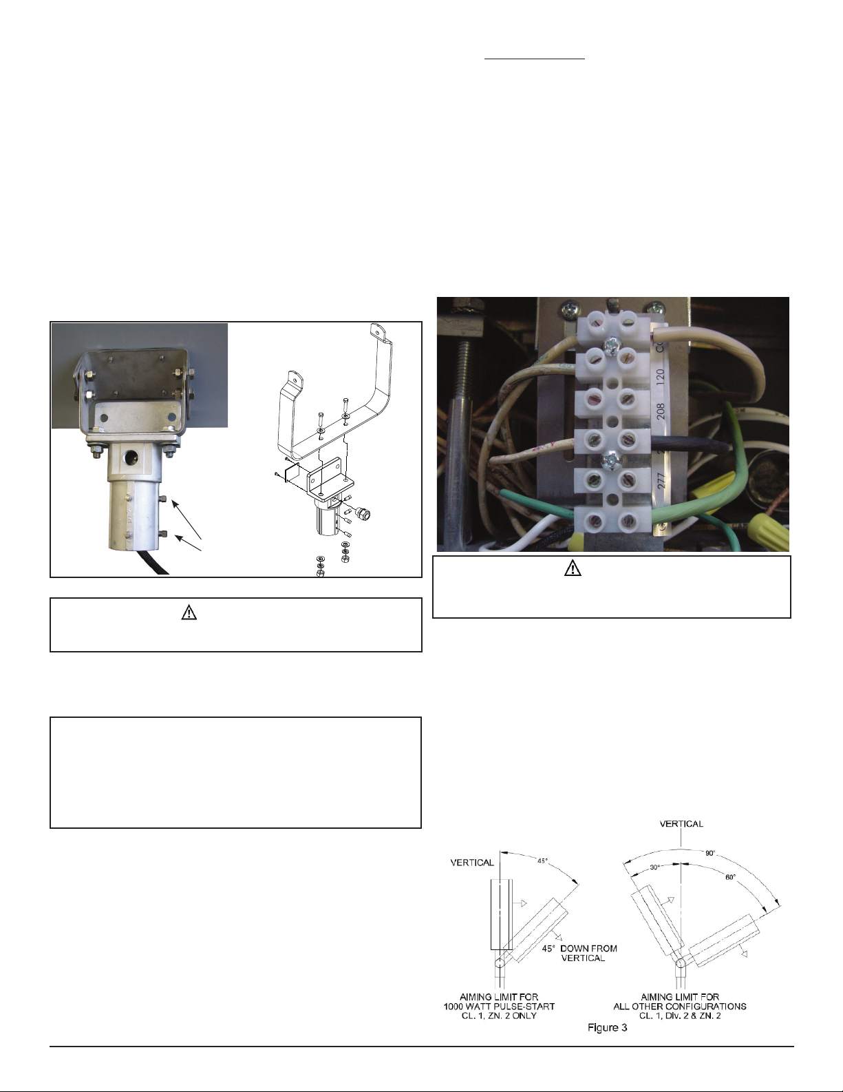
3. To make final vertical adjustment, loosen pivot bolts (2) on floodlight yoke and
position to desired vertical angle. Check to make sure the vertical angle is
within the aiming range shown (see Figure 3). Securely tighten both pivot bolts.
B) Pole Mount with SFA6 Slipfitter
1. Using the bolts, nuts, and lock washers provided, securely fasten the floodlight
yoke to the flange on the SFA6 slipfitter. Refer to Figure 2. Torque the bolts to
45 lbs.-ft.
NOTE: Angular positioning of the floodlight will be done later.
2. Place the SFA6 slipfitter adapter with the secured floodlight onto the 2” pole top
tenon.
3. Secure by tightening the slipfitter base bolts. Torque base bolts to 19 lbs.-ft.
WIRING
A) Pole and Yoke Mount – F2MV, FMV, FMV1000 Series Floodlights
and Champ®voyager nR Series Stainless Steel Floodlight
1. For yoke mount with SFA6 Slipfitter Adapter: Remove the access cover by
loosening the two (2) self-tapping screws. Set aside for reassembly later.
2. Using access opening, pull #16-3 type SO cord (or other extra hard usage
portable cord) supply wire from customer supplied wire chamber through pole.
Using the NCG7575 cable connector provided, position a minimum overall
length of 3 ft. cord for final connection to light fixture. Use a small amount
of HTL thread lubricant when installing cord connector and install according
to instructions supplied with connector. Securely tighten cord connector into
slipfitter.
3. Strip cord insulation jacket back 3 inches and strip each conductor 3/8”.
4. Secure the access cover as follows: For SFA6 slipfitter, secure cover by
tightening the two (2) self-tapping screws against SFA body. For SFA6 SS
slipfitter, attach access plate with four (4) screws and lock washers.
Proceed to B) Wiring the Floodlight.
B) Wiring the Floodlight
1. Loosen the twelve (12) captive floodlight cover screws on the door and
completely open the cover. Remove the four (4) screws that secure the
cover plate over the ballast housing. Be sure to retain the screws in a safe
place.
2. Ensure that line power is not connected to the SOW cord. Strip 3/8” of the
wires of the SOW cord for termination. Notice that all components in the
ballast assembly area are prewired. You will only need to wire line power to
the terminal block and ground wire.
3. Loosen the screws on the terminal block for the appropriate line voltage,
ground (GND), and common (COM) connections. Run the SOW cord
through the sealing cord connector, which is the connector on the bottom
of the luminaire. Terminate the equipment grounding conductor (green) of
the SOW cord first, the common (usually white), and finally the line voltage
(usually black) to the marked terminal blocks.
4. Tighten the sealing cord connector around the SOW cord so that the cord is
held securely in place. Place the ballast assembly cover back over the ballast
assembly area and fasten in place with the four (4) screws.
5. Install the lamp as specified on the nameplate. See LAMP INSTALLATION
AND REPLACEMENT section.
6. Close floodlight cover door making sure that all wires are safely inside and
positioned away from the ballast area. Securely tighten all cover screws. For
proper gasket seal, torque the cover screws to 22 lbs.-in.
7. To make final vertical adjustment, loosen the two (2) pivot bolts on the
floodlight yoke to position floodlight at the desired angle (within the
acceptable aiming range limits). See Figure 3. Tighten the two (2) pivot bolts
to 45 lbs.-ft.
WARNING
To avoid decreased lamp and fixture life or overheating of fixture, do not
position fixture beyond aiming range limits.
WARNING
To avoid explosion: On ballasts with multiple supply voltage taps (MT, TT,
etc.), all unused leads must terminate at the terminal block or be capped with
closed end wire connectors.
Figure 2 - SFA6
Base
Bolts (4)
Under no circumstances may wire splices be used in the slipfitter or pole. Use
continuous length supply cord from fixture to approved customer supplied wiring
chamber.
Note: For Class I, Zone 2 refer to NEC 505.15(c) or for Class I, Division 2,
501.10(b). Wiring must be installed in accordance with NEC 400.14.
IMPORTANT!
8. To make the final horizontal (radial) adjustment, loosen the four (4) slipfitter
base bolts.
9. Rotate the floodlight housing to the desired position.
10. Tighten the slipfitter base bolts to 19 lbs.-ft. to lock in position.
11. Turn power on.
LAMP INSTALLATION AND REPLACEMENT
1. Note both vertical and radial aiming angles. If these are disturbed during
relamping, they should be readjusted after relamping.
2. Disconnect power to the floodlight and allow to cool completely. Allow the
capacitor to discharge for 15 minutes.
3. Completely loosen the twelve (12) captive cover screws and swing open the
cover. See Figure 4.
4. Remove lamp.
5. Perform cleaning and inspection as noted in the MAINTENANCE section.
6. Screw new lamp into lampholder and securely tighten lamp. New lamp must
be identical type, size, and wattage as marked on the floodlight nameplate.
7. Thoroughly clean lens and cover gasket seal with a clean, damp cloth. If this
is not sufficient, use a mild soap or a liquid cleaner such as Collinite NCF or
Duco #7. Do not use an abrasive, strong alkaline, or acid cleaner. Damage
may result.
8. Close floodlight cover door making sure that all wires are safely inside and
positioned away from the ballast area. Securely tighten all cover screws. For
proper gasket seal, torque the cover screws to 22 lbs.-in.
MAINTENANCE
Perform visual, electrical, and mechanical inspections on a regular basis. This
should be determined by the environment and frequency of use. However, it
is recommended that checks be made at least once a year. We recommend
an Electrical Preventive Maintenance Program as described in the National Fire
Protection Association Bulletin NFPA No. 70B. The lens should be cleaned
periodically to ensure continued lighting performance. To clean, wipe the lens with
a clean, damp, soft cloth. If this is not sufficient, use a mild soap or a liquid cleaner
such as Collinite NCF or Duco #7. DO NOT use an abrasive, strong alkaline or acid
cleaner.
• Relamp high pressure sodium fixtures as soon as possible after the lamp
burns out to prevent damage to the ballast.
• Visually check for undue heating evidenced by discoloration of wires or other
components, damaged parts, or leakage evidenced by water or corrosion
in the interior. Replace all damaged or malfunctioning components before
putting the fixture back into service.
• Electrically check to make sure that all connections are clean and tight.
• Mechanically check that all parts are properly assembled.
WIRING DIAGRAMS
WARNING
To avoid ignition of the hazardous atmospheres or overheating of the
floodlight:
Do not position the floodlight beyond the aiming range limits.
Figure 4 - Swing Open Cover with Lift-Off Door
CAUTION
To prevent ballast damage on high pressure sodium floodlights, replace
burned out lamps as soon as possible.
To avoid shortened lamp life, lampholder failure, wiring faults, or
ballast failure, tighten lamp firmly and completely.
To avoid injury, guard against lamp breakage.
WARNING
Luminaire must be de-energized during lamp installation and replacement.
All statements, technical information and recommendations contained herein are based on information and tests we believe to be reliable. The
accuracy or completeness thereof are not guaranteed. In accordance with Crouse-Hinds “Terms and Conditions of Sale,” and since conditions of use
are outside our control, the purchaser should determine the suitability of the product for the intended use and assumes all risk and liability whatsoever
in connection therewith.
Eaton’s Crouse-Hinds Business IF 1515
1201 Wolf Street Syracuse, New York 13208 Revision 5
Copyright © 2014 Revised 10/14
Supersedes 08/99
TERMINAL
BLOCK
LINE V
COM
LINE V
BALLAST
LINE V
LINE V
COM
LAMP
GRN
CAP
X1X3
IGNITOR
X2
WHT
LAMP
BLK
HIGH PRESSURE SODIUM (HPS)
LINE V
COM
LINE V
BALLAST
LINE V
LINE V
COM
LAMP
METAL HALIDE (MH)
TERMINAL
BLOCK
GRN
CAP
WHT
LAMP
BLK
PULSE START METAL HALIDE (MH)

Other Eaton Floodlight manuals

Eaton HALO Home User manual

Eaton

Eaton HALO Home User manual

Eaton Lumark LFS1L30WPCI User manual

Eaton

Eaton Lumark LFS1L30WPCI User manual

Eaton CROUSE-HINDS Champ NPFMA20L Setup guide

Eaton

Eaton CROUSE-HINDS Champ NPFMA20L Setup guide

Eaton Ex-Lite N User manual

Eaton

Eaton Ex-Lite N User manual

Eaton Crouse-hinds series Setup guide

Eaton

Eaton Crouse-hinds series Setup guide

Eaton NFMVA20L Setup guide

Eaton

Eaton NFMVA20L Setup guide

Eaton Crouse-hinds series Setup guide

Eaton

Eaton Crouse-hinds series Setup guide

Eaton Crouse-Hinds FMV Series Setup guide

Eaton

Eaton Crouse-Hinds FMV Series Setup guide

Eaton Lumark TCR Series User manual

Eaton

Eaton Lumark TCR Series User manual

Eaton All-Pro Revolve REV32735M User manual

Eaton

Eaton All-Pro Revolve REV32735M User manual

Eaton HALO FSS153TB User manual

Eaton

Eaton HALO FSS153TB User manual

Eaton Halo Home MST20C User manual

Eaton

Eaton Halo Home MST20C User manual

Eaton Crouse-hinds series Setup guide

Eaton

Eaton Crouse-hinds series Setup guide

Eaton 62624 User manual

Eaton

Eaton 62624 User manual

Eaton All-Pro MS276RD User manual

Eaton

Eaton All-Pro MS276RD User manual

Eaton All-Pro MST1301LW User manual

Eaton

Eaton All-Pro MST1301LW User manual

Eaton HALO HOME FTS20CW User manual

Eaton

Eaton HALO HOME FTS20CW User manual

Eaton Crouse-hinds series Setup guide

Eaton

Eaton Crouse-hinds series Setup guide

Eaton Aethon Manual

Eaton

Eaton Aethon Manual

Eaton Lumark LFD2L30W User manual

Eaton

Eaton Lumark LFD2L30W User manual

Eaton NFFLD-L User manual

Eaton

Eaton NFFLD-L User manual

Eaton Halo MST18VCW User manual

Eaton

Eaton Halo MST18VCW User manual

Eaton CROUSE-HINDS Champ PFM Series Setup guide

Eaton

Eaton CROUSE-HINDS Champ PFM Series Setup guide

Eaton Crouse-Hinds nPFM Series Setup guide

Eaton

Eaton Crouse-Hinds nPFM Series Setup guide

Popular Floodlight manuals by other brands

Fiilex P360 GEen II Series user manual

Fiilex

Fiilex P360 GEen II Series user manual

OmniSistem onyxpro 75 user manual

OmniSistem

OmniSistem onyxpro 75 user manual

Eterna FLEDB10S installation instructions

Eterna

Eterna FLEDB10S installation instructions

CLARIUS EP PLUS IEP-810 installation guide

CLARIUS

CLARIUS EP PLUS IEP-810 installation guide

Sun Power PowerLed FLEX-PIR Series instructions

Sun Power

Sun Power PowerLed FLEX-PIR Series instructions

FEST SYSLITE DUO Original operating manual

FEST

FEST SYSLITE DUO Original operating manual

LI-TIAN LIGHTING LT-ALP-20W-MA installation instructions

LI-TIAN LIGHTING

LI-TIAN LIGHTING LT-ALP-20W-MA installation instructions

Abtech IOM-ALPHA ALP150SH Installation, operation and maintenance instructions

Abtech

Abtech IOM-ALPHA ALP150SH Installation, operation and maintenance instructions

NVC ODESSA V2 instructions

NVC

NVC ODESSA V2 instructions

ORACLE LIGHTING OFL-102-LED instructions

ORACLE LIGHTING

ORACLE LIGHTING OFL-102-LED instructions

Wild tech inferno user guide

Wild tech

Wild tech inferno user guide

ESL HOLF Series installation guide

ESL

ESL HOLF Series installation guide

Perel LEDA500xxW Series user manual

Perel

Perel LEDA500xxW Series user manual

Brilum ADVIVE PLUS Series Installation and operating manual

Brilum

Brilum ADVIVE PLUS Series Installation and operating manual

Francis Searchlights FB230 User instruction & installation manual

Francis Searchlights

Francis Searchlights FB230 User instruction & installation manual

Bunker Hill Security LED-SOLAR Owner's manual & safety instructions

Bunker Hill Security

Bunker Hill Security LED-SOLAR Owner's manual & safety instructions

Utilitech Motion Sensing Security Light UT-9250-BZ owner's manual

Utilitech

Utilitech Motion Sensing Security Light UT-9250-BZ owner's manual

Raytec Spartan Series installation guide

Raytec

Raytec Spartan Series installation guide

manuals.online logo
manuals.online logoBrands
  • About & Mission
  • Contact us
  • Privacy Policy
  • Terms and Conditions

Copyright 2025 Manuals.Online. All Rights Reserved.