GENERAL INFORMATION EATON
2075
This manual has been organized to allow the new user
of the Eaton 2075 to quickly and easily begin test
operations. Read Section
1
to obtain a familiarity with
the test instrument.Follow the proceduresof Section 2
for installation.
The Eaton 2075 can be used in any of 6 test
configurations, depending on the desired test
application. Section
3
is organized to quickly bring the
user to the correct test configuration and its
procedure. Figure 3-1 and Table
3-1
may
be
studied to
obtain a familiarity with the controls and indicators.
Paragraph
3-10
and Table 3-4 guide the user in
selecting the correct test configuration. Paragraphs
3-
11 through 3-18 are the procedures to be used with
each configuration. Each procedure includes the
keystroke sequences necessary for each step. The
remaining pages of Section
3
cover, in greater detail,
specific subjects relevant to operation of the 2075.
Section4 coversoperationwhen the 2075 is controlled
by an external computer via a General Purpose
Interface Bus.
Section
5
includes information and procedures used to
verify that the 2075 is performing correctly.
1-2.
INTRODUCTION
This section of the manual contains a general
description of the Eaton 2075 Noise-Gain Analyzer
including: purpose and function, equipment
requirements, available options, specifications, and
safety precautions.
1-3.
PURPOSE AND USE OF EQUIPMENT
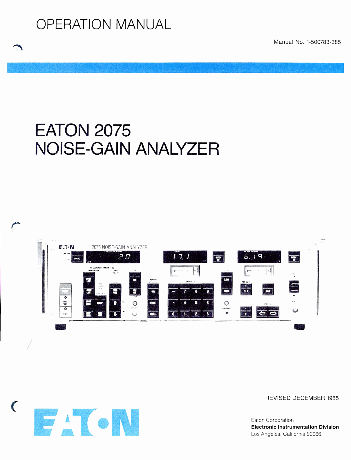
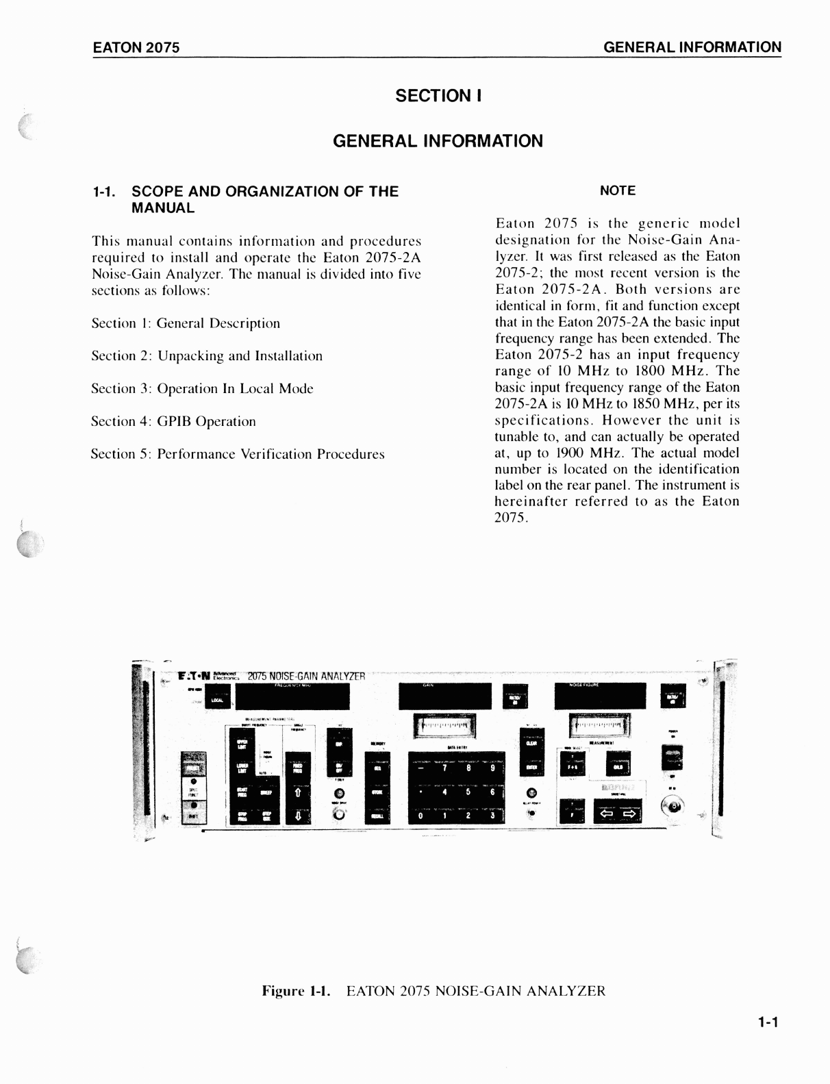
The 2075 Noise-Gain Analyzer is a programmable,
microprocessor-controlled instrument designed
specifically to make precise measurements of noise
and gain characteristics of RF devices. The analyzer
can be controlled in its local mode using its front panel
controls, or in the remote mode, by an external
controller via an IEEE-488 GPIB (General Purpose
Interface Bus).
The analyzer can make the following measurenlents:
e
Corrected Noise Figure and Gain
(F
+
G)*
Uncorrected Noise Figure
(F)
*
Corrected Effective Input Noise
Temperature and Gain (T,
+
G)
Effective Input Noise Temperature (T,)
Corrected Effective Operating Noise
Temperature and Gain (Top
+
G)
Effective Operating Noise Temperature (Top)
Noise Measure (includes Gain) (M)*
Y
Factor
Power
(Y)*
(PWR dB)*
Excess Noise Ratio (ENR)*
*Can be displayed in dB or as a dimensionless ratio
The specified input frequency range of the 2075
extendsfrom 10 MHz to 1850MHz. However, the unit
is actually tunable and operable to 1900 MHz. In its
simplest test configuration the analyzer will make
measurements of RF devices with output frequencies
in this range. More complex test configurations,
requiring one or two stages of external downconver-
sion, allow measurements of devices with output
frequenciesas high as 65.535 GHz. The 2075 has the
capability for controlling the local oscillator used in
the external downconversion process.
1-4.
CALIBRATIONCYCLE
At six month intervals the Performance Verification
Procedures in Section 5 of this manual should be
performed to ensure the continued optimum
performance of the 2075.
At one year intervals the instrument should be fully
calibrated using the alignment and adjustment
procedures from the maintenance manual. These
procedures should be performed by qualified
personnel experienced
in
calibration and servicing of
electronic instrumentation.
Scans by ArtekMedia © 2008