manuals.online logo
Brands
  1. Home
  2. •
  3. Brands
  4. •
  5. Eaton
  6. •
  7. Security Sensor
  8. •
  9. Eaton MEM Watchman 180 User manual

Eaton MEM Watchman 180 User manual

Eaton Electric Limited
MEM 250 Products
Whitegate, Broadway
Chadder ton
Oldham OL9 9QG
UK
tel: 0161 652 1111
fax: 0161 626 1709
www.mem250.com
250250
Watchman 180 - Advanced Passive Infra Red Detector
Technical sheet no. October 03
•Maximum load: 3500 Watts Tungsten Halogen
or Tungsten at 240V AC or 3200 Watts
Tungsten Halogen or Tungsten at 220V
•Operating Voltage: 220V - 240V AC
•Operating Power: 3 Watts
•Load on Time: Adjustable to 10 sec. - 80 sec. -
3.5 mins - 6 mins - 9 mins - 12 mins - 13.5
mins - 16 mins - 21 mins approx.
•Detection Range: 15m approximately, using
standard target (At 10oC this unit may detect in
excess of 20m. Range target is 77KG/170Ib
person walking at 1ft (31cm) per second
tangentially across the detection area).
Note: Tangentially means moving at 90oC to
detector
•Head on Approach: 10m when mounted at 4m
and tilted forward 10 o or 5m when mounted at
2.5m
•Detection Angle: 180o
•Photocell Inhibit: Adjustable between 30 and
300 Lux—Street lighting switches at
approximately 100 Lux
•Sensitivity: This product can be “sensitivity”
adjusted
•Operating Temp: -20oC to +40oC
•IP Rating: Sealed to IP54
•Min load 15VA if load consists of contactor
only wire suppressor (RS part 210-364) in
parallel with contactor coil.
5o
0o
10o
20o
30o
45o
..
.
..
5o
0o
10o
20o
30o
45o
..
.
..
Plug-in detector head
Back box
Each boxed product contains the following parts:
1 x instruction sheet
1 x grey wall box with fixed terminal block
1 x Watchman 180 PIR switch with pre-wired male
plug-i n connection
2 x screws to affix PIR switch to wall box
3 x screw caps
2 x lens mask
1 x adjustment tool
SITING THE PRODUCT
Do not site product near infra-red heat sources i.e. Exhaust
fans, heating and ventilation ducts, washing on line etc.
1. The product should be mounted at 2.5m from ground
level. If the product is mounted higher, the detection range
will increase but the product will be less sensitive close to
the wall.
15m10m5m
Detection range when walking towards
the units.
M OUN TE D AT 4 m WI T H A 1 0 ° T I LT
MOUNTED AT 2.5m
Detection Pattern when walking across the Area
15m 10m 5m 0 5m 10m 15m
Technical sheet no. October 03Watchman 180 Advanced Passive Infra Red Detector
2. At 2.5m high the product will detect up to a range of 15m in
an arc of 180o . Attention should be taken with regard to
adjacent properties, which could cause spurious detection. A
lens mask is supplied to reduce the detection pattern.
INSTALLATION OF PRODUCT
This product should be installed by a competent electrician.
1. If the product is switching 16 amperes it should be
wired directly to a consumer unit / distribution board
with a 16A MCB or 20A rewirable fuse. Cable size
should be 2.5mm2 for 16amp.
2. Remove screws and disconnect the plug connecting
the detector to the back box. When removing
detector head, latch on plug should be released as
indicated below.
3. Insert top screw into the wall, allowing it to protrude
by approximately 3mm. Hook wall box onto screw
using keyhole slot provided. Mark position of
remaining fixings, remove box and complete fixing.
4. Fix the back box to the wall, ensuring the drain hole
is at the bottom.
5. Cable entries are made to the base of the box, using
the holes provided.
6. Connect circuit wiring to terminal block. See diagram
below.
7. To ensure IP54 waterproofing is maintained, an
approved cable gland must be used for the
appropriate size of cable.
8. Plug-in detector head into back box socket. Secure
detector to back box with screws provided and cover
screws with screw caps. Important Note: In order to
maintain IP54 Specification, ensure product is
mounted at least 13mm above any overhanging wall -
see diagram below.
N N SL1 L
N = Neutral to load
N = Supply Neutral
= Earth Terminal
= Supply to load
= Supply live
L
SL1
wall
detector
13mm above overhanging wall
Detector Head Plug
Press Down
Angle - The head will rotate 450 from either side of centre.
A maximum of 1800 from 2700 can be covered
450
0
450
C4
C3 B4
B3
A4
A3
C2
C1
A1
Technical sheet no. October 03Watchman 180 Advanced Passive Infra Red Detector
SETTING DETECTION AREA
To reduce the range of the product, tilt the detector head
forward. The angle of the tilt is shown on the side of the
product.
Both the range and detection angle can be blanked off by
means of the self adhesive lens masking kit. Cut the
appropriate sectors from the lens mask, to cover the area of
the lens that requires masking.
TEST ING
1. Set the light level (yellow knob) to maximum
(clockwise), and the time (blue knob) to minimum
(anti-clockwise).
2. Move in and out of detection pattern, check the PIR
detector switches load on and then off. Once the
detection area has been set satisfactorily, adjust
the light level (yellow knob) and the time (blue
knob) to the desired levels. For your convenience
optimum settings have been indicated.
3. If the unit does not operate, refer to check list and
fault finding list.
CHECK LIST
1. Check the supply in the detector
2. If testing the unit during daylight, ensure that the
photocell has been adjusted in accordance with
point (1) in ‘Testing’.
3. Check lamp is correctly fitted.
FAULT FINDING LIST
1. The unit will not switch on - Check power is
supplied to the unit. Check the plug-in connection,
from the detector head, is joined correctly. Check
that the bulb fitted to the lamp is not faulty and is
correctly fitted.
2. Unit is detecting at too long a range - Check
mounting height and adjust angle of the unit
downwards to reduce range. Note the unit is
designed to switch at a maximum of 15m with 170lb
(77kg person) walking at 900 to the unit. A motor
vehicle may be detected at a longer range.
Alternatively fit an appropriate lens mask.
Important Note - At 100C this unit may detect in
excess of 20m
A1 A2 A3 A4
B1 B2 B3 B4
C1 C2 C3 C4
900 450 0 450 900
Long Range 6 - 15m
Inner Range 3 - 12m
Short Range 0 - 3m
B1
A2
B2
15m 12m 3m 3m 12m 15m
Plan of Masking Effect
See Diagram 1
Diagram 1
Masked Areas
A3 A4
B3 B4
C3 C4
Diagram 2
Masked Areas
A1 A2 A4
B1 B2 B4
C1 C2 C4
15m
15m
90
45
Diagram 1A Diagram 2A
450
900
Technical sheet no. October 03Watchman 180 Advanced Passive Infra Red Detector
FAULT FINDING LIST CONT INUED
3. Unit switches on for no apparent reason - Check
that the unit is not sited near any air vents or
heating flues. Infra-red patterns are given off by
washing on the line, trees blowing in the wind, high
winds and small animals. Note: To reduce
sensitivity adjust the black adjuster screw, on the
rear of the unit, anti-clockwise.
4. Unit will not switch off - Are you standing in
the detection zone? Whilst you are moving in the
detection area the unit will continue to detect. The
light off time is from the last moment detection is
made. Also refer to point 3.

Other Eaton Security Sensor manuals

Eaton CEAG 6811 LED CGLine+ Service manual

Eaton

Eaton CEAG 6811 LED CGLine+ Service manual

Eaton NexiTech Series User manual

Eaton

Eaton NexiTech Series User manual

Eaton CEAG EURO X LED Service manual

Eaton

Eaton CEAG EURO X LED Service manual

Eaton ALL-PRO MS185DW User manual

Eaton

Eaton ALL-PRO MS185DW User manual

Eaton MAB50R User manual

Eaton

Eaton MAB50R User manual

Eaton MPAD-C-A User manual

Eaton

Eaton MPAD-C-A User manual

Eaton MAP820 Instruction manual

Eaton

Eaton MAP820 Instruction manual

Eaton CWGA-0 Series Manual

Eaton

Eaton CWGA-0 Series Manual

Eaton 2450 Series User manual

Eaton

Eaton 2450 Series User manual

Eaton EF-CBD130 User manual

Eaton

Eaton EF-CBD130 User manual

Eaton COOPER POWER SERIES User manual

Eaton

Eaton COOPER POWER SERIES User manual

Eaton Xanura BSX1 User manual

Eaton

Eaton Xanura BSX1 User manual

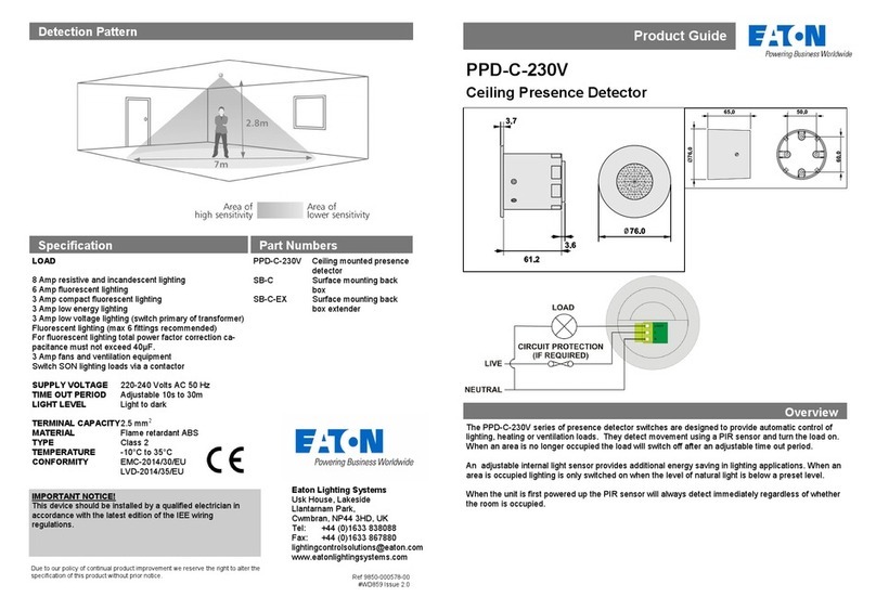
Eaton PPD-C-230V User manual

Eaton

Eaton PPD-C-230V User manual

Eaton Sure-Lites 2C User manual

Eaton

Eaton Sure-Lites 2C User manual
Eaton CWGA-0 Series Manual

Eaton

Eaton CWGA-0 Series Manual

Eaton CEAG Style 22011 CG-S Service manual

Eaton

Eaton CEAG Style 22011 CG-S Service manual

Eaton All-Pro MS180BT User manual

Eaton

Eaton All-Pro MS180BT User manual

Eaton Velos User manual

Eaton

Eaton Velos User manual

Eaton Powerware Series User manual

Eaton

Eaton Powerware Series User manual

Eaton 1450-CSA Manual

Eaton

Eaton 1450-CSA Manual

Eaton xComfort CBMA-02/01 Manual

Eaton

Eaton xComfort CBMA-02/01 Manual

Eaton DET-REXT-PIR30 User manual

Eaton

Eaton DET-REXT-PIR30 User manual
Eaton xComfort CSEZ-01/06 User manual

Eaton

Eaton xComfort CSEZ-01/06 User manual
Eaton Sure-Lites UX6 User manual

Eaton

Eaton Sure-Lites UX6 User manual

Popular Security Sensor manuals by other brands

Hi-Link HLK-LD1125H-24G Applications manual

Hi-Link

Hi-Link HLK-LD1125H-24G Applications manual

Epson USN 52R operating manual

Epson

Epson USN 52R operating manual

HIK VISION DS-PD2-T10AME-EH user manual

HIK VISION

HIK VISION DS-PD2-T10AME-EH user manual

Paradox DG457 Reference and installation manual

Paradox

Paradox DG457 Reference and installation manual

ALCAR SENSOR HEAVY DUTY Mounting instructions

ALCAR

ALCAR SENSOR HEAVY DUTY Mounting instructions

TECHNO-AC SUCCESS ATP-434N operating instructions

TECHNO-AC

TECHNO-AC SUCCESS ATP-434N operating instructions

PROPOINT 8595258 user manual

PROPOINT

PROPOINT 8595258 user manual

Pro-tec Cirrus Pro Series User Manual and Responsibilities

Pro-tec

Pro-tec Cirrus Pro Series User Manual and Responsibilities

smart things SmartSense Motion user guide

smart things

smart things SmartSense Motion user guide

Cool Air LBW-420-LEL user manual

Cool Air

Cool Air LBW-420-LEL user manual

Paradox SR230 installation manual

Paradox

Paradox SR230 installation manual

C.P. Electronics EBDRC-PRM installation guide

C.P. Electronics

C.P. Electronics EBDRC-PRM installation guide

Tinker & Rasor PD Product instructions

Tinker & Rasor

Tinker & Rasor PD Product instructions

Paradox Digigard DG75 instructions

Paradox

Paradox Digigard DG75 instructions

ICON COBALT Pro 101822 quick start guide

ICON

ICON COBALT Pro 101822 quick start guide

GSM Activate IR BEAM manual

GSM Activate

GSM Activate IR BEAM manual

Paradox Magellan PMD1P user manual

Paradox

Paradox Magellan PMD1P user manual

Alarmcom ADC-S40-DC installation guide

Alarmcom

Alarmcom ADC-S40-DC installation guide

manuals.online logo
manuals.online logoBrands
  • About & Mission
  • Contact us
  • Privacy Policy
  • Terms and Conditions

Copyright 2025 Manuals.Online. All Rights Reserved.