manuals.online logo
Brands
  1. Home
  2. •
  3. Brands
  4. •
  5. Eaton
  6. •
  7. Switch
  8. •
  9. Eaton Culter-Hamer CurrentWatch ECSTD Series User manual

Eaton Culter-Hamer CurrentWatch ECSTD Series User manual

IN ORDER TO AVOID ELECTRIC SHOCK OR OTHER POSSIBLE INJURY:
• DO NOT USE THIS PRODUCT FOR HUMAN SAFETY APPLICATIONS.
IT WAS NOT DESIGNED, TESTED OR RECOMMENDED FOR THIS
USE.
• DO NOT USE THIS PRODUCT IN HAZARDOUS LOCATIONS (E.G.
EXPLOSIVE ATMOSPHERES). IT WAS NOT DESIGNED, TESTED OR
RECOMMENDED FOR THIS USE.
• ENSURE THE PRODUCT IS PROPERLY WIRED FOR THE
APPLICATION. REFER TO THE SPECIFICATIONS AND WIRING
DIAGRAMS IN THIS MANUAL.
MODELS COVERED IN THIS MANUAL
Catalog Number Description
ECSTD401SC AC, Solid Core, N.O., 1.5-12, 12-55 or 50-175A Setpoints
ECSTD402SC AC, Solid Core, N.C., 1.5-12, 12-55 or 50-175A Setpoints
ECSTD404SP AC, Split Core, N.O., 2-12, 12-55 or 50-200A Setpoints
ECSTD405SP AC, Split Core, N.C., 2-12, 12-55 or 50-200A Setpoints
ECSTD406SC AC/DC, Solid Core, N.O., 1.5-12, 12-55 or 50-175A Setpoints
ECSTD407SC AC/DC, Solid Core, N.C., 1.5-12, 12-55 or 50-175A Setpoints
ECSTD408SP AC/DC, Split Core, N.O., 2-12, 12-55 or 50-200A Setpoints
ECSTD409SP AC/DC, Split Core, N.C., 2-12, 12-55 or 50-200A Setpoints
INTRODUCTION
The CurrentWatch™ ECSTD
Series are a family of high
performance current-operated
switches with field-adjustable
time delay to help minimize
nuisance trips during start-up
and operation. Designed for
motor status applications where
setpoint accuracy and repeatability are critical, the ECSTD Series offers
a linear setpoint characteristic and constant hysteresis.
Standard features include self-powering, jumper-selectable ranges and
a choice of outputs and housing styles cases. Models are available
which provide N.O. or N.C. AC contacts or solid-state N.O. or N.C.
“universal” contact outputs which can switch AC or DC. Contact action
can be delayed for up to 15 seconds by using the Time Delay Adjust
potentiometer.
Eaton’s current sensor family encompasses a broad range of products
for cost-effective monitoring, status, and predictive maintenance.
Downtime and costly repairs can be avoided by utilizing Eaton’s
products and technologies in your control systems.
To open:
Press tab inward
towards hinge
Important:
Keep contact areas clean
INSTALLATION
Considerations for all ECSTD Series models…
• Run wire to be monitored through the aperture (opening) in the
switch body
• These switches can be located in the same environment as
motors, contactors, heaters, pull-boxes and other electrical
enclosures
• Mounting can be done in any position or hung directly on a wire
with a wire tie
• Be sure to leave at least one inch distance between sensor and
other magnetic devices
Considerations for split-core models only…
• Press the tab in the direction shown below to open the sensor.
• After placing the wire in the aperture, press the hinged portion
firmly downward until a click is heard and the tab pops out fully.
• Keep split-core contact areas clean. Silicon grease is factory
applied on the mating surfaces to prevent rust and improve
performance. Be careful not to allow grit or dirt into the grease in
the contact area, particularly on core mating surfaces of split core
models. Sensor operation could be impaired if mating surfaces do
not have good contact. Check visually before closing.
QUICK INSTALL GUIDE
The below steps can be followed to quickly install a CurrentWatch™
ECSTD Series switch.
1. Run the wire to be monitored through the aperture
2. Mount the sensor
3. Connect output wiring
a. Use up to 14 AWG copper wires
b. Ensure load matches the output shown on the switch label
4. Adjust the setpoint
a. Choose correct range by positioning the range jumper
(removed for low, across two appropriate pins for medium, or
high)
b. Use the potentiometer to adjust the setpoint
P51921 Rev 02
Effective: June 2007 Page 1
Installation Instructions
CurrentWatch™ ECSTD Series AC Current Switches with Time Delay
WARNING
Questions? Call our Sensor Application Engineers at (800) 426-9184.
394000109
P51921 Rev 02
Effective: June 2007 Page 2
Questions? Call our Sensor Application Engineers at (800) 426-9184.
RANGES AND MAXIMUM AMPS
Housing Range
Maximum Amps
Continuous 6 sec. 1 sec.
Solid Core 1.5-175A 150A 400A 1,000A
Split Core 2-200A 150A 400A 1,000A
SWITCHING DELAY
Delay Type Low Range Mid Range High Range
On Delay 0.23 sec. max. 0.05 sec. max. 0.03 sec. max.
Off Delay 0.02 sec. max. 0.02 sec. max. 0.01 sec. max.
TROUBLESHOOTING
Problem Solution
Switch is
always tripped
The setpoint may be too low. Turn pot clock-wise to increase setpoint.
Switch may have been overloaded and contacts are burned out. Check the
output load, remembering to include inrush on inductive loads (coils, motors).
Switch will
not trip
The setpoint may be too high. Turn pot counter-clockwise to decrease
setpoint.
For split core models, the core contact area may be dirty. Open the sensor
and clean the contact area.
The monitored current may be below the minimum required. Loop the
monitored wire several times through the aperture until the “sensed” current
rises above the minimum. The sensed amps equals “actual amps” multiplied
by the “number of loops.” Count loops on the inside of the aperture.
Switch may have been overloaded and contacts are burned out. Check the
output load, remembering to include inrush on inductive loads (coils, motors).
SPECIFICATIONS
Specification Value
Power Supply Self Powered–No Power Supply Needed
Output Magnetically Isolated Solid State Switch
Output Rating AC-Only Models: N.O./N.C. 1A @ 240V AC
AC/DC Models:
N.O. 0.15A @ 240V AC/DC
N.C. 0.20A @ 135V AC/DC
Off-State Leakage ECSTD402SC and ECSTD405SP Models: 2.5 mA
All Other Models: Negligible
Response Time Adjustable, 0.12 to 15 seconds
Setpoint Range Solid Core Models: 1.5-12, 12-55 and 50-175A
Split Core Models: 2-12, 12-55 and 50-200A
Setpoint Adjustment Solid Core Models: 15-Turn Potentiometer
Split Core Models: 4-Turn Potentiometer
Hysteresis Constant 5% of Setpoint
Overload See “Ranges and Maximum Amps” in Above Table
Isolation Voltage UL Listed to 1,270V AC, Tested to 5,000V AC
Frequency Range 50-100Hz
Sensing Aperture Solid Core Models: 0.75 in. (19mm) dia.
Split Core Models: 0.85 in. (21.7mm) sq.
Housing UL94 V0 Flammability Rated
Environmental Operating Temperature: -58 to +149° F (-50 to +65° C)
Humidity: 0-95% RH, Non-Condensing
Approvals UL and ULC Listed (Pending)
CE Certified (Pending)
394000109
SETPOINT ADJUSTMENT
The CurrentWatch™ ECSTD Series setpoint and time delay are adjusted
through two four-turn pots (on split-core models) and 15-turn pots (on
solid-core models). The unit comes from the factory with setpoint and
time delay set to the lowest level (fully counter-clockwise). Turning the
pots clockwise will increase their value. All pots have a slip-clutch to
prevent damage at either end of their rotation. To determine where the
adjustment is, turn the pot all the way counter-clockwise. This will return
it to the minimum setpoint.
Important Setpoint Adjustment Notes
• Output contacts are solid-state. Check output status by applying
the appropriate voltage to the contacts and reading the voltage
drop across the contacts. An Ohmmeter set on “continuity” will
give misleading results.
• It is recommended the setpoint be adjusted to allow for the usual
utility company voltage variations of 10 to 15 percent.
Typical Adjustment Steps
1. Identify expected Input Range and position jumper accordingly.
For LOW range, remove jumper entirely. For MID or HIGH range,
place jumper over proper two pins.
2. Turn the setpoint pot to the minimum value (four turns for split-core
models and fifteen turns for solid-core models).
3. Have normal operating current running through the switch. The
output should be tripped because the pot is at its minimum
setpoint. For units with LED, it should be flashing fast (two to three
times per second).
4. Turn the pot clockwise until the unit un-trips. This is indicated by
the slow flashing of the LED (once every two to three seconds), or
by the changing of the output switch status.
5. Now turn the pot counter-clockwise slowly until the unit trips again.
a. To set underload, turn the pot about 1/8 turn further counter-
clockwise
b. To set overload, turn the pot about 1/8 turn further clockwise
6. Adjust the time delay of the contact action in the same fashion.
Increase time delay by turning the pot clockwise. For split-core
models, each quarter-turn corresponds roughly to one second of
delay time. Expect ten turns for a 15 second delay.
LED INDICATION / OUTPUT STATUS
Monitored Amps
Output Smart-LED
(If Present)N.O. N.C.
None or Minimum Open Closed Off
Below Trip Level Open Closed Slow (2 sec.)
Above Trip Level Closed Open Fast (0.5 sec.)
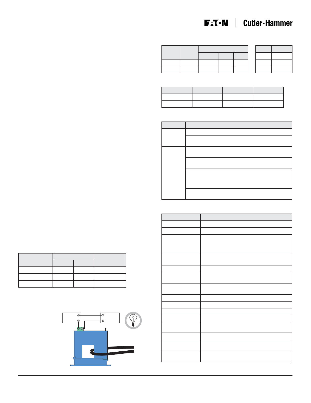
WIRING DIAGRAM
Connect control or monitoring wires to the sensor. Use up to 14 AWG
copper wire and tighten terminals to 5 inch-pounds torque. Be sure the
output load does not
exceed the solid state
output rating.
CAUTION! Incandescent
lamps can have “cold
filament inrush” current of
up to ten times their rated
amperage. Use caution
when switching lamps.
HYSTERESIS
Setting Hysteresis
Low <0.01A
Mid <0.1A
High <0.5A
AC or DC
Power
AC or DC
Load
Output Signal
To Monitored Load
Use caution when
switching lamps

This manual suits for next models

8

Other Eaton Switch manuals

Eaton 10250T Manual

Eaton

Eaton 10250T Manual

Eaton P1 /E Manual

Eaton

Eaton P1 /E Manual

Eaton Bussmann Series User manual

Eaton

Eaton Bussmann Series User manual

Eaton XNH00-1-A160-BT Manual

Eaton

Eaton XNH00-1-A160-BT Manual

Eaton GHG 273 User manual

Eaton

Eaton GHG 273 User manual

Eaton T ST/SVB Series Manual

Eaton

Eaton T ST/SVB Series Manual

Eaton Cutler-Hammer QS4500TE0001 Programming manual

Eaton

Eaton Cutler-Hammer QS4500TE0001 Programming manual

Eaton T3 I2H/RT Series Manual

Eaton

Eaton T3 I2H/RT Series Manual

Eaton ES Series User manual

Eaton

Eaton ES Series User manual

Eaton NHI-E-PKZ0 Series Manual

Eaton

Eaton NHI-E-PKZ0 Series Manual

Eaton TM-1-8210 Series Manual

Eaton

Eaton TM-1-8210 Series Manual

Eaton NZM3-XKR Manual

Eaton

Eaton NZM3-XKR Manual

Eaton AGswitch User manual

Eaton

Eaton AGswitch User manual

Eaton CEMU-01/03 Manual

Eaton

Eaton CEMU-01/03 Manual

Eaton P1-25-I2H-SW Manual

Eaton

Eaton P1-25-I2H-SW Manual

Eaton TRIPP LITE U223-004-IND User manual

Eaton

Eaton TRIPP LITE U223-004-IND User manual

Eaton EGS Series User manual

Eaton

Eaton EGS Series User manual

Eaton RTC-50 User manual

Eaton

Eaton RTC-50 User manual

Eaton BZM1-XA User manual

Eaton

Eaton BZM1-XA User manual

Eaton TRIPP LITE Series User manual

Eaton

Eaton TRIPP LITE Series User manual

Eaton GHG 981 Series User manual

Eaton

Eaton GHG 981 Series User manual

Eaton Pow-R-Line SPX0361126 User manual

Eaton

Eaton Pow-R-Line SPX0361126 User manual

Eaton T6-160-6/V/SVB/HI11 Manual

Eaton

Eaton T6-160-6/V/SVB/HI11 Manual

Eaton XNH00-1-S160 Manual

Eaton

Eaton XNH00-1-S160 Manual

Popular Switch manuals by other brands

NetComm NP2240 quick start guide

NetComm

NetComm NP2240 quick start guide

ZyXEL Communications AES-100 user guide

ZyXEL Communications

ZyXEL Communications AES-100 user guide

ANTAIRA LMX-C602G-SFP-V2 Series Hardware manual

ANTAIRA

ANTAIRA LMX-C602G-SFP-V2 Series Hardware manual

Artel INFINITYLINK ILC205 Installation and operation guide

Artel

Artel INFINITYLINK ILC205 Installation and operation guide

hager HXA031H User instructions

hager

hager HXA031H User instructions

Eterna TLS68EX Safety and installation instructions

Eterna

Eterna TLS68EX Safety and installation instructions

Keysight Technologies 87104A SP4T Operating and service manual

Keysight Technologies

Keysight Technologies 87104A SP4T Operating and service manual

Omron B3F manual

Omron

Omron B3F manual

Siemens 3KF2 F5 3KF3 F5 Series operating instructions

Siemens

Siemens 3KF2 F5 3KF3 F5 Series operating instructions

HP ProCurve 5400zl Series Installation and getting started guide

HP

HP ProCurve 5400zl Series Installation and getting started guide

Acnodes KC801 user manual

Acnodes

Acnodes KC801 user manual

Advantech EKI-7659CI user manual

Advantech

Advantech EKI-7659CI user manual

HP J3245A Installation and configuration guide

HP

HP J3245A Installation and configuration guide

D-Link 5000 Series Cli reference guide

D-Link

D-Link 5000 Series Cli reference guide

Digitus DS-12820 user manual

Digitus

Digitus DS-12820 user manual

Rocktron PatchMate LOOP 8 user manual

Rocktron

Rocktron PatchMate LOOP 8 user manual

H3C S5130-28F-EI Configuration guide

H3C

H3C S5130-28F-EI Configuration guide

ADC FireWire Patch Panel IEEE 1394a Specification sheet

ADC

ADC FireWire Patch Panel IEEE 1394a Specification sheet

manuals.online logo
manuals.online logoBrands
  • About & Mission
  • Contact us
  • Privacy Policy
  • Terms and Conditions

Copyright 2025 Manuals.Online. All Rights Reserved.