2
Technical Data TD00801003E
Effective November 2011
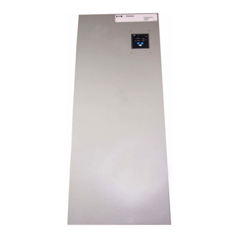
Elevator Control ES Switch
EATON CORPORATION www.eaton.com
Danger and Warnings
DANGER
HAZARDOUS VOLTAGE WILL CAUSE SEVERE INJURY OR DEATH. WORKING
ON OR NEAR ENERGIZED CIRCUITS POSES A SERIOUS RISK OF ELECTRICAL
SHOCK. DE-ENERGIZE ALL CIRCUITS BEFORE INSTALLING OR SERVICING
THIS EQUIPMENT AND FOLLOW ALL PRESCRIBED SAFETY PROCEDURES.
IMPORTANT
THESE PROCEDURES DO NOT CLAIM TO COVER ALL POSSIBLE DETAILS OR
VARIATIONS ENCOUNTERED WITH THE ELEVATOR CONTROL SWITCH ELE-
VATOR DISCONNECT. NOR DO THEY PROVIDE FOR ALL POSSIBLE CONDI-
TIONS THAT MAY BE ENCOUNTERED. IF FURTHER INFORMATION IS
DESIRED OR NEEDED TO ADDRESS ANY PARTICULAR ISSUE NOT COVERED
IN THIS DOCUMENT, CONTACT YOUR EATON REPRESENTATIVE. THE
INFORMATION IN THIS DOCUMENT DOES NOT RELIEVE THE USER FROM
EXERCISING GOOD JUDGMENT, NOR FROM USING SOUND SAFETY PRAC-
TICES.
NOTE: BECAUSE EATON HAS A POLICY OF CONTINUOUS PRODUCT
IMPROVEMENT, WE RESERVE THE RIGHT TO CHANGE DESIGN SPECIFICA-
TIONS WITHOUT NOTICE. SHOULD A CONFLICT ARISE BETWEEN THE GEN-
ERAL INFORMATION IN THIS DOCUMENT AND THE CONTENTS OF DRAW-
INGS OR SUPPLEMENTARY MATERIAL, OR BOTH, THE LATTER SHALL TAKE
PRECEDENCE. FOR THE LATEST VERSION OF THIS INSTRUCTION LEAFLET,
DOWNLOAD TD00801003E FROM THE EATON WEB SITE AT: www.eaton.
com.
THE CONTENTS OF THIS INSTRUCTION LEAFLET ARE NOT PART OF, NOR
DO THEY MODIFY, ANY PRIOR OR EXISTING AGREEMENT, COMMITMENT
OR RELATIONSHIP. THE EATON TERMS AND CONDITIONS OF SALE CON-
STITUTE THE ENTIRE OBLIGATION OF EATON. THE WARRANTY IN THE
TERMS AND CONDITIONS OF SALE IS THE SOLE WARRANTY OF EATON.
ANY STATEMENTS IN THIS DOCUMENT DO NOT CREATE NEW WARRAN-
TIES OR MODIFY ANY EXISTING WARRANTY.
IMPORTANT
FOR THE PURPOSE OF THIS INSTRUCTION LEAFLET, A QUALIFIED PERSON:
(A) IS FAMILIAR WITH THE SUBJECT EQUIPMENT AND THE HAZARDS
INVOLVED WITH THEIR APPLICATION, USE, ADMINISTRATION, AND
MAINTENANCE.
(B) IS TRAINED AND AUTHORIZED TO DE-ENERGIZE, CLEAR, GROUND,
AND TAG CIRCUITS AND EQUIPMENT IN ACCORDANCE WITH
ESTABLISHED SAFETY PRACTICES.
(C) IS TRAINED IN THE PROPER CARE AND USE OF PERSONAL
PROTECTIVE EQUIPMENT SUCH AS RUBBER GLOVES, HARD HAT,
SAFETY GLASSES OR FACE SHIELDS, ARC-FLASH CLOTHING, ETC., IN
ACCORDANCE WITH ESTABLISHED SAFETY PRACTICES.
(D) IS TRAINED TO RENDER FIRST AID.
(E) HAS RECEIVED SAFETY TRAINING TO RECOGNIZE AND AVOID THE
HAZARDS INVOLVED.
(F) AS THE SKILLS AND KNOWLEDGE PERTAINING TO THE
CONSTRUCTION AND OPERATION OF THIS EQUIPMENT AND ITS
INSTALLATION.
Signal Words
The signal words “DANGER,” “WARNING,” “CAUTION” and
“NOTICE” (along with their assigned symbol) throughout this manu-
al indicate the degree of hazard the user may encounter.
These symbols and words are defined as:
DANGER
DANGER: Indicates a hazardous situation which, if not avoided, will
result in death or serious injury.
WARNING
WARNING: Indicates a hazardous situation which, if not avoided,
could result in death or serious injury.
CAUTION
CAUTION: Indicates a hazardous situation which, if not avoided,
could result in minor or moderate injury.
NOTICE
NOTICE: Indicates a hazardous situation which, if not avoided, could
result in property damage.
Safety Concerns
The following are important safety precautions that Elevator Control
Switch elevator disconnect users should observe at all times. This
summary is not comprehensive. It is assumed the Elevator Control
Switch elevator disconnect user will follow standard safety precau-
tions for working in an electrical environment. For more information
on safety precautions and procedures, consult the following sources:
Web Sites:
National Fire Protection Association (NFPA): www.nfpa.org.
Underwriters Laboratories (UL): www.ul.com.
National Electrical Manufacturers Association (NEMA):
www.nema.org.
International Electrotechnical Commission (IEC): www.iec.ch.
