Eaton Resistel FHF1128610102 User manual

Robust, weather-resistant telephone
Operating instructions
FHF BA 9701-22 01/19

2
Foreword
Our explosion-proof, weather-resistant telephone is a captivating
product on account of its precision, convenience, long service life and
reliability. It is freely programmable and the optimum choice for adverse
ambient conditions. Be it seawater, high atmospheric humidity, dust or
the toughest mechanical strains, the weather-resistant telephone
accomplishes its aim in any conditions. The reason for this is the robust
keypad made of stainless steel and an extremely solid housing made of
impact-resistant and shockproof cast-moulding material. All of the
components utilised are even resistant to leeches and lubricants. The
21-component stainless steel keypad – which can be operated by a user
wearing gloves – and the easily readable alphanumeric display as well
as the uncomplicated menus all ensure simple operation – thus fulfilling
the requirements for a leading-edge and operationally reliable means of
communication. As a telephone suitable for connecting to the public
telephone network and to private automatic branch exchanges, the
ExResistTel always ensures reliable connections.
ExResistTel ZB is designed for telephone exchange operation and
corresponds to the ExResistTel, except for keypad and display.

3
Table of contents
General operating instructions ............................................................ 4
Overview of the device........................................................................ 5
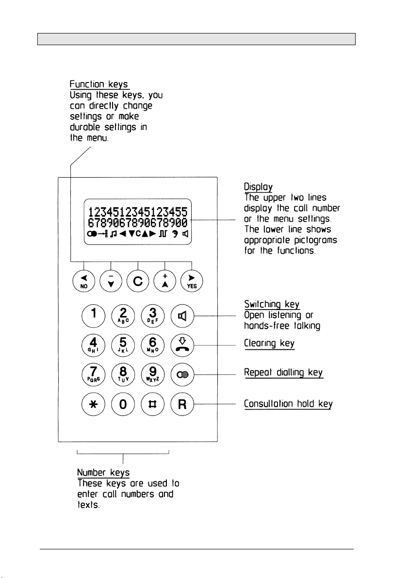
Display and keyboard ......................................................................... 8
Contents after unpacking .................................................................... 9
ZB version notes ................................................................................. 9
Explosion protection – device description ........................................ 10
Characteristic data ........................................................................... 13
Identification ...................................................................................... 14
Assembly and installation ................................................................. 15
Connection diagram .......................................................................... 16
Sling holder ....................................................................................... 16
Drilling diagram ................................................................................. 17
Start-up ............................................................................................. 18
Maintenance...................................................................................... 18
Handset mode................................................................................... 18
Open Listening .................................................................................. 18
Hands-free talking ............................................................................. 18
Working with the headset................................................................. 19
Menu ................................................................................................. 20
Main Menu ........................................................................................ 21
Submenu: Telephone Book .............................................................. 22
Submenu: Change Telephone Book................................................. 23
Submenu: Lock / PIN ........................................................................ 24
Submenu: Settings............................................................................ 25
Submenu: Languages....................................................................... 26
Default Settings................................................................................. 26
Menu overview .................................................................................. 27
Technical data................................................................................... 28
Use in marine and offshore segments ............................................. 31
Service ............................................................................................. 32
Maintenance and servicing ............................................................... 32
Waste disposal.................................................................................. 32
Warning and safety instructions ........................................................ 32
CE symbol......................................................................................... 33
Index of catchwords .......................................................................... 34

4
General operating instructions
1. Both the explosion-proof ExResistTel telephone and the ZB version
are designed for connection to dial ports with analogue connection
points.
2. The handset is fitted with a stray-field coil for connecting hearing-
aids. People who use hearing-aids which have an inductive receiver
can receive the earphone signal directly.
3. The ZB version is not equipped with keypad and display, therefore
not all the features are available with this version.
4. The ExResistTel has a handset module with a dry reed contact as a
hook switch. In order to terminate an existing call connection, the
handset must be hung up. In order to interrupt an existing call
connection, it is sufficient to press the clearing key on the
keypad.(see page 8)
5. Use the menu to program the appropriate settings. To access the
menu, pick up the handset and press the "YES" key.
6. If you take longer than 2 minutes before you begin making a choice,
the power supply of the exchange may be switched off. If that
occurs, you will no longer hear a dialling tone. In that case, please
replace the handset and wait 2 seconds before picking it up again.
7. When a setting is stored successfully, this is confirmed by an
acknowledgement tone.
8. When you receive a call, the ExResistTel rings at the ringer-volume
level selected by you and, for the duration of the calling sound, the
symbols ( ( ( ) ) ) appears on the display.
9. If you enter a PIN with the menu you can restrict or block dial
functions. Forgetting the PIN is the equivalent of losing a key. If you
forget the PIN, please contact our technical support.
10. You have a guarantee period of 24 months commencing from the
date of purchase. If you have a problem, please contact our
technical support in Germany, located in Mülheim an der Ruhr:
Phone: +49 208 82 68 256
Fax: +49 208 82 68 377
e-mail: fhf-support@eaton.com
If a fault occurs which cannot be rectified by telephone, please send
the whole telephone along with a copy of the sales receipt to the
following address:

5
FHF
Support ExResistTel
Gewerbeallee 15-19
D-45478 Mülheim an der Ruhr
Germany
If, on examination of the telephone, it is discovered that a fault is not
the case, you will be charged a service fee.
Overview of the device
Note: In case of the ZB version, the keypad and display are replaced by
a solid metal plate.

6
Overview of the device
Outside view of telephone lower part
Inside view of telephone upper part

7
Overview of the device
Inside view of telephone lower part
Protection Class II – Components
Factory supplied with: plastic cable entry.
Note: The ZB model does not have a display.
Protection Class I – Components
Factory supplied with: M20x1.5 threaded hole or a 1/2” NPT metal adapter for
connecting armoured cables or conduit systems.
Sealing plug
Sealing plug
Programming
interface connector
Keypad ribbon cable
with connector
Display interface
connector
Lower part
of telephone
Screws
Loudspeaker
cable
Reed
switch cable
Sealing plug
Sealing plug
Sealing plug
Sealing plug
Metal adapter
Sealing plug
Cable entry

8
Display and keyboard (except for ZB version)

9
Contents after unpacking
The delivery includes:
- ExResistTel telephone
-Operating instructions ExResistTel
-Operating instructions cable entry (optional)
-EU declaration of conformity (ATEX)
-2 self-adhesive lettering plates
ZB version notes
The ExResistTel / ZB connects – depending on the features of the
PABX – with the PABX while lifting the handset. The ExResistTel / ZB
can be called also, because the ringing circuit is built in.
Furthermore there are interfaces for operating an optional second
earpiece and an optional secondary ringer.
Thus the ZB version offers the following features:
•Establishing a connection by lifting up the receiver
•Ringing by means of integrated ringing device
•Connection of second earpiece
•Connection of secondary ringer

10
Explosion protection – device description
Regarding the explosion protection the ExResistTel telephone and the
ExResistTel telephone in ZB version are identical.
The explosion protection enables the user to make and receive calls
within hazardous areas of zone 1 and zone 21, in presence of an
explosive gas or dust atmosphere.
The ExResistTel telephone is designed for connection with analogue
telephone networks.
The accessories headset, second earpiece and external secondary
ringer are not parts of the ExResistTel telephone, but optional extras.
The housing of the ExResistTel telephone consists of an electro-
statically conductive cast-moulding equipped with a stainless steel
keypad. The keypad front plate contains a display sealed by a viewing
window.
The ZB version comprises no keypad and no display area, but a solid
front plate.
The housing consists of a rectangular lower part, in which there has
been placed a tray for mounting the electronic parts, as well as a
vaulted cover with a keypad.
The cover and the lower part of the housing, divided by a surrounding
seal only, are pressed together by four screws. The cover makes up
both the non-intrinsically safe and the intrinsically safe electrical
enclosure. The electronics circuit board is situated in the tray of the
lower part of the housing, completely embedded in a protective
compound.
Non-intrinsically safe terminals in increased safety:
Protruding from the compound (see connecting diagram on page 16), a
4-pole increased-safety terminal row is intended for connecting the non-
intrinsically safe telephone network (A, B), terminals 13 and 14, as well
for connecting an optional, external, explosion-protected secondary
ringer (Bell shunt1, Bell shunt), terminals 15 and 16.

11
Intrinsically safe terminals:
Protruding from the compound (see connecting diagram on page 16),
a 12-pole intrinsically safe terminal row is intended for connecting the
receiver, which is permanently connected with the telephone housing,
terminals 1 to 4, as well as the intrinsically safe accessories, terminals 5
to 10.
The terminals 7 and 8 are intended for the connection of dynamic
receiver insets, like the ones used in second earpieces and headsets.
This output thus can be used for connecting a second earpiece or a
headset, which means that a second earpiece and a headset cannot be
connected simultaneously.
Terminal
Note
Use
1
Dynamic receiver inset connection 1
Receiver inset
2
Dynamic receiver inset connection 2
3
Electret-foil microphone connection (+)
Receiver
microphone
4
Electret-foil microphone connection (-)
5
Electret-foil microphone connection (+)
Headset
Microphone, not for
ZB version
6
Electret-foil microphone connection (-)
7
Dynamic receiver inset connection 1
Headset or
second earpiece
8
Dynamic receiver inset connection 2
9
Jumper between the terminals 9 and 10
is identified by the telephone as
headset connected.
Headset
10
To connect accessories, you must replace the blind plugs screwed into
the telephone housing by explosion-proof cable glands (M20x1.5).
Before connecting intrinsically safe accessories, and if a system
certificate for the intended connection does not exist, the constructor
should perform an evaluation of the intrinsic safety according to
EN 60079-25.
The technical data for the evaluation of the intrinsic safety can be found
in the chapter “Characteristic data”.
Further information see EN 60079-14.
A metal bracket is supplied for hanging up the intrinsically safe second
earpiece or headset. The metal bracket should be attached to the
telephone by means of the two threaded bushes in the floor of the
telephone housing. The corresponding bores in the metal bracket can

12
be used to screw the bracket securely onto to the housing floor (see
overview of the device on page 6). Thus, if the constructor wants to use
the metal bracket, the first thing he has to do, is to fix it to the housing
floor. Subsequently, the device may be mounted on the wall.
Intrinsically safe programming interface
An 8-pole, intrinsically safe contact strip (14)(see overview of the device
on page 7) protrudes from the compound. This contact strip is
exclusively used by the manufacturer for programming purposes. Do not
switch any circuits by using the contact strip. The constructor may not
perform any kind of programming.
Intrinsically safe display interface
An 8-pole, intrinsically safe contact strip with a soldered-on circuit board
(15) (see overview of the device on page 7) protrudes from the
compound. The circuit board is equipped with a zero power plug for
connecting the intrinsically safe LC display film conductor. Connect the
built-in display only to this interface.
Intrinsically safe strand connection to the built-in loudspeaker
An intrinsically safe 2-pole strand conductor (16) (see overview of the
device on page ) goes from the compound to the built-in loudspeaker.
The strand is soldered onto the circuit board below the compound, as
well as onto the loudspeaker.
Intrinsically safe strand connection to the reed switch
An intrinsically safe, 2-pole strand conductor (17) goes from the
compound to a circuit board with a reed switch (see overview of the
device on page 7). On the compound-covered circuit board the strand
runs underneath the compound, and on the other circuit board it is
soldered onto the reed switch.
Intrinsically safe keypad connection
An intrinsically safe, 14-pole ribbon cable with plug bush (7) comes out
of the compound. Prior to screwing the device parts together, connect
this plug bush with the 14-pole pin contact strip in the housing cover.

13
Characteristic data
1. Non-intrinsically safe electrical circuits
1.1 Telephone network
(Terminals A / B No.: 13 – 14)
Maximum input voltage Um(ringing voltage) AC 90 V
Admissible frequency range 16...54 Hz
or
Maximum input voltage Um(supply voltage) DC 66 V
Maximum rated input current 100 mA
Maximum input short circuit current IK35 A
(At the input of this device there is a melting
fuse with a breaking capacity of 35 A)
1.2 External secondary ringer:
For connection with passive consumers only
(Terminals Bell shunt1 /
Bell shunt No.: 15 –16)
Maximum ringing voltage AC 90 V
Frequency range 16...54 Hz
or
Maximum supply voltage DC 66 V
2. Intrinsically safe electrical circuits
2.1 Headphones accessory (microphone)
(Terminal pair HSM No.: 5 – 6)
Maximum output voltage Uo17 V
Maximum output current Io90 mA
Maximum output power Po80 mW
Maximum external capacitance Co375 nF
Maximum external inductivity Lo1 mH
2.2 Headphones accessory (receiver inset) or second earpiece
(Terminal pair HSR No.: 7 – 8)
Maximum output voltage Uo17 V
Maximum output current Io110 mA
Maximum output power Po190 mW
Maximum external capacitance Co375 nF
Maximum external inductivity Lo1.2 mH

14
2.3 Headphones accessory (identification)
(Terminal pair HSS No.: 9 –10)
Maximum output voltage Uo17 V
Maximum output current Io8 mA
Maximum output power Po33 mW
Maximum external capacitance Co375 nF
Maximum external inductivity Lo100 mH
2.4 All intrinsically safe output electrical circuits have a linear
output characteristic curve.
3. Ambient temperature range
-25°C < Ta < 60°C for temperature class T5
-25°C < Ta < 40°C for temperature class T6
Identification
Figure Type Plates
Telephone / Telephone ZB, Type ExResistTel
Insulation class I
Insulation class II

15
Assembly and installation
The device must be installed on a plane surface only, in vertical
operating position. Loosen the cover screws (2) (see overview of the
device on page 5 to 7). and detach the upper part of the telephone (1).
If the optional accessory headset or a second earpiece is being
employed, attach the bracket (10) using two screws (11) to the rear
panel of the lower part of the telephone. (With the accessories named
before, the bracket and screws are in the scope of delivery. With all
accessories a cable gland is delivered.) Put four screws, having a head
diameter of 10 to 13 mm into the holes (20) and attach the lower part of
the telephone (3) to the wall or to a holder.
Installation differs depending on the type of telephone model. On the
telephone with factory equipped plastic cable entry, the telephone
network cable should be passed through the cable entry (4) and
connected to terminals 13 and 14 (A, B) in accordance with the
connection diagram.
In case of factory fitted cable glands the attached operating instructions
have to be considered.
On the telephone with a sealing plug or a 1/2” NPT metal adapter, the
customer is responsible for mounting a cable entry. Follow the
manufacturer’s operating instructions supplied with the cable entry
assembly. Only cable entries with EU type approval for IP66 enclosure
protection rating and -25°C ≤Ta ≤60°C should be used and they should
provide a good seal and fit tightly to the cable. If a torque of more than
20 Nm is used to tighten down the sealing rings of the cable entry, then
the side of the cable entry assembly nearest the housing should be
secured against rotating.
Prior to assembly, check cover seal for tightness.
Using the plug connector (7), plug the ribbon cable onto the pin contact
strip (8) in the upper part of the housing.
Attach the upper part of the telephone and fasten it to the lower part of
the telephone with the four cover screws (2).
The locking torque of the upper part screws is: 1.2 ... 1.5 Nm.
Regarding the assembly and installation please observe the respectively
applicable installations regulations.

16
Connection diagram
!
!
Sling holder
The holding strength for the handset is continuously adjustable.
Loosen the screws (12) and move the stopping catches (13). Pushing
the stopping catches together increases the holding strength whereas
pulling them apart reduces it. Tighten the screws again.

17
Drilling diagram
For making a drilling template please use the following dimensions (in
mm).
The diameter of the drilled hole is dependent on the screw employed
(screw diameter max. 8 mm) and the type of supporting base material
(steel, wood, concrete, plasterboard etc.) and must be chosen
accordingly.

18
Start-up
The ExResistTel telephone is ready for operation as soon as it has been
connected to the telephone network.
Maintenance
The ExResistTel telephone contains no parts that have to be
maintained.
Handset mode (except ZB version)
When you pick up the handset, you are in handset mode. Using the
keys and , you can adjust the handset volume for talking. If you
wish to durably change the handset volume, use the menu "Settings /
Handset volume". Using the key you can switch into open listening
mode. If you keep the key depressed and replace the handset, you
switch to hands-free talking mode.
Open Listening mode (except ZB version)
Using the keys and , you can adjust the loudspeaker volume for
talking. If you wish to change the loudspeaker volume durably, use the
menu "Settings / Loudspeaker". The handset volume cannot be
changed in open listening mode. Using the key , you can switch to
handset mode. If you keep the key depressed and replace the
handset, you switch to hands-free-talking mode.
Hands-free mode (except ZB version)
If you switch on the ExResistTel using the key you are in hands-
free-talking mode. Using the keys and you can adjust the
loudspeaker volume for talking. If you wish to durably change the
loudspeaker volume, use the menu "Settings / Loudspeaker". You end
the call using the key . If you pick up the handset, you switch to
handset mode.

19
Working with the headset (except ZB version)
If the headset has been connected correctly, it takes the place of hands-
free talking. For this reason, hands-free talking with the headset is not
possible. If you switch on the ResistTel with the key , you are
operating in headset mode. If you lift the handset while in headset
mode, the handset assumes a higher priority. That means that it is
possible to speak and listen using the handset but, in this mode, it is
only possible to listen with the headset.
Comparison of the operating states without and with connected
headset:
Operation without the headset
Operation with the headset
Handset mode
Handset mode with the headset
- Handset can speak and listen
- Headset can only listen
- Loudspeaker is off
Open Listening mode
Open Listening with the headset
- Handset can speak and listen
- Headset can only listen
- Loudspeaker is on
Hands-free mode
Headset mode
- Handset is replaced
- Headset can speak and listen
- Loudspeaker is off
Using the keys and you can adjust the headset volume for
talking. If you wish to durably change the headset volume, use the menu
"Settings / Headset Volume". You end the call using the key .

20
Menu (except ZB version)
Starting the menu
Press the key .
You are now situated in the main menu.
The top line of the display indicates the menu in which you are located.
The lower line indicates which menu item is selected.
Selecting menu items
Press the key or .
The upper line of the display remains unchanged. In the lower line, the
menu items available for selection change with each key-press.
Activating a menu item
Press the key .
The menu item which was indicated in the lower line is now located in
the upper line. In the lower line, you see the additional options available.
Exiting the menu
Press the key .
With each key-press, you jump to the previous menu. When you arrive
back in the main menu, you exit it with the next key-press .
Table of contents
Other Eaton Telephone manuals